
Related Manuals for Themis RES-22DCX


Summary of Contents for Themis RES-22DCX
- Page 1 Installation Installation Manual Manual 2RU 19” Rack-Mount Rugged Enterprise Server Two Dual-Core Xeon CPUs / Up to 2.33 GHz...
- Page 3 RES-22DCX Installation Manual Version 1.2— March 2008 Themis Computer—Americas and Pacific Rim Themis Computer—Rest of World 47200 Bayside Parkway 5 Rue Irene Joliot-Curie Fremont, CA 94538 38320 Eybens, France Phone (510) 252-0870 Phone +33 476 14 77 80 Fax (510) 490-5529 Fax +33 476 14 77 89 World Wide Web http://www.themis.com...
- Page 4 Themis Computer assumes no responsibility for inaccuracies. Themis Computer retains the right to make changes to this publication at any time without prior notice. Themis Computer does not assume any liability arising from the application or use of this publication or the product(s) described herein.
- Page 5 RES-22DCX Installation Manual Version Revision History Version 1.2 ..................March 2008 Table 1-1 • Modified , page 1-4, to include DC power supplies. Table 1-2 • Modified , page 1-11, to define Overheat/Fan Fail LED function. • Added a section (German) on Safety Instructions before the Table of Contents.
-
Page 6: Safety Instructions
— the device has visible damage or — the device no longer functions. • In these cases, the device must be shut down and secured against unintentional operation. • Repairs may only be carried out by a person authorized by Themis Computer. Themis Computer... - Page 7 RES-22DCX Installation Manual • The device may only be opened for the installation and removal of extension (PCI) cards, memory modules, hard-disk drives, fan housings, power supplies (RES-22 and RES-32 systems only), and the lithium battery—all in accordance with the instructions given in this manual.
-
Page 8: Grounding Methods
RES-22DCX Installation Manual Grounding Methods Guard against electrostatic damage at workstations by following these steps: 1. Cover workstations with approved anti-static material. Provide a wrist strap connected to a work surface and properly grounded tools and equipment. 2. Use anti-static mats, heel straps, or air ionizers to give added protection. - Page 9 RES-22DCX Betriebshandbuch Auszug aus RES-22DCX Betriebshandbuch: Sicherheitshinweise Hersteller: Themis Computer 47200 Bayside Parkway Fremont, CA 94538, U.S.A. Tel.-Nr. 001-510-252-0870 Fax-Nr. 001-510-490-5529 Allgemeine Bezeichnung: Rechner-Arbeitsplatz Handelsname/Typenbezeichnung: RES-22DCX (Rugged Enterprise Server) Deutsche Version Nr. 01/2008 vom 20.03.2008 Themis Computer...
-
Page 10: Sicherheitshinweise
RES-22DCX Betriebshandbuch Sicherheitshinweise Lesen Sie im Interesse Ihrer eigenen Sicherheit und des bestimmungsgemäßen Gebrauchs diesen Abschnitt sorgfältig durch. Achtung: Die Warnungen und Hinweise auf dem Gerät und in dieser Anleitung sind unbedingt zu beachten. • Das Gerät darf nur entsprechend der Gebrauchsanweisung verwendet wer- den. - Page 11 RES-22DCX Betriebshandbuch • Reparaturen dürfen nur von Beauftragten der Firma Themis Computer durch- geführt werden. • Das Öffnen des Gerätes ist nur zulässig für den Ein- und Ausbau von Erweit- erungskarten (PCI), Speichermodulen, Festplatten, Lüftergehäusen, Netz- teilen (nur RES-22- und RES-32-Systeme) und der Lithiumbatterie –...
- Page 12 RES-22DCX Betriebshandbuch Erdungsmethoden Die folgenden Maßnahmen schützen vor elektrostatischen Schäden am Arbeits- platz: 1. Legen Sie am Arbeitsplatz geeignete Antistatikmatten aus. Tragen Sie ein Er- dungsarmband, das mit dem Arbeitsplatz verbunden ist, und verwenden Sie nur ausreichend geerdete Arbeitsmittel. 2. Verwenden Sie als zusätzlichen Schutz geeignete Antistatikfußmatten, Fersen- bänder oder Luftionisatoren.
-
Page 13: Table Of Contents
1.2.3 The Intel 6700 PCI-X 64-bit Hub (PXH-V) ..........1-14 1.2.4 Super I/O Controller ................1-14 1.3 Specifications ....................... 1-16 1.3.1 General ..................... 1-16 1.3.2 Electrical ....................1-17 1.3.2.1 System Power ................1-17 1.3.2.2 Output Voltage ................1-17 Themis Computer... - Page 14 2.1.1 Remove Protective Top Cover ..............2-1 2.1.2 Memory Modules ..................2-3 2.1.2.1 Installation .................. 2-4 2.1.3 SCSI/SATA II Hard-Disk Drive ..............2-6 2.1.3.1 Opening the RES-22DCX Front Bezel (required for Disk Drive access) ..........2-6 2.1.3.2 Disk-Drive Removal ..............2-7 2.1.3.3 Disk-Drive Installation ............... 2-8 2.1.4 PCI Cards ....................
- Page 15 C.3.1.9 Transfer Mode ................C-6 C.3.1.10 Ultra DMA Mode ................C-6 C.3.1.11 Parallel ATA ................C-6 C.3.1.12 Serial ATA ..................C-6 C.3.1.13 Native Mode Operation ..............C-6 C.3.1.14 SATA Controller Mode ..............C-6 C.3.1.15 Serial ATA (SATA) RAID Enable ..........C-7 C.3.1.16 ICH RAID Code Base ..............C-7 xiii Themis Computer...
- Page 16 Slot#6 PCI-Exp x16 ................C-12 C.4.4.1 Option ROM Scan ..............C-12 C.4.4.2 Enable Master ................C-12 C.4.4.3 Latency Timer ................C-12 C.4.4.4 Large Disk Access Mode ............C-12 C.4.5 Advanced Chipset Control ...............C-13 C.4.5.1 SERR Signal Condition ............C-13 C.4.5.2 4GB PCI Hole Granularity ............C-13 Themis Computer...
- Page 17 C.4.7.1 KBC Clock Input ..............C-17 C.4.7.2 Serial Port A ................C-17 C.4.7.3 Base I/O Address ..............C-17 C.4.7.4 Interrupt ..................C-17 C.4.7.5 Serial Port B ................C-17 C.4.7.6 Mode ..................C-17 C.4.7.7 Base I/O Address ..............C-18 C.4.7.8 Interrupt ..................C-18 C.4.7.9 Parallel Port ................C-18 Themis Computer...
- Page 18 C.4.12.2 Temperature Monitoring ............C-23 C.4.12.3 Fan Speed Control Modes ............C-24 C.4.12.4 Voltage Monitoring ..............C-24 C.4.13 IPMI (Only when an IPMI card is installed in the system.) ....C-25 C.4.13.1 IPMI Specification Version ............C-25 C.4.13.2 Firmware Version ..............C-25 C.4.13.3 System Event Logging ..............C-25 Themis Computer...
- Page 19 D.2.2 Installing from CD-ROM ................D-1 D.2.2.1 Language Selection ..............D-2 D.2.2.2 Keyboard Selection ..............D-3 D.2.2.3 Select Disk Partitioning Setup ........... D-3 D.2.2.4 Automatic Partitioning ............... D-5 D.2.2.5 Partitioning Your System ............D-6 D.2.2.6 Adding Partitions ............... D-7 xvii Themis Computer...
- Page 20 D.2.2.11 Time Zone Configuration ............D-14 D.2.2.12 Set Root Password ..............D-15 D.2.2.13 Package Group Selection ............D-16 D.2.2.14 Preparing to Install ..............D-18 D.2.2.15 Installing Packages ..............D-18 D.2.2.16 Installation Complete ............... D-19 Index ........................ Index-1 Reader Comment Card xviii Themis Computer...
- Page 21 Figure 2-16 Secure all Power Cords with Bracket and Velcro Strap ........ 2-20 Figure 2-17 System Power Button and LED on the RES-22DCX Front ......2-21 Figure 2-18 System Power Button and LED on the RES-22DCX Front ......2-21 Figure A-1 USB Connector ....................
- Page 22 Gigabit Ethernet Connector, Type RJ45............A-5 Figure B-1 Screw Locations for Rack-Mount Slides ............B-1 Figure B-2 RES-22DCX Rack-Mount Slide Installation ........... B-3 Figure C-1 The Main BIOS Setup Menu ................C-3 Figure C-2 The Main BIOS Setup Submenu ..............C-5 Figure C-3 The Advanced BIOS Setup Menu ..............
- Page 23 I/O Connectors ....................1-12 Table 1-4 RES-22DCX General Specifications ............1-16 Table 1-5 RES-22DCX Electrical Specifications ............1-17 Table 1-6 Typical Noise Levels of the RES-22DCX ............ 1-18 Table 2-1 RES-22DCX Memory Modules..............2-3 Table A-1 PS/2 Keyboard/Mouse Pinouts ..............A-1 Table A-2 USB Connector Pinouts .................
- Page 24 RES-22DCX Installation Manual xxii Themis Computer...
-
Page 25: Preface
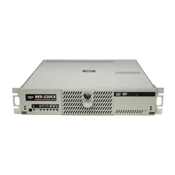
Preface This document, entitled RES-22DCX Installation Guide, provides instructions on how to install, configure, power up, boot, and perform diagnostics on the Themis Rugged Enterprise Server RES-22DCX (see photo below), which is based on two dual-core 64-bit Intel® Xeon CPUs. These instructions are intended for an experi- enced system administrator with a knowledge of both networking and high-speed server systems. - Page 26 RES-22DCX Installation Manual The 2RU-high (3.5”) RES-22DCX has been designed to fit into a standard 19” rack and is provided with rack-mount brackets without handles. Optional rack-mount brackets with handles and optional rack-mount slides are also available. The RES- 22DCX is rugged enough to withstand extreme shock (up to 25G), temperature (up to 50°C), and EMI such as that associated with such demanding markets as the mili-...
- Page 27 To reduce the risk of elec- trical shock and danger, follow the instructions accompanying this symbol. Sidebar: A “sidebar” adds detail to the section within which it is placed, but is not absolutely vital to the description or procedure of the section. Themis Computer...
- Page 28 RES-22DCX Installation Manual xxvi Themis Computer...
-
Page 29: Overview And Specifications
1RES-22DCX Overview and Specifications Overview The RES-22DCX (see Figure 1-1 and Figure 1-2, page 1-2) is a rack-mounted sys- tem designed specifically for above-average shock and vibe environments. The RES-22DCX supports single or dual Intel® 771-pin LGA Xeon 64-bit dual-core processors (each up to 2.33 GHz with a 1333-MHz system bus), and contains a com-... -
Page 30: Figure 1-2 Res-22Dcx System Block Diagram
PCI Riser Card The PCI Riser Card is installed into Slot 6 with connecting cables installed into Slot 2 and Slot 3. Slot 1, Slot 4, Slot 5, and the SIMLP Slot 7 are not used in the RES-22DCX. Slot 2 3.3V... -
Page 31: Figure 1-3 External Features Of The Res-22Dcx (Front And Rear)
Overview and Specifications Overview The RES-22DCX is designed within a 2RU-high (3.5”) form-factor 20” (50.8 cm) deep and 17” (43.2 cm) wide (which, with mounting brackets, fits a 19”-wide rack)— see Figure 1-3. Usable I/O expansion through three PCI slots mounted on a PCI Riser Card inserted into Slot 6 includes one PCI-Express (x16) slot and two 64-bit, 100/133 MHz PCI-X slots. -
Page 32: Table 1-1 Major Features Of The Res-22Dcx
NIC, etc.), two AC power supplies with latch locks and power-cord sockets, and all I/O connectors (Figure 1-5). Major features of the RES-22DCX are described in Table 1-1. Major internal com- ponents can be seen in the open top view (cover removed) of Figure 1-4 on page 1-6. - Page 33 USB headers are brought out to the rear of the chassis above the I/O Panel (see Figure 1-3, page 1-3, and Figure 1-5, page 1-10). Those who wish to customize USB ports should contact a local Themis sales office or info@themis.com. Themis Computer...
-
Page 34: Figure 1-4 Major Components Of The Res-22Dcx (Open Top View)
1 PCI-Express card • 2 PCI-X cards (64-bit) See Chapter 2 for more details. Front CD/DVD SCSI/SATA-II Disk-Drive (2) Dual 60-mm Fan Assembly Combo-Drive Housing (Two required) Housing Figure 1-4. Major Components of the RES-22DCX (Open Top View) Themis Computer... -
Page 35: Special Features
1.1.1.3 Fan Status Monitor The RES-22DCX has ten cooling fans—two 60-mm fans within each fan assembly at the front of the system, one on each CPU, and two within each power supply. The PC health-monitor utility can be used to check the RPM status of cooling fans. The onboard CPU and chassis fans are controlled by Thermal Management via BIOS. -
Page 36: Cpu Overheat Led And Control
Overheat warning LED. 1.1.1.7 IPMI Module Support The RES-22DCX motherboard contains a special SIM Low Profile IPMI 2.0 slot (see Figure 1-4) to install an optional Intelligent Platform Management Interface (IPMI) module. This invaluable health-monitoring tool provides full SNMP (includ- ing SNMP trap), some power cycle functions (reboot and graceful shutdown), and the ability to control other servers. -
Page 37: Suspend-State Indicator
ATX 2.01 (or higher)-compliant power supply only. If enabled in the system setup, the RES-22DCX power button on the front of the unit functions as a suspend button to make the system enter a SoftOff state. The monitor is suspended, and the hard drive will spin down. -
Page 38: System Leds And I/O Connectors
1.1.3 System LEDs and I/O Connectors All RES-22DCX system LEDs are located on the front panel (see Figure 1-5A); all I/O connectors are located on the rear panel (see Figure 1-5B). LEDs are described in Table 1-2 on page 1-11; connectors are described in Table 1-3, page 1-12. -
Page 39: Table 1-2 System Leds
The color of the left LED (when facing the port) indicates the LAN connection speed: - Off = 10 MHz LAN1 and LAN2 - Green = 100 MHz - Amber = 1 GHz The right LED, when lit, indicates LAN activity. a—NIC = Network Interface Controller. 1-11 Themis Computer... -
Page 40: Table 1-3 I/O Connectors
RES-22DCX Installation Manual Table 1-3. I/O Connectors Connector Description PS/2 Mouse 6-pin mini-DIN (female) connector to attach a PS/2 mouse device. PS/2 Keyboard 6-pin mini-DIN (female) connector to attach a PS/2 keyboard device. Four 4-pin USB connectors to attach serial devices to USB port 0 USB0 to USB3 through port 3. -
Page 41: Chipset Overview
Each of these channels can support up to four Dual Ranked FB-DIMM DDR2 DIMMs. FB-DIMM memory channels are organized in to two branches for support of RAID 1 (mirroring). The RES-22DCX MCH chipset connects up to 8 fully-buff- ered DIMM modules, providing a total of 32.0 GB/s for DDR2 667/533 memory. -
Page 42: The Intel 6321 Esb I/O Controller Hub (Ich)
RES-22DCX Installation Manual 1.2.2 The Intel 6321 ESB I/O Controller Hub (ICH) The Intel 6321 ESB I/O Controller Hub integrates an Ultra ATA 100 controller, six Serial ATA host controller ports, one EHCI host controller, and four UHCI host con- trollers supporting eight external USB 2.0 ports, LPC interface controller, flash... - Page 43 Port (BPP), Enhanced Parallel Port (EPP) or Extended Capabilities Port (ECP). Advanced Configuration and Power Interface (ACPI)-compliant functions support legacy and ACPI power management through an SMI or SCI function pin. An auto- power-management feature reduces power consumption. 1-15 Themis Computer...
-
Page 44: Specifications
RES-22DCX Installation Manual Specifications 1.3.1 General Table 1-4 lists general specifications for the RES-22DCX. Table 1-4. RES-22DCX General Specifications Parameter Description Dimensions 3.5” (2RU) high 17” (43.2 cm) wide (19” rack-mountable) 20” (50.8 cm) deep Weight Under 37 pounds (16.8 kg), includes 3 full-length (up to 12.25”) -
Page 45: Electrical
+3.3V, +5V, +5V sb , +12V, and -12V rails. 1.3.3 Environmental 1.3.3.1 Shock The RES-22DCX is designed to survive an elevated shock environment. All struc- tural components are welded together, enabling the system to survive a maximum 3-axis shock load of 25G at 40-ms duration. 1-17... -
Page 46: Electrostatic Discharge
The RES-22DCX is designed to tolerate electrostatic pulses up to 15 kilovolts (KV) with no impact on system operation. 1.3.3.3 Noise Level Typical noise levels emitted by the RES-22DCX are outlined in Table 1-6. The chas- sis is installed with two 60-mm fans per fan assembly (two assemblies per system are required). -
Page 47: Packaging And Shipping
D. Two Power-cord Retainer Velcro Straps When you unpack the RES-22DCX, please verify that all of these items are included. If any of these items are missing or not as pictured, please call Themis Technical Support at 510-252-0870, or send an email to support@themis.com. -
Page 48: Rack-Mount Slides (Optional)
1.4.2 Rack-Mount Slides (Optional) Rack-Mount Slides can be mounted on each side of the RES-22DCX, for the pur- pose of sliding the unit in and out of a rack. Mounting slides are optional and can be ordered at the time of purchase. -
Page 49: Installation And Operation
To install or replace a SCSI hard-disk drive or power supply, skip the next section and proceed directly to page 2-6 or page 2-15, respectively. Replacement of mother- board components require removal of the chassis protective cover. 2.1.1 Remove Protective Top Cover To access a motherboard component, open the RES-22DCX as follows: Themis Computer... -
Page 50: Figure 2-1 Remove The Res-22Dcx Protective Access Cover
1. Loosen the two captive Phillips screws holding the protective top access cover to the rear of the RES-22DCX chassis (see A, Figure 2-1). 2. Both the front and sides of the cover have flat hooks or tabs underneath that fit under slots on the chassis top edges (see B, Figure 2-1). -
Page 51: Memory Modules
(page 2-17). 2.1.2 Memory Modules The RES-22DCX supports up to eight registered ECC DDR2 Fully-buffered DIMM (FBD) Memory Modules (see Table 2-1), up to a total memory capacity of 32 GB (see Figure 2-2 on page 2-4). Table 2-1. -
Page 52: Installation
RES-22DCX Installation Manual 2.1.2.1 Installation The following procedure explains how to install the DDR2 FBD Memory Modules. 1. Loosen the four captive screws securing the memory retainer bracket and remove the bracket (see A, Figure 2-2). 2. Determine the location of the slot into which the Memory Module will be installed (see B, Figure 2-2). - Page 53 Note: Make sure the memory module has the proper orientation by align- ing the alignment notch at the bottom edge with its counterpart ridge at the bottom of the slot. Themis Computer...
-
Page 54: Scsi/Sata Ii Hard-Disk Drive
For SATA II drives, the upper left-hand removable disk drive (SATA II ID0) is designated as the boot drive. The front bezel of the RES-22DCX must be unlocked and opened to access the SCSI/SATA II hard-disk drives. -
Page 55: Disk-Drive Removal
. . . and pull drive out with the latch handle Latch Lock Latch Handle Figure 2-5. RES-22DCX Hard-Disk Drive Removal 4. Carefully pull the latch handle (see C) until the drive has cleared the chassis. The drive will automatically disconnect from its backplane connector when pulled forward. Themis Computer... -
Page 56: Disk-Drive Installation
The handle will swing closed when it comes into contact with the RES-22DCX chassis. 4. When the drive is fully inserted into its slot, push the latch handle closed until the latch lock has snapped into the locked position. -
Page 57: Pci Cards
2.1.4 PCI Cards Since the RES-22DCX is only 2RU (3.5”) high, PCI cards must be installed horizontally through the PCI Riser Card (see Figure 2-6), which supports a total of three PCI cards: • Upper Slot: One PCI-X (64-bit, 100/133-MHz) card •... -
Page 58: Figure 2-8 Pci Card Retainers Are Installed To Hold Long Pci Cards
Figure 2-7. The RES-22DCX PCI Riser Card Note: When your RES-22DCX system is shipped, the PCI Riser Card and its two cable connectors will already be installed, along with PCI cards you have ordered. To accommodate a long PCI card in the upper PCI Riser Card slot, card retainers will be installed within the chassis (see Figure 2-8). -
Page 59: Installation
Installation Procedures 2.1.4.1 Installation Follow these steps to install a PCI card in the RES-22DCX system: 1. Make sure that the 2RU-high PCI Riser Card is firmly inserted into Slot 6 of the motherboard (see Figure 2-6), and that both cable connectors are installed in their respective slots (2 and 3). - Page 60 RES-22DCX Installation Manual 9. If you have no further internal installations to perform, close the RES-22DCX chassis by refastening the top cover removed in Step 1 on page 2-2. Loosen the Phillips screw holding the PCI-Card retainer bracket and remove the bracket and screw .
-
Page 61: Removable 60-Mm Fan Housing
3. Four twisted wires form the cabling system of each housing. Carefully remove the 4-wire cable from its connector on the motherboard, remembering where each cable was attached. 4. The 60-mm fan housing can now be removed from the RES-22DCX chassis. Front 60-mm-Fan Housing Rear 60-mm Fan Housing... -
Page 62: Installing A 60-Mm Fan Housing
RES-22DCX Installation Manual 2.1.5.2 Installing a 60-mm Fan Housing Perform the following steps to install a 60-mm Fan Housing: 1. Insert the replacement 60-mm fan housing into the slot formerly occupied by the removed housing, aligning the key at each end of the new housing with the alignment slot (see Figure 2-11) in the fan-mounting bracket. -
Page 63: Power Supply
Push right to release power supply Extraction Handle Locking Lever Captive Power Supply Screw (1 of 2) Handle Retainer Captive Screw Power-Cord Bracket Figure 2-12. The RES-22DCX Power Supply Locking Mechanism 2-15 Themis Computer... -
Page 64: Installing A Power Supply
RES-22DCX Installation Manual 2.1.6.2 Installing a Power Supply Perform the following steps to install a power supply: 1. Insert the replacement power supply into an empty slot with the extraction handle facing to the right (see Figure 2-12). 2. Push the power supply carefully into its slot until it is firmly seated (a click will be heard when the locking lever is securely fastened to the chassis). -
Page 65: Lithium Battery
To release, squeeze the battery latch together ..and remove the battery from its socket Figure 2-13. The RES-22DCX Lithium Battery and Socket 2.1.7.2 Installing a Lithium Battery Perform the following steps to insert a new lithium battery: 1. -
Page 66: Rack Mounts
To learn how to install rack-mount slides, refer to Appendix B, “Rack-Mount Slide Installation”. Caution: Any screws used to mount a slide to a RES-22DCX chassis must not ex- ceed a length of 3/8” to prevent excessive penetration of the chassis. -
Page 67: Operation
2.3.1 Plugging in and Securing the AC Power Cords Before powering on the RES-22DCX, plug in and secure the AC power cords as follows: 1. If not already installed, secure the power-cord retainer bracket (see A, Figure 2-16 on page 2-20) to the rear corner of the chassis with the two cap- tive screws. -
Page 68: Figure 2-16 Secure All Power Cords With Bracket And Velcro Strap
RES-22DCX Installation Manual Power-cord Bracket Velcro Stap Figure 2-16. Secure all Power Cords with Bracket and Velcro Strap 2-20 Themis Computer... -
Page 69: Turning The System On
7. Using the bottom 4 slots on the power-cord bracket, repeat steps 3 through 6 to secure the lower AC power cord. Figure 2-17 shows the two power cords secured in place on the rear of the RES-22DCX. Figure 2-17. -
Page 70: Getting Started
1. To turn the RES-22DCX power off, press and hold the system power on/off button (see Figure 2-18, page 2-21) for at least four (4) seconds. This will shut down the system and turn off the POWER LED. -
Page 71: Appendix A. Connector Pinouts
This appendix provides connector pinouts for all standard user I/O interfaces on the RES-22DCX. PS/2 Keyboard and Mouse The RES-22DCX provides a 6-pin female mini-DIN connector for the PS/2 key- board, and another for the PS/2 mouse. Signals for both connectors are defined in Table A-1. -
Page 72: Usb Ports
I/O panel. Two additional USB ports can be accessed directly from the system motherboard. [Those who wish to customize USB ports should contact a local Themis sales office or info@themis.com.]. Pinouts are listed in Table A-2. -
Page 73: Serial Ports
Connector Pinouts Serial Ports Serial Ports The RES-22DCX supports two male DB9 serial port connectors on the rear I/O panel (see Figure A-2)—TTYA (COM1) and an optional TTYB (COM2). COM1 and COM2 pinouts are listed in Table A-3, page A-3. -
Page 74: Parallel Port
RES-22DCX Installation Manual Parallel Port The RES-22DCX supports a single female DB25 parallel port connector (see Figure A-3). Pinouts are listed in Table A-4. Figure A-3. DB25 Parallel Connector Table A-4. Parallel Port Connector Pinout Signal Description PAR_DS_L_CONN Data Strobe Low 2 to 9 PP_DAT[0..7]_CONN... -
Page 75: Gigabit Ethernet Lan Port
Connector Pinouts Gigabit Ethernet LAN Port Gigabit Ethernet LAN Port The RES-22DCX supports two RJ45 Gigabit Ethernet LAN port connectors—LAN1 and LAN2 (see Figure A-4). Pinouts are listed in Table A-5. Figure A-4. Gigabit Ethernet Connector, Type RJ45 Table A-5. - Page 76 RES-22DCX Installation Manual Themis Computer...
-
Page 77: Appendix B. Rack-Mount Slide Installation
An optional set of two rack-mount slides (left side and right side) is available for all RES-22 systems, and should be ordered at the time of purchase. The RES-22DCX chassis contains six threaded screw holes on each side to accommodate #8-32 size screws (included with the rack-mount slide kit);... - Page 78 Push the system into the rack until the mounting brackets on the front of the chassis are flush with the front of the rack. 6. Secure the RES-22DCX system to the 19” rack with two bolts on each side. Themis Computer...
- Page 79 (included in slide kit) Attach both inside slide sections to the left and right sides of the RES-22DCX chassis with #8-32 screws (included in slide kit) Figure B-1. RES-22DCX Rack-Mount Slide Installation Themis Computer...
- Page 80 RES-22DCX Installation ManualBB Themis Computer...
-
Page 81: Appendix C. Bios Setup Utility
Appendix BIOS Setup Utility Introduction This chapter describes the Phoenix BIOS™ Setup utility for the RES-22DCX. The Phoenix ROM BIOS is stored in a flash chip and can be easily upgraded using a floppy-disk-based program. Note: Due to periodic changes to the BIOS, some settings may have been added or Deleted and might not yet be recorded in this manual. -
Page 82: How To Change The Configuration Data
RES-22DCX Installation Manual C.1.2 How To Change the Configuration Data The CMOS information that determines the system parameters may be changed by entering the BIOS Setup utility. This Setup utility can be accessed by pressing the <Delete> key at the appropriate time during system boot. (See following Section.) C.1.3... -
Page 83: Main Bios Setup
With the item highlighted, press the <Enter> key to access the submenu. Press the <Esc> key to exit the CMOS Setup Menu. The next section describes in detail how to navigate through the menus. Figure C-1. The Main BIOS Setup Menu Themis Computer... -
Page 84: Main Setup Features
RES-22DCX Installation Manual C.3.1 Main Setup Features C.3.1.1 System Time To set the system date and time, key in the correct information in the appropriate fields. Then press the <Enter> key to save the data. C.3.1.2 System Date Using the arrow keys, highlight the month, day, and year fields, and enter the correct data. -
Page 85: Figure C-2 The Main Bios Setup Submenu
LBA Format The following items will be displayed by the BIOS: Total Sectors: This item displays the number of total sectors available in the LBA Format. Maximum Capacity: This item displays the maximum capacity in the LBA For- mat. Themis Computer... -
Page 86: Multi-Sector Transfer
RES-22DCX Installation Manual C.3.1.6 Multi-Sector Transfer This item allows the user to specify the number of sectors per block to be used in multi-sector transfer. The options are Disabled, 4 Sectors, 8 Sectors, and 16 Sectors. C.3.1.7 LBA Mode Control This item determines whether the Phoenix BIOS will access the IDE Channel 0 Mas- ter Device via the LBA mode. -
Page 87: Serial Ata (Sata) Raid Enable
Disabled. C.3.1.18System Memory This display informs you how much system memory is recognized as being present in the system. C.3.1.19Extended Memory This display informs you how much extended memory is recognized as being present in the system. Themis Computer... -
Page 88: Advanced Setup
RES-22DCX Installation Manual Advanced Setup Choose Advanced from the Phoenix BIOS Setup Utility main menu with the arrow keys. You should see the display shown in Figure C-3. The items with a triangle beside them have submenus that can be accessed by highlighting the item and press- ing <Enter>. -
Page 89: Quiet Boot
If enabled, this option will automatically reset the system if the system is not active for more than 5 minutes. The options are Enabled and Disabled. C.4.1.9 Summary Screen This setting allows you to Enable or Disable the summary screen which displays the system configuration during bootup. Themis Computer... -
Page 90: Memory Cache
RES-22DCX Installation Manual C.4.2 Memory Cache C.4.2.1 Cache System BIOS Area This setting allows you to designate a reserve area in the system memory to be used as a System BIOS buffer to allow the BIOS write (cache) its data into this reserved memory area. -
Page 91: Cache Extended Memory
C.4.3.3 PCI Parity Error Forwarding The feature allows SERR and PERR errors detected in PCI slots to be sent (for- warded) to the BIOS DMI Event Log for the user to review. The options are Enabled and Disabled. C-11 Themis Computer... -
Page 92: Reset Configuration Data
RES-22DCX Installation Manual C.4.3.4 Reset Configuration Data If set to Yes, this setting clears the Extended System Configuration Data- (ESCD) area. The options are Yes and No. C.4.3.5 Frequency for PCI-X#1, PCI-X#2-#3 This option allows the user to change the bus frequency for the devices installed in the slot indicated. -
Page 93: Advanced Chipset Control
Select enable to enable the sparing feature for Branch 0 of memory bus. The options are Enabled and Disabled. C.4.5.5 Branch 1 Rank Sparing Select enable to enable the sparing feature for Branch 1 of memory bus. The options are Enabled and Disabled. C-13 Themis Computer... -
Page 94: Enhanced X8 Detection
Note: A TOE device is a specialized, dedicated processor that is installed on an add-on card or a network card to handle some or all packet processing of this add- on card. For the RES-22DCX, the TOE device is built inside the ESB 2 South- Bridge chip. -
Page 95: Advanced Processor Options
C.4.6.7 C1 Enhanced Mode (Only when supported by the CPU) Set to Enabled to enable Enhanced Halt State to lower CPU voltage/frequency to prevent overheat. The options are Enabled and Disabled. [Please refer to the Intel website for detailed information.] C-15 Themis Computer... -
Page 96: No Execute Mode Memory Protection (Only When Supported By The Cpu And The Os
RES-22DCX Installation Manual C.4.6.8 No Execute Mode Memory Protection (Only when supported by the CPU and the OS) Set to Enabled to enable Execute Disable Bit and allow the processor to classify areas in memory where an application code can execute and where it cannot, and thus preventing a worm or a virus from inserting and creating a flood of codes to overwhelm the processor or damage the system during an attack. -
Page 97: Intel Eist Support (Only When Supported By The Cpu
(user defined), Disabled, Auto (BIOS controlled) and OS Controlled. C.4.7.6 Mode This setting allows you to set the type of device that will be connected to serial port B. The options are Normal and IR (for an infrared device). C-17 Themis Computer... -
Page 98: Base I/O Address
RES-22DCX Installation Manual C.4.7.7 Base I/O Address This setting allows you to select the base I/O address for serial port B. The options are 3F8, 2F8, 3E8 and 2E8. C.4.7.8 Interrupt This setting allows you to select the IRQ (interrupt request) for serial port B. The options are IRQ3 and IRQ4. -
Page 99: Dmi Event Logging
Access the submenu to make changes to the following settings. C.4.9.1 COM Port Address This item allows you to specify to redirect the console to Onboard COM A or Onboard COM B. This setting can also be Disabled. C-19 Themis Computer... -
Page 100: Baud Rate
RES-22DCX Installation Manual C.4.9.2 BAUD Rate This item allows you to select the BAUD rate for console redirection. The options are 300, 1200, 2400, 9600, 19.2K, 38.4K, 57.6K, and 115.2K. C.4.9.3 Console Type This item allows you to choose from the available options to select the console type for console redirection. - Page 101 (12V) at all the time. The Options are: 1. Disable 2. 3-pin (Server) 3. 3-pin (Workstation) 4. 4-pin (Server) 5. 4-pin (Workstation). C.4.10.3Voltage Monitoring The following items will be monitored and displayed: • P12V_VR0 • P12V_VR1 • FSB VTT • PXH Vcore C-21 Themis Computer...
-
Page 102: Cpu Temperature Threshold
RES-22DCX Installation Manual • ES2B Vcore • CPU1Vcore • CPU2Vcore • P3V3 C.4.11 Hardware Monitor Logic [Alternative 2] C.4.11.1 CPU Temperature Threshold This option allows the user to set a CPU temperature threshold that will activate the alarm system when the CPU temperature reaches this pre-set temperature threshold. -
Page 103: Voltage Monitoring
The hardcode default setting is 72 C.4.12.2Temperature Monitoring Highlight this and hit <Enter> to see monitor data for the following items: • PECI Agent 1 Temperature • PECI Agent 2 Temperature • PECI Agent 3 Temperature • PECI Agent 4 Temperature C-23 Themis Computer... - Page 104 RES-22DCX Installation Manual • System Temperature • Fan1-Fan8 Speeds—If the feature of Auto Fan Control is enabled, the BIOS will automatically display the status of the fans indicated in this item. C.4.12.3Fan Speed Control Modes This feature allows the user to decide how the system controls the speeds of the onboard fans.
-
Page 105: Ipmi (Only When An Ipmi Card Is Installed In The System
This item displays the current Firmware Version. C.4.13.3System Event Logging Select Enabled to enable IPMI Event Logging. When this function is set to Disabled, the system will continue to log events received via system interface. The options are Enabled and Disabled. C-25 Themis Computer... -
Page 106: Existing Event Log Number
RES-22DCX Installation Manual C.4.13.4Clear System Event Logging Enabling this function to force the BIOS to clear the system event logs during the next cold boot. The options are Enabled and Disabled. C.4.13.5Existing Event Log Number This item displays the number of the existing event log. -
Page 107: System Event Log/System Event Log (List Mode
• SEL Record Type • Time Stamp • Generator ID • SEL Message Revision • Sensor Type • Sensor Number • SEL Event Type • Event Description • SEL Event Data. Figure C-5. The System Event Log Submenu C-27 Themis Computer... -
Page 108: Realtime Sensor Data
RES-22DCX Installation Manual C.4.15 Realtime Sensor Data This feature display information from motherboard sensors, such as temperatures, fan speeds and voltages of various components. Figure C-6. The Realtime Sensor Data Submenu C-28 Themis Computer... -
Page 109: Security Settings
Set means a supervisor password has been entered for the system. C.5.2 User Password Is: This displays whether a user password has been entered for the system. Clear means C-29 Themis Computer... -
Page 110: Set Supervisor Password
RES-22DCX Installation Manual such a password has not been used and Set means a user password has been entered for the system. C.5.3 Set Supervisor Password When the item “Set Supervisor Password” is highlighted, hit the <Enter> key. When prompted, type the Supervisor's password in the dialogue box to set or to change supervisor's password, which allows access to the BIOS. -
Page 111: Boot Settings
<x> key to remove it from the candidate list and put it in the boot list. This item will then become a bootable device. See details on how to change the priority of boot order of devices in the “Item Specific Help” win- dow. C-31 Themis Computer... -
Page 112: Exit
RES-22DCX Installation Manual Exit Choose Exit from the Phoenix BIOS Setup Utility main menu with the arrow keys. You should see the following display. All Exit BIOS settings are described in this section. Figure C-9. The BIOS Setup Exit Submenu C.7.1... -
Page 113: Load Setup Defaults
Highlight this item and hit <Enter> to discard (cancel) any changes you made. You will remain in the Setup utility. C.7.5 Save Changes Highlight this item and hit <Enter> to save any changes you made. You will remain in the Setup utility. C-33 Themis Computer... -
Page 114: Bios Post Messages
RES-22DCX Installation Manual BIOS POST Messages During the Power-On Self-Test (POST), the BIOS will check for problems. If a problem is found, the BIOS will activate an alarm or display a message. The follow- ing is a list of such BIOS messages. - Page 115 Diskette drive B error Drive A: or B: is present but fails the BIOS POST diskette tests. Check to see that the drive is defined with the proper diskette type in Setup and that the diskette drive is attached correctly. C-35 Themis Computer...
- Page 116 RES-22DCX Installation Manual Incorrect Drive A type - run SETUP Type of floppy drive A: not correctly identified in Setup. Incorrect Drive B type - run SETUP Type of floppy drive B: not correctly identified in Setup. System cache error - Cache disabled RAM cache failed and BIOS disabled the cache.
- Page 117 Where nnnn is the amount of system RAM in kilobytes successfully tested. One or more I2O Block Storage Devices were excluded from the Setup Boot Menu There was not enough room in the IPL table to display all installed I2O block-stor- age devices. C-37 Themis Computer...
- Page 118 RES-22DCX Installation Manual Operating system not found Operating system cannot be located on either drive A: or drive C:. Enter Setup and see if fixed disk and drive A: are properly identified. Parity Check 1 nnnn Parity error found in the system bus. BIOS attempts to locate the address and display it on the screen.
-
Page 119: Appendix D. Red Hat Enterprise Linux Installation
2. Make sure the operating system selection under advanced menu is set to “Linux” or “other” for Linux installation. D.2.2 Installing from CD-ROM To install Red Hat Enterprise Linux from a CD-ROM, insert the Red Hat Enterprise Themis Computer... -
Page 120: Language Selection
RES-22DCX Installation Manual Linux CD into your CD-ROM drive and boot the system. The system will boot from CD-ROM and display the “Boot” prompt. Press [Enter], after which the following message appears: “Welcome to Red Hat Enterprise Linux” Note: The CD-ROM is required when booting the installation program, and again after subsequent CD-ROMs has been processed. -
Page 121: Keyboard Selection
On this screen (see Figure D-3 on page D-4), you can choose to perform automatic partitioning, or manual partitioning using Disk Druid. Automatic partitioning allows you to perform an installation without having to parti- tion your drive(s) yourself. If you do not feel comfortable with partitioning your sys- Themis Computer... -
Page 122: Figure D-3 Disk Partitioning
RES-22DCX Installation Manual tem, it is recommended that you do not choose to partition manually and instead let the installation program partition for you. To partition manually, choose the Disk Druid partitioning tool. Figure D-3. Disk Partitioning Note: If you receive an error after the Disk Partitioning Setup phase of the instal- lation saying something similar to: The partition table on device hda was unreadable. -
Page 123: Automatic Partitioning
Remove all partitions on this system. Select this option to remove all partitions on your hard drive(s) (this includes partitions created by other operating systems such as Windows VFAT or NTFS partitions). Note: If you select this option, all data on the selected hard drive(s) is removed by the installation program. Themis Computer... -
Page 124: Partitioning Your System
RES-22DCX Installation Manual Also, do not select this option if you have information that you want to keep on the hard drive(s) where you are installing Red Hat Enterprise Linux. Keep all partitions and use existing free space. Select this option to retain your current data and partitions, assuming you have enough free space available on your hard drive(s). -
Page 125: Adding Partitions
D—Red Hat Enterprise Linux Installation Installation Figure D-5. Disk Setup D.2.2.6 Adding Partitions To add a new partition, select the New button. The following dialog box appears: Figure D-6. Add Partition Themis Computer... - Page 126 RES-22DCX Installation Manual Mount Point: Enter the partition's mount point. For example, if this partition should be the root partition, enter /; enter /boot for the /boot partition, and so on. You can also use the pull-down menu to choose the correct mount point for your partition.
-
Page 127: Boot Loader Configuration
GRUB (Grand Unified Bootloader), which is installed by default, is a very powerful boot loader. GRUB can load a variety of free operating systems, as well as proprietary operating systems with chain-loading (the mechanism for loading unsupported operating sys- tems, such as DOS or Windows, by loading another boot loader). Themis Computer... -
Page 128: Advanced Boot Loader Configuration
RES-22DCX Installation Manual D.2.2.8 Advanced Boot Loader Configuration Now that you have chosen which boot loader to install, you can also determine where you want the boot loader to be installed. You may install the boot loader in one of two places: The master boot record (MBR). -
Page 129: Network Configuration
If you select Activate on boot, your network interface is started when you boot. If you do not have DHCP client access or you are unsure what to provide here, please contact your network administrator D-11 Themis Computer... -
Page 130: Figure D-10 Editing A Network Device
RES-22DCX Installation Manual Figure D-10. Editing a Network Device If you have a hostname (fully qualified domain name) for the network device, you can choose to have DHCP (Dynamic Host Configuration Protocol) automatically detect it or you can manually enter the hostname in the field provided. -
Page 131: Figure D-11 Firewall Configuration
A properly con- figured firewall can greatly increase the security of your system. Figure D-11. Firewall Configuration Next, you can decide whether to enable a firewall for your Red Hat Enterprise Linux system. D-13 Themis Computer... -
Page 132: Time Zone Configuration
RES-22DCX Installation Manual D.2.2.11 Time Zone Configuration Set your time zone by selecting the city closest to your computer's physical location. There are two ways for you to select your time zone: Using your mouse, click on the interactive map to select a specific city (represented by a yellow dot). -
Page 133: Set Root Password
[Enter]. Then, enter the root password and press [Enter]. The installation program prompts you to set a root password for your system. You cannot proceed to the next stage of the installation process without entering a root password D-15 Themis Computer... -
Page 134: Package Group Selection
RES-22DCX Installation Manual The root password must be at least six characters long; the password you type is not echoed to the screen. You must enter the password twice; if the two passwords do not match, the installation program asks you to enter them again. -
Page 135: Figure D-15 Package Group Selection
Red Hat Enterprise Linux. Once a package group has been selected, click on Details to view which packages are installed by default, and to add or remove optional packages from that group (see Figure D-16 on page D-18). D-17 Themis Computer... -
Page 136: Preparing To Install
RES-22DCX Installation Manual Figure D-16. Package Group Details D.2.2.14Preparing to Install A screen preparing you for the installation of Red Hat Enterprise Linux now appears. For your reference, a complete log of your installation can be found in /root/install. log once you reboot your system. -
Page 137: Installation Complete
After installing all the packages, you will get the following message: Congratulations! Your Red Hat Enterprise Linux installation is now complete! Finally, the installation program prompts you to prepare your system for reboot. Remember to remove any installation media and press Reboot to reboot the system. D-19 Themis Computer... - Page 138 RES-22DCX Installation Manual D-20 Themis Computer...
-
Page 139: Index
BIOS Setup Boot Submenu C-31 Legacy USB Support C-14 BIOS Setup Exit Submenu C-32 Memory Branch Mode C-13 BIOS Setup Security Submenu C-29 Route Port 80h Cycles C-14 BIOS Setup utility C-1, C-2 SERR Signal Condition C-13 Index-1 Themis Computer... - Page 140 RES-22DCX Installation Manual Boot Features removal 2-7 ACPI Mode C-9 Disk Partitioning D-4 ACPI Sleep Mode C-9 Disk Setup D-7 Power Button Behavior C-9 disk-drive adapter functions, super I/O 1-14 Power Loss Control C-9 DMI Event Logging Quick Boot Mode C-8...
- Page 141 Serial Ports 1-12 L2 cache 1-4 USB Serial Ports 1-12 LAN port A-5 I/O Controller Hub (ICH) 1-13, 1-14 Language Selection D-2 I/O Device Configuration latch locks 1-4 Base I/O Address C-17, C-18 LEDs DMA Channel C-18 Index-3 Themis Computer...
- Page 142 Noise Level 1-18 Notes xxv Main BIOS Setup Menu C-3 Main BIOS Setup Submenu C-5 Main Setup Features Opening the RES-22DCX Front Bezel 2-6 32 Bit I/O C-6 Operating temperature 1-5 BIOS Date C-4 Output Voltage 1-17 CHS Format C-5...
- Page 143 Select Disk Partitioning Setup D-3 LED 2-22 Set Root Password D-15 power cords 2-21 Time Zone Configuration D-14 power supply 1-5, 2-1, 2-21 RES-22DCX 1-1 installation 2-16 reset switch 1-4 locking mechanism 2-15 retainer bracket, power cord 2-19 removal 2-15...
- Page 144 RES-22DCX Installation Manual Supervisor Password Is Super I/O 1-14 C-29 SuperMicro web site C-1 serial ports 1-5, A-3 Suspend-State Indicator 1-9 Set Root Password D-15 SVGA connector 2-22 Setup program C-2 system bus speed 1-4 shock xxiv, 1-17 System Event Log (SEL) C-27...
- Page 145 — Xeon processors 1-1, 1-4, 1-13 Index-7 Themis Computer...
- Page 146 RES-22DCX Installation Manual Index-8 Themis Computer...
- Page 147 Place Stamp Here Themis Computer 47200 Bayside Parkway Fremont, CA 94538 Attn: Publications Department Fold here; tape at top to seal...
-
Page 148: Reader Comment Card
Reader Comment Card We welcome your comments and suggestions to help improve the RES-22DCX Installation Manual. Please take time to let us know what you think about this manual. • Information provided in the manual was complete. Agree___ Disagree___ Not Applicable___ •...
Need help?
Do you have a question about the RES-22DCX and is the answer not in the manual?
Questions and answers