
Related Manuals for Themis RES-11XR3


Summary of Contents for Themis RES-11XR3
- Page 1 User M anual User M anual I nstallation I nstallation M anual M anual 1RU 19” Rack-Mount Rugged Enterprise Server with X8STi Motherboard Configuration /One Quad-Core 5500 or Quad/Six-Core 5600 Xeon CPU...
-
Page 3: Res-11Xr3 Installation Manual
RES-11XR3 Installation Manual* Version 1.0— July 2010 * SuperMicro Motherboards X8STi, X8STi-F, X8STi-LN4, X8STi-3F Themis Computer—Americas and Pacific Rim Themis Computer—Rest of World 47200 Bayside Parkway 5 Rue Irene Joliot-Curie Fremont, CA 94538 38320 Eybens, France Phone (510) 252-0870 Phone +33 476 14 77 80... -
Page 4: Safety Precautions
Themis Computer assumes no responsibility for inaccuracies. Themis Computer retains the right to make changes to this publication at any time without prior notice. Themis Computer does not assume any liability arising from the application or use of this publication or the product(s) described herein. - Page 5 RES-11XR3 Installation Manual Version Revision History Version 1.0 ....................July 2010 Themis Computer...
-
Page 6: Safety Instructions
In these cases, the device must be shut down and secured against unintentional operation. • Repairs may only be carried out by a person authorized by Themis Computer. • The device may only be opened for the installation and removal of extension... -
Page 7: Grounding Methods
RES-11XR3 Installation Manual and the lithium battery—all in accordance with the instructions given in this manual. • If extensions are made to the device, the legal stipulations and the device spec- ifications must be observed. • The device must be switched off when removing the top cover; for example, before installing extension (PCI) cards. - Page 8 RES-11XR3 Installation Manual 2. Use anti-static mats, heel straps, or air ionizers to give added protection. 3. Handle electrostatic-sensitive components, boards, and assemblies by the case or the PCB edge. 4. Avoid contact with pins, leads, or circuitry. 5. Turn off power and input signals before inserting and removing connectors or test equipment.
-
Page 9: Table Of Contents
1.5.1 Overview of the Winbond WPCM450 Controller ........1-10 1.6 System LEDs and I/O Connectors ............... 1-11 1.7 Specifications ....................... 1-14 1.7.1 General ..................... 1-14 1.7.2 Electrical ....................1-15 1.7.2.1 System Power ................1-15 1.7.2.2 Output Voltage ................1-15 1.7.3 Environmental ..................1-16 Themis Computer... - Page 10 2.1.4.1 Removing the Lithium Battery ..........2-13 2.1.4.2 Installing a Lithium Battery ............2-14 2.1.5 SAS/SATA Storage Drive ............... 2-14 2.1.5.1 Opening the RES-11XR3 Front Doors ........2-14 2.1.5.2 Disk-Drive Removal ..............2-15 2.1.5.3 Disk-Drive Installation ............. 2-17 2.1.6 Hot-Swappable 38-mm Fan ..............2-17 2.1.6.1 Removing and Installing a 38-mm Fan ........
- Page 11 3.2.2.7 Intel® AES-NI (When supported by the CPU) ......3-8 3.2.2.8 Simultaneous Multi-Threading (Available when supported by the CPU) ........3-8 3.2.2.9 Active Processor Cores ............... 3-8 3.2.2.10 Intel® EIST Technology ............. 3-8 3.2.2.11 Intel® TurboMode Technology ..........3-9 Themis Computer...
- Page 12 RES-11XR3 Installation Manual 3.2.2.12 Intel® Turbo Boost (Available if Intel® EIST Technology is Enabled ) ....3-9 3.2.2.13 C1E Support ................3-9 3.2.2.14 Intel® C-STATE Tech ..............3-9 3.2.2.15 C-State package limit setting ............3-9 3.2.2.16 C1 Auto Demotion ..............3-9 3.2.2.17 C3 Auto Demotion ..............
- Page 13 3.3.9.4 Fan Speed Control Modes ............3-23 3.3.9.5 Voltage Monitoring ..............3-24 3.3.10 ACPI Configuration ................. 3-24 3.3.10.1 High Performance Event Timer ..........3-24 3.3.10.2 ACPI Aware O/S ..............3-24 3.3.10.3 AMI OEMB Table ..............3-24 3.3.10.4 ACPI APIC Support ..............3-24 Themis Computer...
- Page 14 RES-11XR3 Installation Manual 3.3.10.5 APIC ACPI SCI IRQ ..............3-25 3.3.10.6 Headless Mode ................3-25 3.3.10.7 ACPI Version Features ............. 3-25 3.3.11 IPMI Configuration (X8STi-F/X8STi-3F Only) ........3-25 3.3.11.1 IPMI Firmware Version ............3-25 3.3.11.2 Status of BMC Working ............3-25 3.3.12 View BMC System Event Log ..............
- Page 15 D.2 Remote Only Configuration .................. D-2 D.3 Ordering the Remote On/Off Switch ..............D-2 Appendix E. Re-Packing Instructions ................E-1 E.1 Re-Packaging for Shipment ...................E-1 E.2 Packing Components .....................E-1 E.3 Instructions for Re-Packing ...................E-2 Index ........................ Index-1 Reader Comment Card xiii Themis Computer...
- Page 16 RES-11XR3 Installation Manual Themis Computer...
- Page 17 External Features of the RES-11XR3 .............. 1-3 Figure 1-3 X8STi series Motherboard Block Diagram ............. 1-4 Figure 1-4 Open Top View of the RES-11XR3—Air Flow Diverter Removed ....1-6 Figure 1-5 RES-11XR3 System LEDs and I/O Connectors..........1-11 Figure 2-1 Remove the RES-11XR3 Protective Access Cover.........
- Page 18 RES-11XR3 Installation Manual Figure 2-21 System Power Button and LED on the RES-11XR3 Front ......2-23 Figure 3-1 Main BIOS Setup Screen ................. 3-3 Figure 3-2 Advanced Settings ................... 3-5 Figure 3-3 Security Settings .................... 3-28 Figure 3-4 Boot Settings....................3-30 Figure 3-5 Exit Options ....................
- Page 19 Approximate Weights of the RES Series............1-19 Table 2-1 RES-11XR3 Memory Capacity ..............2-3 Table 2-2 RES-11XR3 Optimal Memory Population (CPU1 Installed)......2-3 Table 2-3 PCI Riser Cards for 1RU and 2RU XR3 systems........... 2-8 Table A-1 PS/2 Keyboard/Mouse Pinouts and Signal Definitions ......... A-1 Table A-2 USB Connector Signal Definitions..............
- Page 20 RES-11XR3 Installation Manual Themis Computer...
-
Page 21: Preface
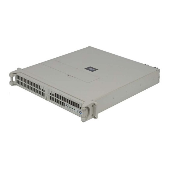
Preface This document, entitled RES-11XR3 Installation Manual, provides instructions on how to install, configure, power up, boot, and perform diagnostics on the Themis Rugged Enterprise Server RES-11XR3 (see photo), based on a single Intel Xeon Quad/Dual-Core 5500 or Quad/Six-Core 5600 CPU in an LGA1366 socket. - Page 22 RES-11XR3 Installation Manual Table 1. RES-x2XR3 20” Chassis Manual Matrix (AC and DC Power Supplies) RES-32XR3 RES-22XR3 RES-22XR3 RES-12XR3 Category Motherboard Manual Manual Manual Manual kets Part Number Part Number Part Number Part Number X8DTH-iF Configuration 1 116790-024 1176789-024 X8DTH-6F...
- Page 23 T = Graphics chip; no sound chip w: Not applicable x: i = SATA only 3 = SAS 1.0 6 = SAS 2.0 y: LN4 = Extra gigabit Ethernet controller for two extra ports z: F = IPMI blank = No IPMI Themis Computer...
- Page 24 F = IPMI blank = No IPMI The 1RU-high (1.75”) RES-11XR3 has been designed to fit into a standard 19” rack and is provided with rack-mount brackets with handles. Optional rack-mount slides are also available. The RES-11XR3 is rugged enough to withstand extreme shock (up to 35G), temperature, and EMI associated with such demanding markets as the military, aerospace, and telecommunications industries.
-
Page 25: Website Information
This manual is intended for an experienced system administrator with a knowledge of both networking and high-speed server systems. Website Information Themis Computer corporate and product information may be accessed on the World Wide Web by browsing the website http://www.themis.com. Your Comments are Welcome We are interested in improving our documentation and welcome your comments and suggestions. - Page 26 RES-11XR3 Installation Manual Caution: A caution describes a procedure or action that may result in damage to the equipment. This may involve—but is not restricted to—heavy equipment or sharp objects. To reduce the risk, follow the instructions accompanying this sym- bol.
-
Page 27: Overview And Specifications
The RES-11XR3 is a rack-mounted system for above-average shock and vibration environments (see Figure 1-1 below and Figure 1-2 on page 1-3; a block diagram is ® given in Figure 1-3, page 1-4). The RES-11XR3 supports a single Intel 1366-pin LGA Xeon 64-bit processor (up to 2.33 GHz with a 1333-MHz system bus), and... -
Page 28: Table 1-1 Res-11Xr3 Motherboard Options
RES-11XR3 Installation Manual Table 1-1. RES-11XR3 Motherboard Options PCI-e and PCI Slots Mother- Memory IPMI SATA Graphics Audio PCI-e PCI-e board Slots 2.0 x16 X8STi — X8STi-F — X8STi-LN4 — X8STi-3F — a—SuperMicro Computer, Inc. b—32-bit slot Table 1-2. Differences Between Main Features of the X8STi motherboards... -
Page 29: Figure 1-2 External Features Of The Res-11Xr3
The RES-11XR3 is designed within a 1RU-high (1.75”) form-factor, 17” (43.2 cm) deep and 17.07” (43.4 cm) wide, (which, with mounting brackets, fits a 19”-wide rack; see ). Major features of the RES-11XR3 are described in Table 1-3, page 1-5. CD-RW/DVD-ROM... -
Page 30: Figure 1-3 X8Sti Series Motherboard Block Diagram
COM 2 Figure 1-3. X8STi series Motherboard Block Diagram The RES-11XR3 front panel houses three removable storage drive bays that support SAS/SATA drives. Storage drive requirements should be ordered at the time of pur- chase. Also included on the front panel is a combination CD-RW/DVD-ROM drive, an ON/OFF power button, and system LEDs (see Figure 1-4 on page 1-12). -
Page 31: Table 1-3 Major Features Of Res-11Xr3
Overview and Specifications Overview Table 1-3. Major Features of RES-11XR3 Feature Details One Quad-Core/Dual-Core Intel® 5500 Series or Quad/Six-Core 5600 Series Processor (CPU) Xeon Processor with QPI (QuickPath Interconnect) links up to a 51.2 GT/s data-transfer rate (6.4 GT/s per direction) Intel®... -
Page 32: Figure 1-4 Open Top View Of The Res-11Xr3-Air Flow Diverter Removed
PCI-e x 16 (Riser Card Slot) PCI Card Slot 6 DIMM Memory Module Slots 38-mm Fan (Five Total) Disk Drive (Total of 3) Front CD/DVD Combo-Drive Housing Figure 1-4. Open Top View of the RES-11XR3—Air Flow Diverter Removed Themis Computer... -
Page 33: Chipset Overview
BIOS provides a setting for you to determine how the system will respond when AC power is lost and then restored to the system. You can choose for the system to remain powered off (in which case you must hit the power switch to turn it back on) Themis Computer... -
Page 34: Onboard Voltage Monitoring
SD III. 1.3.3 Fan Status Monitor with Software The RES-11XR3 has five 38-mm cooling fans and one within each power supply. PC Health Monitoring can check the RPM status of the cooling fans via SuperO Doctor III. -
Page 35: Slow Blinking Led For Suspend-State Indicator
In addition, an onboard LAN controller can also support WOL without any connection to the WOL header. The 3-pin WOL header is to be used with a LAN add-on card only. Note: Wake-On-LAN requires an ATX 2.01 (or above) compliant power supply. Themis Computer... -
Page 36: Super I/O
RES-11XR3 Installation Manual Super I/O The disk drive adapter functions of the Super I/O chip include a floppy disk drive controller that is compatible with industry standard 82077/765, a data separator, write pre-compensation circuitry, decode logic, data rate selection, a clock genera- tor, drive interface control logic and interrupt and DMA logic. -
Page 37: System Leds And I/O Connectors
VGA (Blue) LAN 1 LAN 2 USB Port 1 (top) Gigabit Ethernet USB Port 0 (bottom) Figure 1-5. RES-11XR3 System LEDs and I/O Connectors All RES-11XR3 system LEDs are located on the front panel (see A, Figure 1-5, 1-11 Themis Computer... -
Page 38: Table 1-4 System Leds
RES-11XR3 Installation Manual page 1-11); all I/O connectors are located on the rear panel (see B, Figure 1-5). LEDs are described in Table 1-4; I/O connectors are described in Table 1-5, page 1- Table 1-4. System LEDs Symbol Description Power Indicates that the system is turned on. -
Page 39: Table 1-5 Rear-Panel I/O Connectors
LED is at the front of the motherboard). Pressing the UID again turns off both LED indicators. The UID indicators provide an easy identifi- cation of a system unit that may be in need of service. Note: The UID can also be triggered via IPMI. 1-13 Themis Computer... -
Page 40: Specifications
RES-11XR3 Installation Manual Specifications 1.7.1 General Table 1-6 lists general specifications for the RES-11XR3. Table 1-6. RES-11XR3 General Specifications Parameter Description Dimensions 1.75” (1RU) high 17.07” (43.4 cm) wide (19” rack-mountable) 17” (43.2 cm) deep Approximately 16.5 pounds (7.5 kg); includes 2 full-length Weight (up to 12.25”) PCI cards, 1 CD-RW/DVD-ROM drive, 1... -
Page 41: Electrical
= Not Applicable. 1.7.2.1 System Power The RES-11XR3 operates with two N+1 redundant power supplies of 750-watts capacity each that auto-range single-phase AC input from 100 to 265 Vac (47 to 63 Hertz) sources. Filtered and fused (internal) AC is supplied to each power supply from a rear-mounted power connection. -
Page 42: Environmental
3-axis shock load of 35G at 25-ms duration. 1.7.3.2 Electrostatic Discharge The RES-11XR3 is designed to tolerate electrostatic pulses up to 15 kilovolts (KV) with no impact on system operation. 1.7.3.3 Noise The RES-11XR3 conforms to the 54-db noise specifications.. -
Page 43: Accessory Kit
B. Two AC Power Cords C. Two Front-Bezel Barrel Keys When you unpack the RES-11XR3, please verify that all of these items are included. If any of these items are missing or not as pictured, please call Themis Technical Support at 510-252-0870, or send an email to support@themis.com. -
Page 44: Table 1-8 Approximate Weights Of The Res Series
RES-11XR3 Installation Manual Table 1-8. Approximate Weights of the RES Series Weight Model Depth Description (Approximate) Sockets RES-12XR3 19.5 lbs (8.9 kg) 20” Includes: All CPU sockets filled 6 DIMMs RES-12XR3-S 17 lbs (7.7 kg) 17” 2 storage drives 2 PCI cards... -
Page 45: Installation And Operation
2-14, page 2-17, or page 2-20, respectively. Replacement of motherboard components requires removal of the protective cover. 2.1.1 Remove Protective Top Cover To access a motherboard component, open the RES-11XR3 as follows: Themis Computer... -
Page 46: Figure 2-1 Remove The Res-11Xr3 Protective Access Cover
1. Loosen the two captive Phillips screws holding the protective top access cover to the rear of the RES-11XR3 chassis (see A, Figure 2-1). 2. Both the front and sides of the cover have flat hooks or tabs underneath that fit under slots on the chassis top edges (see B, Figure 2-1). -
Page 47: Memory Modules
Installation and Operation Installation Procedures 2.1.2 Memory Modules The RES-11XR3 supports memory according to Table 2-1. Table 2-1. RES-11XR3 Memory Capacity Memory Parameters DDR3 Motherboard Number Pins per Capacity Registered Speed (MHz) of DIMMS DIMM X8STi series 24 GB 1333/1066/800 Caution: Exercise extreme caution when installing or removing Memory Modules to prevent any possible damage. -
Page 48: Installation
1. Loosen and remove the five (5) screws securing the air-flow deflector (see Figure 2-2). Figure 2-2. Remove RES-11XR3 Air-Flow Deflector 2. After the air-flow deflector is removed, the memory modules will be exposed (see Figure 1-4 on page 1-6). -
Page 49: Figure 2-3 Memory Module Slot Locations
(see Figure 2-4 on page 2-6), then pulling the old module directly up from the slot until it is free of the connector (see Figure 2-4). Themis Computer... - Page 50 RES-11XR3 Installation Manual Press latch downward & outward at each end Figure 2-4. Memory Module Removal 4. Before inserting a new memory module into the vacant slot, make sure that the two latches are pulled outward away from the center of the slot.
-
Page 51: Pci Cards
Installation Procedures 2.1.3 PCI Cards Since the RES-11XR3 is only 1RU (1.75”) high, PCI cards must be installed hori- zontally through PCI Riser Cards (see Figure 2-5). The riser card used in the RES- 11XR3 is installed in Slot 6 PCI-Express 2.0 x16 horizontally... -
Page 52: Table 2-3 Pci Riser Cards For 1Ru And 2Ru Xr3 Systems
RES-11XR3 Installation Manual 2RU systems is shown in Table 2-3, page 2-8. . Table 2-3. PCI Riser Cards for 1RU and 2RU XR3 systems Riser Card Output Slots Riser Card XR3 Box PCI-E x8 PCI-E x16 PCI-X RES-12XR3 RSC-R1UU-E16 RES-22XR3... -
Page 53: Installing Cards
1. Locate the slot on the riser card (see Figure 2-5 on page 2-7) within which a card will be installed and remove the Phillips screw holding the blank I/O faceplate corresponding to the slot (see Figure 2-8). Themis Computer... -
Page 54: Figure 2-8 The Res-11Xr3 Has One Pci Expansion Slots
RES-11XR3 Installation Manual 2. Remove the blank I/O faceplate corresponding to the slot. Note: Call Themis Technical Support if there is a question on how to secure the PCI I/O faceplate to the rear I/O panel. 3. Carefully install the PCI card into the slot, securing its I/O faceplate to the rear I/O panel—if permitted—with the Phillips screw removed in Step 1. - Page 55 4. Attach any internal I/O cables to the installed PCI cards, and carefully fold and tuck any exposed ribbon cables into the cabinet. 5. If you have no further installations to perform, close the RES-11XR3 chassis by refastening the top cover removed in Step 1 on page 2-11.
- Page 56 (see Figure 2-10) will have to be peeled off the blank rear panel to expose the chassis mounting holes and to remove the two Phillips screws. Note: Call Themis Technical Support if the PCI card being installed does not conform to the rear panel shown in Figure 2-10. Chassis Mounting Holes...
-
Page 57: Lithium Battery
1. Make sure the system is powered off (see “Operation” on page 2-22). Lithium Battery Figure 2-11. The RES-11XR3 Lithium Battery 2. Locate the lithium battery socket and squeeze the latch (see A, Figure 2-12 on page 2-14) together until the battery lifts out of its socket. 2-13... -
Page 58: Installing A Lithium Battery
Note: For SATA drives, the left-hand removable disk drive (SATA ID0) is desig- nated as the boot drive. The front bezel (door) of the RES-11XR3 must be unlocked and opened to access the SAS/SATA storage drives. 2.1.5.1 Opening the RES-11XR3 Front Doors... -
Page 59: Disk-Drive Removal
Installation and Operation Installation Procedures ure 2-13, page 2-15). The knurled captive screw on the front of the RES-11XR3 allows the doors to lock without a key. To unlock the front doors, turn the screw counterclockwise and pull both bezel doors away from the chassis. - Page 60 RES-11XR3 Installation Manual storage drive: Note: Since RES-11XR3 disk drives are “hot-swappable”, it is not necessary to turn off system power in order to remove and replace a drive (except the operating system drive). However, after a warning has been broadcast to all users, the drive being replaced should be dismounted before being removed.
-
Page 61: Disk-Drive Installation
The handle will swing closed when it comes into contact with the RES-11XR3 chassis. 4. When the drive is fully inserted in its slot, insert the key into the barrel lock and turn it 45 degrees counter-clockwise. -
Page 62: Removing And Installing A 38-Mm Fan
RES-11XR3 Installation Manual The RES-11XR3 contains five high-speed 38-mm fans, each of which can be “hot- swapped” in the field in the event of a fan failure. 2.1.6.1 Removing and Installing a 38-mm Fan Perform the following steps to remove and install a 38-mm fan: Note: Since RES-11XR3 fans are “hot-swappable”, it is not necessary to turn off... -
Page 63: Figure 2-16 The Res-11Xr3 Hot-Swappable 38-Mm Fans
Fan Lid Lock Figure 2-16. The RES-11XR3 Hot-Swappable 38-mm Fans Fan Lock Push the Lock Toward the Front 38-mm Fan Pull Up the Fan Away from Chassis 3-Wire Connector Figure 2-17. Removing One of the Five RES-11XR3 38-mm Fans 2-19 Themis Computer... -
Page 64: Power Supply
Power LED for knurled captive screw Power Supply Locking Lever Phillips Screw Hole for knurled captive screw Extraction AC Input on power supply Handle locking bracket Power Supply Locking Lever Figure 2-18. The RES-11XR3 Power Supply Locking Mechanism 2-20 Themis Computer... -
Page 65: Installing A Power Supply
The rack-mount brackets (flanges) are used to secure the chassis to the 19” rack (see Figure 2-19). Handles are used to pull the RES-11XR3 from the rack when rack- mount slides have been installed on the sides of the chassis (see following section). -
Page 66: Rack-Mount Slides (Optional)
To learn how to install rack-mount slides, refer to Appendix B, “Rack-Mount Slide Installation”. Caution: Any screws used to mount a slide to a RES-11XR3 chassis must not ex- ceed a length of 3/8” to prevent excessive penetration of the chassis. -
Page 67: Turning The System On
Operation 2.3.2 Turning the System On 1. Plug the AC power cord from each of the RES-11XR3 power supplies into a “live” AC outlet. The LED on each power supply will turn on when AC power is enabled. 2. On the front of the RES-11XR3 push the system power on/off button (see Fig- ure 2-21). -
Page 68: Turning The System Off
1. To turn the RES-11XR3 power off, press and hold the system power on/off button (see Figure 2-21, page 2-23) for at least four (4) seconds. This will shut down the system and turn off the POWER LED. -
Page 69: Bios Setup Utility
Grayed-out options cannot be configured. Options in blue can be config- ured by the user. The right frame displays the key legend. Above the key legend is an area reserved for a text message. When an option is selected in the left frame, it is Themis Computer... -
Page 70: How To Change The Configuration Data
RES-11XR3 Installation Manual highlighted in white. Often a text message will accompany it. Note: The AMI BIOS has default text messages built in. Themis has the option to include, omit, or alter any of these text messages. The AMI BIOS Setup Utility employs a key-based navigation system called “hot keys”. -
Page 71: Main Bios Setup
<Enter>. Press the <Tab> key to move between fields. The date has be entered in Day MM/DD/YY format. The time is entered in HH:MM:SS format. Note: The time is in the 24-hour format. For example, 5:30 P.M. appears as 17:30:00. Themis Computer... -
Page 72: Ami Bios
RES-11XR3 Installation Manual 3.1.1.2 AMI BIOS • Version: This item displays the BIOS revision employed in your system. • Build Date: This item displays the date when this BIOS was finished. 3.1.1.3 Processor The AMI BIOS will automatically display the status of the processor employed in your system: •... -
Page 73: Boot Features
3.2.1.3 AddOn ROM Display Mode This sets the display mode for Option ROM. The options are Force BIOS (default) and Keep Current. 3.2.1.4 Bootup Num-Lock This feature selects the Power-on state for Numlock key. The options are Off and On (default). Themis Computer... -
Page 74: Ps/2 Mouse Support
RES-11XR3 Installation Manual 3.2.1.5 PS/2 Mouse Support Select Enabled to enable PS/2 Mouse support. Select Auto (default) to enable the onboard PS/2 mouse when a PS/2mouse is detected. The options are Enable, Dis- abled, and Auto (default). 3.2.1.6 Wait For 'F1' If Error This forces the system to wait until the 'F1' key is pressed if an error occurs. -
Page 75: Processor And Clock Options
The CPU fetches the cache line for 64 bytes if this option is set to Disabled. The CPU fetches both cache lines for 128 bytes as comprised if Enabled. 3.2.2.5 Intel Virtualization Technology (Available when supported by the CPU) Select Enabled to employ the feature of Virtualization Technology to allow one plat- Themis Computer... -
Page 76: Execute-Disable Bit Capability (Available When Supported By The Os And The Cpu)
RES-11XR3 Installation Manual form to run multiple operating systems and applications in independent partitions, producing multiple “virtual” systems in one physical computer. The options are Enabled and Disabled. Note: If there is any change to this setting, you must power off and restart the sys- tem for the change to take effect. -
Page 77: Intel® Turbomode Technology
When enabled, the CPU will conditionally demote C6 or C7 requests to C3 based on un-core auto-demote information. The options are Disabled and Enabled. 3.2.2.18 ACPI T State This feature enables the ACPI throttling support for the processor to save power. The options are Disabled and Enabled. Themis Computer... -
Page 78: Dca Technology
RES-11XR3 Installation Manual 3.2.2.19 DCA Technology This feature accelerates the performance of TOE devices. Note: A TOE device is a specialized, dedicated processor that is installed on an add-on card or a network card to handle some or all packet processing of this add- on card. -
Page 79: Memory Frequency
(the original source). Memory is updated as well. Select Enabled to use Demand Scrubbing for ECC memory correction. The options are Enabled and Disabled. 3.2.3.8 Patrol Scrubbing 3-11 Themis Computer... -
Page 80: Throttling - Closed Loop
RES-11XR3 Installation Manual Patrol Scrubbing is a process that allows the CPU to correct correctable memory errors detected on a memory module and send the correction to the requestor (the original source). When this item is set to Enabled, the North Bridge will read and write back one cache line every 16K cycles, if there is no delay caused by internal processing. -
Page 81: Usb Functions
This feature allows the user to select the type of floppy drive connected to the sys- tem. The options are Disabled, 360KB 5 1/4”, 1.2MB 5 1/4”, 720KB 3 1/2”, 1.44MB 3 1/2” and 2.88MB 3 1/2”. 3-13 Themis Computer... -
Page 82: Sata#1 Configuration
RES-11XR3 Installation Manual 3.3.2 SATA#1 Configuration If Compatible is selected, it sets SATA#1 to legacy compatibility mode, while selecting Enhanced sets SATA#1 to native SATA mode. The options are Disabled, Compatible and Enhanced. 3.3.2.1 Configure SATA#1 as This feature allows the user to select the drive type for SATA#1. The options are IDE, RAID and AHCI. -
Page 83: Lba/Large Mode
Select 3 to allow the AMI BIOS to use PIO mode 3. It has a data transfer rate of 11.1 MB/s. Select 4 to allow the AMI BIOS to use PIO mode 4. It has a data transfer bandwidth of 32-Bits. Select Enabled to enable 32-Bit data transfer. 3.3.5.5 DMA Mode 3-15 Themis Computer... -
Page 84: Self-Monitoring Analysis And Reporting Technology (S.m.a.r.t.)
RES-11XR3 Installation Manual Select Auto to allow the BIOS to automatically detect IDE DMA mode when the IDE disk drive support cannot be determined. Select SWDMA0 to allow the BIOS to use Single Word DMA mode 0. It has a data transfer rate of 2.1 MB/s. -
Page 85: 32-Bit Data Transfer
64 to set the PCI latency to 64 PCI clock cycles. The options are 32, 64, 96, 128, 160, 192, 224, and 248. 3.3.6.4 PCI IDE BusMaster When enabled, the BIOS uses PCI bus mastering for reading/writing to IDE drives. 3-17 Themis Computer... -
Page 86: Pcie Io Performance
RES-11XR3 Installation Manual The options are Disabled and Enabled (default). 3.3.6.5 PCIe IO Performance This feature selects the setting for the IOH PCIE maximum payload size. The options are 128B and 256B. 3.3.6.6 Slot 6 Width This feature selects the bus width of the motherboard's Slot 6 PCIE slot. The options are x4x4x4x4, x8x4x4, x8x8, x16 and Auto. -
Page 87: Serial Port1 Address/Serial Port2 Address
This feature allows the user to set the serial port mode for Console Redirection. The options are 115200 8, n 1; 57600 8, n, 1; 38400 8, n, 1; 19200 8, n, 1; and 9600 8, n, 3-19 Themis Computer... -
Page 88: Hardware Health Configuration
RES-11XR3 Installation Manual Flow Control This feature allows the user to set the flow control for Console Redirection. The options are None, Hardware, and Software. Redirection After BIOS POST Select Disabled to turn off Console Redirection after Power-On Self-Test (POST). -
Page 89: Cpu Temperature/System Temperature
In both the alarms above, please take immediate action as shown below. 3.3.9.2 CPU Temperature/System Temperature This feature displays current temperature readings for the CPU and the System. The following items will be displayed for your reference only: 3-21 Themis Computer... - Page 90 RES-11XR3 Installation Manual CPU Temperature Note: The CPU thermal technology that reports absolute temperatures (Cel- sius/Fahrenheit) has been upgraded to a more advanced feature by Intel in its new- er processors. The basic concept is that each CPU is embedded with unique temperature information sensing that the motherboard can read.
-
Page 91: Fan 1-Fan 6 Reading
Performance for the onboard fans to run at 70% of the Initial PWM Cycle for better system cooling. The Performance setting is recommended for high-power-consum- ing and high-density systems. Select Balanced for the onboard fans to run at 50% of 3-23 Themis Computer... -
Page 92: Voltage Monitoring
RES-11XR3 Installation Manual the Initial PWM Cycle in order to balance the needs between system cooling and power saving. The Balanced setting is recommended for regular systems with nor- mal hardware configurations. Select Energy Saving for the onboard fans to run t 30% of the Initial PWM Cycle for best power efficiency and maximum quietness. -
Page 93: Apic Acpi Sci Irq
Entry Number and pressing Enter. 3.3.12.1 Clear BMC System Event Log This feature is used to view any BMC events. It shows the total number of entries 3-25 Themis Computer... -
Page 94: Set Lan Configuration
RES-11XR3 Installation Manual and will allow the viewing of each event by scrolling down on an Entry Number and pressing Enter. Caution: Any cleared information is unrecoverable. Make absolutely sure that you no longer need any data stored in the log before clearing the BMC Event Log. -
Page 95: Bmc Watch Dog Timer Action
3.3.14 DMI Event Log Configuration 3.3.14.1 View Event Log Use this option to view the System Event Log. 3.3.14.2 Mark All Events as Read This option marks all events as read. The options are OK and Cancel. 3-27 Themis Computer... -
Page 96: Clear Event Log
RES-11XR3 Installation Manual 3.3.14.3 Clear Event Log This option clears the Event Log memory of all messages. The options are OK and Cancel. 3.3.14.4 PCIE Event Log Use this option to enable logging of errors encountered in the system's PCIe bus. The options are Yes and No. -
Page 97: Supervisor Password
Password has been set) This item allows you to clear a user password after it has been entered. 3.4.7 Password Check This item allows you to check a password after it has been entered. The options are 3-29 Themis Computer... -
Page 98: Boot Sector Virus Protection
RES-11XR3 Installation Manual Setup and Always. 3.4.8 Boot Sector Virus Protection When Enabled, the AMI BIOS displays a warning when any program (or virus) issues a Disk Format command or attempts to write to the boot sector of the hard disk drive. -
Page 99: Hard Disk Drives
This feature allows the user to specify the boot sequence from available CD/DVD Drives (i.e., 1st Drive, 2nd Drive, etc). Exit Options Select the Exit tab from the AMI BIOS Setup Utility screen to enter the Exit BIOS Setup screen. Figure 3-5. Exit Options 3-31 Themis Computer... -
Page 100: Save Changes And Exit
RES-11XR3 Installation Manual 3.6.1 Save Changes and Exit When you have completed the system configuration changes, select this option to leave the BIOS Setup Utility and reboot the computer, so the new system configura- tion parameters can take effect. Select Save Changes and Exit from the Exit menu and press <Enter>. -
Page 101: Appendix A. Connector Pinouts
I/O panel of the RES-11XR3. PS/2 Keyboard and Mouse The RES-11XR3 provides a 6-pin female mini-DIN connector for the PS/2 key- board, and another for the PS/2 mouse. Pinouts and signal definitions for both con- nectors are defined in Table A-1. -
Page 102: Usb Ports
PO– Serial Ports The RES-11XR3 supports one male DB9 serial port connector on the rear I/O panel (see Figure A-2)—TTYA (COM 1). Another serial port TTYB (COM 2) is accessed from the motherboard. COM 1 signal definitions are listed in Table A-3, page A-2. -
Page 103: Gigabit Ethernet Lan Ports
Gigabit Ethernet LAN Ports Gigabit Ethernet LAN Ports The RES-11XR3 supports two RJ45 Gigabit Ethernet LAN port connectors—LAN 1 and LAN 2—each with two embedded LEDs (see Figure A-3). Pinout signal descriptions are listed in Table A-4. In addition, an IPMI-dedicated LAN port is located above on the rear I/O panel above the two USB ports. -
Page 104: Vga Display Port
RES-11XR3 Installation Manual VGA Display Port The RES-11XR3 supports a single 15-pin (three 5-pin rows) female VGA graphics display port connector on the rear I/O panel (see Figure A-4 for a connector pinout). Pinout signal descriptions are listed in Table A-5. -
Page 105: Appendix B. Rack-Mount Slide Installation
An optional set of two rack-mount slides (left side and right side) is available for all RES-11 systems, and should be ordered at the time of purchase. The RES-11XR3 chassis contains six threaded screw holes on each side to accommodate #8-32 size screws (included with the rack-mount slide kit);... - Page 106 RES-11XR3 Installation Manual Caution: Any screws used to mount a slide to a RES-11XR3 chassis must not ex- ceed a length of 3/8” to prevent excessive penetration of the chassis. The rack-mount slide installation kit includes the following items: a. Two inside slide sections b.
-
Page 107: Figure B-2 Res-11Xr3 Rack-Mount Slide Installation
Attach both inside slide sections to the left and right sides of the RES-11XR3 chassis with #8-32 screws (included in slide kit) Note: Graphic shown above is for slide placement only; chassis shown is not an accurate representation of the RES-11XR3. Figure B-2. RES-11XR3 Rack-Mount Slide Installation... - Page 108 RES-11XR3 Installation Manual Themis Computer...
-
Page 109: Appendix C. Red Hat Enterprise Linux 5 Installation
Welcome to the Red Hat ® Enterprise Linux ® Installation Guide. This guide contains useful information to assist you during the installation of Red Hat Enterprise Linux via DVD device, from fundamental concepts such as installation preparation to the step-by-step installation procedure. Themis Computer... -
Page 110: Figure C-1 Power On After Linux Dvd Is Inserted Into Drive
RES-11XR3 Installation Manual Installation C.2.1 Step 1. Figure C-1. Power On after Linux DVD is Inserted into Drive Step 1: Insert the Redhat Enterprise Linux 5 DVD and Power on the system; you will see the first installation screen with a boot prompt, press “ENTER” to begin installation (see Figure C-1 on page C-2). -
Page 111: Installation
The installation program tries to define the appropriate time zone based on what you specify on this screen. Once you have made the language selection, click Next to continue. (see Figure C-4 on page C-3) Themis Computer... -
Page 112: Figure C-5 Selecting Layout Type
RES-11XR3 Installation Manual C.2.5 Step 5 Figure C-5. Selecting Layout Type Step 5: Using your mouse, select the correct layout type (for example, U.S. English) for the keyboard you would prefer to use for the installation and as the sys- tem default. -
Page 113: Figure C-7 Partitioning
You can configure an iSCSI target for installation, or disable a dmraid device from this screen by clicking on the 'Advanced storage configuration' button (see Figure C-7 on page C-5). Click Next to continue. Themis Computer... -
Page 114: Figure C-8 Reviewing Option
RES-11XR3 Installation Manual C.2.8 Step 8 Figure C-8. Reviewing Option Step 8: Create default layout allows you to have some control concerning what data is removed (if any) from your system. Your options are: • Remove all partitions on selected drives and create default layout — select this option to remove all partitions on your hard drive(s) (this includes partitions created by other operating systems such as Windows VFAT or NTFS partitions). -
Page 115: Figure C-9 Creating A Custom Layout
Red Hat Enterprise Linux. This is done by defining mount points for one or more disk partitions in which Red Hat Enterprise Linux is installed. You may also need to create and/or delete partitions at this time (see Figure C-9 on page C-7). Click Next. Themis Computer... -
Page 116: Figure C-10 Setting Up Boot Loader
RES-11XR3 Installation Manual C.2.10 Step 10 Figure C-10. Setting Up Boot Loader Step 10: Once you have configured your partitions, set up a boot loader. If you select “No Boot Loader will be Installed,” you’ll need to use a third-party boot loader such as Partition Magic or Microsoft’s TLDR. -
Page 117: Figure C-11 Master Boot Record (Mbr
In this case, your other boot loader takes control first. You can then configure that boot loader to start GRUB, which then boots Red Hat Enterprise Linux. If your system only uses Red Hat Enterprise Linux, you should choose the MBR. Themis Computer... -
Page 118: Figure C-12 Network Devices List
RES-11XR3 Installation Manual Click the Change Drive Order button if you would like to rearrange the drive order or if your BIOS does not return the correct drive order. Changing the drive order may be useful if you have multiple SCSI adapters, or both SCSI and IDE adapters, and you want to boot from the SCSI device. -
Page 119: Figure C-13 Edit Interface Pop-Up Screen
If you select Activate on boot, your network interface is started when you boot (see Figure C-13 on page C-11). If you do not have DHCP client access or you are unsure what to provide here, please contact your network administrator. Click OK. C-11 Themis Computer... -
Page 120: Figure C-14 Selecting Time Zone
RES-11XR3 Installation Manual C.2.14 Step 14 Figure C-14. Selecting Time Zone Step 14: Set your time zone by selecting the city closest to your computer's physical location. Click on the map to zoom in to a particular geographical region of the world (see Figure C-14 on page C-12). -
Page 121: Figure C-15 Setting Up Root Account And Password
Your root account is similar to the administrator account used on Windows NT machines. The root account is used to install packages, upgrade RPMs, and perform most system maintenance. Logging in as root gives you complete control over your system (see Figure C-15 on page C-13). Click Next. C-13 Themis Computer... -
Page 122: Figure C-16 Package Installation Default Screen
RES-11XR3 Installation Manual C.2.16 Step 16 Figure C-16. Package Installation Default Screen Now that you have made most of the choices for your installation, you are Step 16: ready to confirm the default package selection or customize packages for your sys- tem. - Page 123 Optional packages to view which packages are installed by default, and to add or remove optional packages from that group (see Figure C-17 on page C-15). If there are no optional components this button will be disabled. Click Next. C-15 Themis Computer...
- Page 124 RES-11XR3 Installation Manual C.2.18 Step 18 Figure C-18. Option to Review or Continue Step 18: Once you have selected the package groups of your choice, you get one last chance to go back before starting the installation process. Click Next if you’re happy with your choices, or click Back to make changes (see Figure C-18 on page C-16).
- Page 125 • Do nothing — after the boot loader's time-out period, (by default, five seconds) the boot loader automatically boots the default boot entry. Do whatever is appropriate to boot Red Hat Enterprise Linux. One or more screens of messages should scroll by. C-17 Themis Computer...
- Page 126 RES-11XR3 Installation Manual C.2.21 Step 21 Figure C-21. Login Screen Eventually, a prompt or a GUI login screen appears (if you installed Step 21: login: the X Window System and chose to start X automatically). (see Figure C-21 on page C-18).
-
Page 127: Appendix D. Optional Remote On/Off Switch
Customers interested in installing an optional switch from which to remotely turn the RES-11XR3 on or off are able to order a Remote On/Off Switch module that is easily installed in an available storage-drive bay (see Figure D-1, which shows the Remote On/Off Switch installed in an RES-32XR3/FIO system). -
Page 128: Remote Only Configuration
When operational, if the RES-11XR3 is turned OFF, pressing the remote switch ON will turn the system on. If the RES-11XR3 is turned ON, pressing the switch OFF for less than 4 seconds will gracefully shut down the system through the BIOS; pressing the switch OFF for 4 seconds or more results in a “hard”... -
Page 129: Appendix E. Re-Packing Instructions
Re-Packing Instructions Re-Packaging for Shipment If it becomes necessary to return equipment to Themis Computer, it is very impor- tant that the equipment be shipped in packaging that provides adequate protection against crushing and moisture invasion. The original packaging is best for this pur- pose, provided the packaging is retained in serviceable condition. -
Page 130: Instructions For Re-Packing
RES-11XR3 Installation Manual side with the plastic membrane is against the equipment. Top Layer RES Equipment goes between the membranes Membrane Bottom Layer Packing Container Figure E-1. Packaging Components Instructions for Re-Packing Re-assemble the packing material about the equipment in accordance with the fol- lowing instructions: (See Figure E-2. - Page 131 • Seal the top of the box with strong packing tape, wrapping the tape completely around the box, both lengthwise, and crosswise. • Prepare for shipment in accordance with the instructions received from Themis Computer. Figure E-2.
- Page 132 RES-11XR3 Installation Manual Themis Computer...
-
Page 133: Index
QPI Frequency 3-10 Watch Dog Function 3-6 QPI L0s and L1 3-10 BOOT Features Quiet Boot 3-5 QPI Links Speed 3-10 Boot Graphics Adapter Priority 3-18 SR-1OV Supported 3-12 Boot Loader 3-20 Throttling - Closed Loop/Throttling - Open Index-1 Themis Computer... - Page 134 RES-11XR3 Installation Manual Cautions xxi ECC SDRAM CD-RW/DVD-ROM drive 1-4, 1-5 memory modules 2-4 Channel Mirror 3-11 Electrical Specifications 1-15 Chipset 1-5 Electrostatic Discharge 1-16 Chipset Overview 1-7 EMI xx Clear NVRAM 3-17 Environmental Specifications 1-16 COM1 / COM2 serial port/header 1-13...
- Page 135 Main Switch Override Mechanism 1-9 Intel Xeon CPU, 1366-pin 1-1 memory 1-5 Intel® AES-NI (When supported by the CPU 3- memory modules, ECC SDRAM 2-4 SET PEF Configuration Intel® Turbo Boost (Available if Intel® EIST BMC Watch Dog TimeOut 3-27 Index-3 Themis Computer...
- Page 136 Power Configuration Setting 1-8 Onboard Floppy Controller 3-19 power cords 2-23 Onboard Voltage Monitoring 1-8 power supply 1-5, 2-1, 2-23 Opening the RES-11XR3 Front Doors 2-14 installation 2-21 Operating temperature 1-5 locking mechanism 2-20 Optional Remote On/Off Switch D-1 power-cord retainer bracket 1-17...
- Page 137 VT-UTF8 Combo Key Support 3-20 Gateway Address 3-27 Re-Packaging for Shipment E-1 IP Address 3-26 Re-Packing Instructions E-1 IP Address Source 3-26 RES-11XR3 1-1 Mac Address 3-27 RES-x2XR3 20" Chassis Manual Matrix (AC Subnet Mask 3-26 and DC Power Supplies) xviii SET PEF Configuration RES-x2XR3S/RES-x1XR3 17"...
- Page 138 RES-11XR3 Installation Manual Input Current 1-15 Input Frequency 1-15 Upper-Right PCI Expansion Slot 2-10 Input Leakage 1-15 USB Functions 3-13 Input Power 1-15 USB ports 1-5, A-2 Input VA Rating 1-15 USB Serial Ports 1-13 Input Voltage 1-15 Maximum Wet Bulb 1-14...
- Page 139 Place Stamp Here Themis Computer 47200 Bayside Parkway Fremont, CA 94538 Attn: Publications Department Fold here; tape at top to seal...
-
Page 140: Reader Comment Card
Reader Comment Card We welcome your comments and suggestions to help improve the RES-11XR3 Installation Manual. Please take time to let us know what you think about this manual. • Information provided in the manual was complete. Agree___ Disagree___ Not Applicable___ •...
Need help?
Do you have a question about the RES-11XR3 and is the answer not in the manual?
Questions and answers