
Related Manuals for Themis RES-21XR3


Summary of Contents for Themis RES-21XR3
- Page 1 User M anual User M anual I nstallation I nstallation M anual M anual 2RU 19”x17” Rack-Mount Rugged Enterprise Server with X8SAX Motherboard Configuration / One Quad-Core 5500 or Quad/Six-Core 5600 Xeon ®...
- Page 3 RES-21XR3 for X8SAX Installation Manual Version 1.0— August 2010 Themis Computer—Americas and Pacific Rim Themis Computer—Rest of World 47200 Bayside Parkway 5 Rue Irene Joliot-Curie Fremont, CA 94538 38320 Eybens, France Phone (510) 252-0870 Phone +33 476 14 77 80...
-
Page 4: Safety Precautions
Themis Computer assumes no responsibility for inaccuracies. Themis Computer retains the right to make changes to this publication at any time without prior notice. Themis Computer does not assume any liability arising from the application or use of this publication or the product(s) described herein. - Page 5 RES-21XR3 for X8SAX Installation Manual Version Revision History Version 1.0 ..................August 2010 Themis Computer...
-
Page 6: Safety Instructions
In these cases, the device must be shut down and secured against unintentional operation. • Repairs may only be carried out by a person authorized by Themis Computer. • The device may only be opened for the installation and removal of extension... -
Page 7: Grounding Methods
RES-21XR3 for X8SAX Installation Manual power supplies, and the lithium battery—all in accordance with the instruc- tions given in this manual. • If extensions are made to the device, the legal stipulations and the device spec- ifications must be observed. - Page 8 RES-21XR3 for X8SAX Installation Manual 2. Use anti-static mats, heel straps, or air ionizers to give added protection. 3. Handle electrostatic-sensitive components, boards, and assemblies by the case or the PCB edge. 4. Avoid contact with pins, leads, or circuitry.
-
Page 9: Table Of Contents
1.7.1 General ..................... 1-14 1.7.2 Electrical ....................1-15 1.7.2.1 System Power ................1-15 1.7.2.2 Output Voltage ................1-15 1.7.3 Environmental ..................1-16 1.7.3.1 Shock ..................1-16 1.7.3.2 Electrostatic Discharge ............. 1-16 1.7.3.3 Noise ..................1-16 1.8 Packaging and Shipping ..................1-18 Themis Computer... - Page 10 2.1.4.1 Removing the Lithium Battery ........... 2-9 2.1.4.2 Installing a Lithium Battery ............2-10 2.1.5 SAS/SATA Storage Drive ............... 2-10 2.1.5.1 Opening the RES-21XR3 Front Doors ........2-11 2.1.5.2 Storage-Drive Removal ............2-12 2.1.5.3 Storage-Drive Installation ............2-13 2.1.6 Hot-Swappable 80-mm Fan ..............2-14 2.1.6.1 Removing and Installing a 80-mm Fan ........
- Page 11 (Available when supported by the CPU) ........3-9 3.3.2.10 Active Processor Cores ............... 3-9 3.3.2.11 Intel® EIST Technology ............. 3-9 3.3.2.12 Intel® TurboBoost Technology (Available when Intel® EIST Technology is enabled) ....3-9 3.3.2.13 C1E Support ................3-9 3.3.2.14 C-STATE Tech ................3-9 Themis Computer...
- Page 12 RES-21XR3 for X8SAX Installation Manual 3.3.2.15 C-State Package Limit Setting ..........3-10 3.3.2.16 C1 Auto Demotion ..............3-10 3.3.2.17 C3 Auto Demotion ..............3-10 3.3.2.18 ACPI T State ................3-10 3.3.2.19 DCA Technology ..............3-10 3.3.2.20 DCA Prefetch Delay ..............3-10 3.3.3 Advanced Chipset Control ...............
- Page 13 3.3.10.2 Mark all Events as Read ............3-25 3.3.10.3 Clear Event Log ................ 3-25 3.3.10.4 PCIe Error Log ................3-26 3.3.10.5 Memory ECC Error Log ............3-26 3.4 Security Settings ....................3-26 3.4.1 Supervisor Password ................3-26 3.4.2 User Password ..................3-27 Themis Computer...
- Page 14 RES-21XR3 for X8SAX Installation Manual 3.4.3 Change Supervisor Password ..............3-27 3.4.4 User Access Level (When Supervisor Password is Set) ......3-27 3.4.5 Change User Password ................3-27 3.4.6 Boot Sector Virus Protection ..............3-28 3.5 Boot Configuration ....................3-28 3.5.1 Boot Device Priority ................
- Page 15 D.2 Remote Only Configuration .................. D-2 D.3 Ordering the Remote On/Off Switch ..............D-2 Appendix E. Re-Packing Instructions ................E-1 E.1 Re-Packaging for Shipment ...................E-1 E.2 Packing Components .....................E-1 E.3 Instructions for Re-Packing ...................E-2 Index ........................ Index-1 Reader Comment Card xiii Themis Computer...
- Page 16 RES-21XR3 for X8SAX Installation Manual Themis Computer...
- Page 17 Right Rack-Mount Bracket ................2-17 Figure 2-14 AC Power Socket and LED on the RES-21XR3 Rear........2-18 Figure 2-15 System Power Button and LED on the RES-21XR3 Front ......2-19 Figure 3-1 Main BIOS Setup Screen ................. 3-3 Figure 3-2 Advanced Settings ...................
- Page 18 RES-21XR3 for X8SAX Installation Manual Figure 3-4 Boot Settings....................3-28 Figure 3-5 Exit Options ....................3-29 Figure 3-6 Flash Recovery ....................3-32 Figure A-1 USB Connector Pinout..................A-2 Figure A-2 Ethernet Connector, Type RJ45..............A-2 Figure A-3 High Definition Audio Ports................A-3 Figure A-4 S/PDIF_Out Connector...................
- Page 19 Approximate Weights of the RES Series............1-20 Table 2-1 RES-21XR3 for X8SAX Memory Capacity........... 2-3 Table 2-2 RES-21XR3 for X8SAX Memory Population and Performance ....2-3 Table A-1 PS/2 Keyboard/Mouse Pinout and Signal Descriptions ........ A-1 Table A-2 USB Connector Pinout Signal Descriptions ..........A-2 Table A-3 RJ45 Ethernet Pinout Signals ................
- Page 20 RES-21XR3 for X8SAX Installation Manual xviii Themis Computer...
-
Page 21: Preface
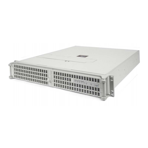
Preface This document, entitled RES-21XR3 for X8SAX Installation Manual, provides instructions on how to install, configure, power up, and boot the Themis Rugged Enterprise Server RES-21XR3 (see Figure 1), based on one 64-bit Intel Quad-Core 5500-Series or Quad/Six-Core 5600-Series Xeon CPU with a QPI (QuickPath Interconnect) up to 6.4 GT/s. -
Page 22: Figure 1-1 Res-21Xr3
RES-21XR3 for X8SAX Installation Manual Table 1. RES-x2XR3-S / RES-x1XR3 17” Chassis Manual Matrix (AC and DC Power Supplies) Mother- RES-32XR3-S RES-22XR3-S RES-12XR3-S RES-31XR3 RES-21XR3 RES-11XR3 board Manual P/N Manual P/N Manual P/N Manual P/N Manual P/N Manual P/N kets... -
Page 23: Table 2 Res-X2Xr3 20" Chassis Manual Matrix (Ac And Dc Power Supplies)
6 = SAS 2.0 y: LN4 = Extra gigabit Ethernet controller for two extra ports z: F = IPMI blank = No IPMI a—All motherboards measure 12”W x 13”L except X8DTN+ and X8DAH+-F, which are 13.68”W x 13” L. Themis Computer... -
Page 24: Table 3 Front I/O 16" Chassis Manual Matrix (Ac And Dc Power Supplies)
F = IPMI blank = No IPMI The 2RU-high (3.5”) RES-21XR3 has been designed to fit into a standard 19” rack and is provided with rack-mount brackets with handles. Optional rack-mount slides are also available. The RES-21XR3 is rugged enough to withstand extreme shock (up to 35G), vibration, temperature, and EMI as that associated with such demand- ing markets as the military, aerospace, and telecommunications industries. - Page 25 Preface Website Information • ICH1OR + PXH/V An overview of RES-21XR3 design and specifications is given in Chapter 1, "Over- view and Specifications", of this manual. This manual is intended for an experienced system administrator with a knowledge of both networking and high-speed server systems.
- Page 26 RES-21XR3 for X8SAX Installation Manual Caution: A caution describes a procedure or action that may result in damage to the equipment. This may involve—but is not restricted to—heavy equipment or sharp objects. To reduce the risk, follow the instructions accompanying this sym- bol.
-
Page 27: Overview And Specifications
1RES-21XR3 Overview and Specifications Overview The RES-21XR3 for X8SAX (see Figure 1-1; a block diagram is given in Figure 1-2, page 1-3) is a rack-mounted system designed for above-average shock and ® vibration environments. The RES-21XR3 supports a single Intel... -
Page 28: Table 1-1 Res-21Xr3 For X8Sax Motherboard Options
133/100 MHz PCI-X e—32-bit 33-Mhz PCI slots. The RES-21XR3 for X8SAX is designed within a 2RU-high (3.5”) form factor 17” (43.2 cm) deep and 17.07” (43.4 cm) wide (which, with mounting brackets, fits a 19”- wide rack). Major features of motherboards are listed in Table 1-2. -
Page 29: Figure 1-2 X8Sax Motherboard Block Diagram
ICH10R SATA x 6 PCI_32_BUS South Bridge USB2.0 PCI 32 x 1 Slot USB x 12 TI TSB43AB22A W83795ADG H/W Monitor W83627DHG LPC I/O SPI EEPRO M Realtek ALC883 Floppy COM1 COM2 Figure 1-2. X8SAX Motherboard Block Diagram Themis Computer... -
Page 30: Figure 1-3 External Features Of Res-21Xr3 For X8Sax (Front And Rear)
PCI-Express 2.0 x16 slot Figure 1-3. External Features of RES-21XR3 for X8SAX (Front and Rear) The RES-21XR3 for X8SAX front panel houses eight removable storage drive bays (see Figure 1-3). In addition, the front panel supports a CD-RW/DVD-ROM combo drive. The motherboard supports SATA drives only, but SAS drives may be sup- ported by optional I/O cards, hence a combination of both SATA and SAS drives may be installed. -
Page 31: System Leds And I/O Connectors
(cover removed) of Figure 1-4 on page 1-6. System LEDs and I/O Connectors All RES-21XR3 for X8SAX system LEDs are located on the front panel (see A, Fig- ure 1-5, page 1-7); all I/O connectors are located on the rear panel (see B, Figure 1-5). -
Page 32: Figure 1-4 Major Components Of Res-21Xr3 For X8Sax (Top View)
(PCI-Express 2.0 x16) * PCI-e x4 in a x8 slot. Breakaway View Lithium Battery (underneath deflector) 80-mm Fan (1 of 3) CD/DVD Disk Drive (1 of 8) Front Combo-Drive Housing Figure 1-4. Major Components of RES-21XR3 for X8SAX (Top View) Themis Computer... -
Page 33: Figure 1-5 Res-21Xr3 System Leds And I/O Connectors
LAN 2 Port LAN 1 Port Line-in I/O Connectors Front PS/2 Mouse PS/2 Keyboard Side-Surround USB7 (top) USB3 (top) USB6 (bottom) Microphone-in USB5 (top) USB0 (bottom) S/PDIF Port USB4 (bottom) Figure 1-5. RES-21XR3 System LEDs and I/O Connectors Themis Computer... -
Page 34: Table 1-3 System Leds
RES-21XR3 for X8SAX Installation Manual Table 1-3. System LEDs Symbol Description Power Indicates that the system is turned on. Storage Drive Indicates SAS/SATA storage-drive activity. NIC1 (Gb Ethernet) Indicates network activity on LAN 1. ENET1 < > ENET2 NIC2 (Gb Ethernet) Indicates network activity on LAN 2. -
Page 35: Table 1-4 I/O Connectors
1 and LAN 2. S/PDIF (Sony/Philips Digital Interface Format) (refer to “S/PDIF_Out S/PDIF Port Connector” in Appendix A.) High Definition Audio codec supports 7.1+2 Channel High Definition High Definition Audio (HDA) Audio. (refer to “High Definition Audio” in Appendix A) Themis Computer... -
Page 36: Chipset Overview
X8SAX motherboard provides the performance and feature sets required for single processor high-end systems, including optimal configuration options for intensive application and high-end server platforms. The RES-21XR3 for X8SAX supports a single 64-bit Intel 5500-Series/5600-Series Xeon processor in an LGA1366 socket with a QPI up to 6.4 GT/s. -
Page 37: Onboard Voltage Monitoring
When the CPU goes into a suspend state, the chassis power LED will start blinking to indicate that the CPU is in the suspend mode. When the user presses any key, the CPU will wake-up and the LED indicator will automatically stop blinking and remain on. 1-11 Themis Computer... -
Page 38: Bios Support For Usb Keyboard
RES-21XR3 for X8SAX Installation Manual 1.5.2 BIOS Support for USB Keyboard If the USB keyboard is the only keyboard in the system, it will function like a nor- mal keyboard during system boot-up. 1.5.3 Main Switch Override Mechanism When an ATX power supply is used, the power button can function as a system sus- pend button. - Page 39 The Super I/O provides functions that comply with ACPI (Advanced Configuration and Power Interface), which includes support of legacy and ACPI power manage- ment through a SMI or SCI function pin. It also features auto power management to reduce power consumption. 1-13 Themis Computer...
-
Page 40: Specifications
RES-21XR3 for X8SAX Installation Manual Specifications 1.7.1 General Table 1-5 lists general specifications for the RES-21XR3. Table 1-5. RES-21XR3 General Specifications Parameter Description Dimensions 3.5” (2RU) high 17.07” (43.4 cm) wide (19” rack-mountable) 17” (43.2 cm) deep Weight Approximately 22.5 pounds (10.2 kg), includes 1 CPU, 6 DIMMs, 2 full-length (up to 12.25”) PCI cards, 1 CD-RW/DVD-... -
Page 41: Electrical
= Not Applicable. 1.7.2.1 System Power The RES-21XR3 for X8SAX operates with two N+1 redundant AC power supplies of 750-watts capacity each that auto-range single-phase AC input from 100 to 265 VAC (47 to 63 Hertz) sources. Filtered and fused (internal) AC is supplied to each power supply from a rear-mounted power connection. -
Page 42: Environmental
The RES-21XR3 conforms to the 54-db noise specification. It is possible to achieve further noise reduction by installing a sound baffle (muffler) on both the front (see Figure 1-6) and the rear (see Figure 1-7 on page 1-17) of the RES-21XR3 chassis. Call your Themis representative for additional information. -
Page 43: Figure 1-7 Res-21Xr3 With Rear Sound Baffle Installed (Rear View)
Overview and Specifications Specifications Front Access—Opening the two front doors of the RES-21XR3 requires removing the front sound baffle. To do this, loosen the two (2) captive knurled Phillips screws holding the baffle to the chassis and remove the baffle. -
Page 44: Packaging And Shipping
AC power cords is 8.8 pounds (4 kg). The approximate weight of a RES-21XR3 (loaded with 1 CPU, 6 DIMMs, 2 storage drives, 2 full-length PCI cards, 1 CD-RW/DVD-ROM drive, and two power sup- plies) is approximately 22.5 pounds (10.2 kg). -
Page 45: Rack-Mount Slides (Optional)
1.8.2 Rack-Mount Slides (Optional) Rack-Mount Slides can be mounted on each side of the RES-21XR3 for the purpose of sliding the unit in and out of a rack. Mounting slides are optional and can be ordered at the time of purchase. - Page 46 RES-21XR3 for X8SAX Installation Manual Table 1-7. Approximate Weights of the RES Series Weight Model Depth Description (Approximate) Sockets RES-12XR3 19.5 lbs (8.9 kg) 20” Includes: All CPU sockets filled 6 DIMMs RES-12XR3-S 17 lbs (7.7 kg) 17” 2 storage drives...
-
Page 47: Installation And Operation
• How to install a memory module, storage drive, PCI card, 80-mm-fan, power supply, and lithium battery. • Rack-mount brackets and slides • How to turn the RES-21XR3 for X8SAX on and off Installation Procedures Caution: Use industry-standard ESD grounding techniques when handling all components. -
Page 48: Figure 2-1 Remove The Res-21Xr3 Protective Access Cover
1. Loosen the two captive Phillips screws holding the protective top access cover to the rear of the RES-21XR3 chassis (see A, Figure 2-1). 2. Both the front and sides of the cover have flat hooks or tabs underneath that fit under slots on the chassis top edges (see B, Figure 2-1). -
Page 49: Memory Modules
2.1.2 Memory Modules The RES-21XR3 for X8SAX supports memory according to Table 2-1. Note the total memory capacity is dependent on the size of the memory modules, which at the present time is restricted to 4 GB each. Obviously, memory capacity will increase as motherboards are designed to handle increased sizes (8-GB and 16-GB DIMMs, for example). - Page 50 RES-21XR3 for X8SAX Installation Manual Figure 2-3 on page 2-6), and all Bank 1 slots (1A, 2A, and 3A) must be filled before populating any Bank 2 slots (1B, 2B, and 3B) • It is strongly recommended that you do not mix memory modules of different speeds, sizes, and vendors.
-
Page 51: Installation
After the air-flow diverter has been removed, the memory module slots will be exposed (see Figure 2-3). Figure 2-2. Remove the Air-Flow Deflector Screws Themis Computer... -
Page 52: Figure 2-3 Memory Module Slot Locations
RES-21XR3 for X8SAX Installation Manual CPU Socket Bank 1 Slots: 1A, 2A, 3A Bank 2 Slots: 1B, 2B, 3B DIMM 1B Branch 0 DIMM 1A DIMM 2B Branch 1 DIMM 2A DIMM 3B Branch 2 DIMM 3A Figure 2-3. Memory Module Slot Locations 2. -
Page 53: Pci Cards
4. If all the memory modules have been replaced in the system, replace the air flow diverter and secure it with the seven screws previously removed. 2.1.3 PCI Cards RES-21XR3 for X8SAX supports six (6) PCI slots, as defined in Figure 2-5). All Themis Computer... -
Page 54: Installing Cards
PCI Express 2.0 x16 Slot PCI-Express 2.0 x4 in an x8 Slot PCI Express 2.0x16 Slot Figure 2-5. RES-21XR3 for X8SAX PCI Card Installation 2.1.3.1 Installing Cards Perform the following steps to install a PCI card: 1. Loosen the captive knurled screw on the PCI card clamp (see A, Figure 2-6). -
Page 55: Lithium Battery
7. Attach any internal I/O cables to the installed PCI cards, and carefully fold and tuck any exposed ribbon cables into the cabinet. 8. If you have no further installations to perform, close the RES-21XR3 chassis by refastening the top cover removed in Section 2.1.1, “Remove Protective Top Cover,”... -
Page 56: Installing A Lithium Battery
2. Carefully press down on the battery until it clicks firmly into place. 2.1.5 SAS/SATA Storage Drive Perform the following to remove and install a hard-disk/solid-state drive. The front doors of the RES-21XR3 must be unlocked and opened to access the drives (see Fig- 2-10 Themis Computer... -
Page 57: Opening The Res-21Xr3 Front Doors
(ID0) is designated as the boot drive. 2.1.5.1 Opening the RES-21XR3 Front Doors The knurled captive screw on the front of the RES-21XR3 for X8SAX allows the doors to lock without a key. To unlock the doors, turn the screw counterclockwise and pull both doors away from the chassis. -
Page 58: Storage-Drive Removal
After opening the front doors, perform the following steps to remove and install a hard-disk/solid-state drive: Note: Since RES-21XR3 for X8SAX disk drives are “hot-swappable”, it is not necessary to turn off system power in order to remove and replace a drive (except the operating system drive). -
Page 59: Storage-Drive Installation
The handle will swing closed when it comes into contact with the RES-21XR3 chassis. 4. When the drive is fully inserted in its slot, insert the key into the barrel lock and turn it 45 degrees counter-clockwise. -
Page 60: Hot-Swappable 80-Mm Fan
With the right hand-index finger (or left-hand thumb), press on the right- hand side of the fan and pull the fan directly upward from the RES-21XR3 chassis. -
Page 61: Power Supply
3. Squeeze the locking lever toward the extraction handle and firmly pull the power supply from the chassis (see B, Figure 2-12). Caution: When pulling the power supply from the chassis, hold it at the bot- tom to prevent it from falling and damaging the unit. 2-15 Themis Computer... -
Page 62: Installing A Power Supply
Extraction Handle Figure 2-12. The RES-21XR3 Power Supply Locking Mechanism 2.1.7.2 Installing a Power Supply Perform the following steps to install a power supply: 1. Insert the replacement power supply into an empty slot with the power LED at the top (see Figure 2-12). -
Page 63: Rack Mounts
To learn how to install rack-mount slides, refer to Appendix B, “Rack-Mount Slide Installation”. Caution: Any screws used to mount a slide to a RES-21XR3 chassis must not ex- ceed a length of 3/8” to prevent excessive penetration of the chassis. -
Page 64: Operation
Before powering on the RES-21XR3, plug in the AC power cords as follows: 1. On the rear of the RES-21XR3, plug an AC power cord (shipped with unit) into the AC power socket on each power supply (see Figure 2-14). -
Page 65: Getting Started
Installation and Operation Operation 2. On the front of the RES-21XR3, push the system power on/off button (see Figure 2-15). This will cause the system POWER LED to light (green). Power LED System Power On/Off Button Figure 2-15. System Power Button and LED on the RES-21XR3 Front 2.3.3... -
Page 66: Turning The System Off
1. To turn the RES-21XR3 power off, press and hold the system power on/off button (see Figure 2-15, page 2-19) for at least four (4) seconds. This will shut down the system and turn off the POWER LED. -
Page 67: Bios Setup Utility
The right frame displays the key legend. Above the key legend is an area reserved for a text message. When an option is selected in the left frame, it is highlighted in white. Often a text message will accompany it. Themis Computer... -
Page 68: How To Change The Configuration Data
RES-21XR3 for X8SAX Installation Manual Note: The AMI BIOS has default text messages built in. Themis Computer re- tains the option to include, omit, or change any of these text messages. The AMI BIOS Setup Utility uses a key-based navigation system called “hot keys”. -
Page 69: Main Bios Setup
<Enter>. Press the <Tab> key to move between fields. The date must be entered in Day MM/DD/YY format. The time is entered in HH:MM:SS format. Note: The time is in the 24-hour format. For example, 5:30 P.M. appears as 17:30:00. Themis Computer... -
Page 70: Ambios
RES-21XR3 for X8SAX Installation Manual 3.2.2 AMBIOS • Version: This item displays the BIOS revision used in your system. • Build Date: This item displays the date when this BIOS was completed. 3.2.3 Processor The AMI BIOS will automatically display the status of the processor used in your system: •... -
Page 71: Advanced Setup Configurations
This option allows the bootup screen options to be modified between POST mes- sages or the OEM logo. Select Disabled to display the POST messages. Select Enabled to display the OEM logo instead of the normal POST messages. The options are Enabled (default) and Disabled. Themis Computer... -
Page 72: Addon Rom Display Mode
RES-21XR3 for X8SAX Installation Manual 3.3.1.3 AddOn ROM Display Mode This sets the display mode for Option ROM. The options are Force BIOS (default) and Keep Current. 3.3.1.4 Bootup Num-Lock This feature selects the Power-on state for the Numlock key. The options are Off and On (default). -
Page 73: Interrupt 19 Capture
Select Enable to use the feature of Clock Spectrum, which will allow the BIOS to monitor and attempt to reduce the level of Electromagnetic Interference caused by the components whenever needed. The options are Disabled (default) and Enabled. Themis Computer... -
Page 74: Hardware Prefetcher (Available When Supported By The Cpu)
RES-21XR3 for X8SAX Installation Manual 3.3.2.3 Hardware Prefetcher (Available when supported by the CPU) If set to Enabled, the hardware prefetcher will prefetch streams of data and instruc- tions from the main memory to the L2 cache in the forward or backward manner to improve CPU performance. -
Page 75: Intel Aes-Ni (When Supported By The Cpu)
CPU's power consumption by reducing the CPU's clock cycle and voltage during a “Halt State.” The options are Disabled and Enabled (default). 3.3.2.14 C-STATE Tech If enabled, C-State is set by the system automatically to either C2, C3, or C4 state. The options are Disabled and Enabled (default). Themis Computer... -
Page 76: C-State Package Limit Setting
RES-21XR3 for X8SAX Installation Manual 3.3.2.15 C-State Package Limit Setting If set to Auto, the AMI BIOS will automatically set the limit on the C-State package register. The options are Auto (default), C1, C3, C6, and C7. 3.3.2.16 C1 Auto Demotion When enabled, the CPU will conditionally demote C3, C6, or C7 requests to C1 based on un-core auto-demote information. -
Page 77: Qpi & Imc Configuration
The options are Independent (default), Channel Mirror, Lockstep, and Sparing. • Independent - All DIMMs are available to the operating system. • Channel Mirror - The motherboard maintains two identical copies of all data in memory for redundancy. 3-11 Themis Computer... -
Page 78: Demand Scrubbing
RES-21XR3 for X8SAX Installation Manual • Lockstep - The motherboard uses two areas of memory to run the same set of operations in parallel. • Sparing - Memory sparing occurs when on-demand inactive memory is auto- matically activated by the system to temporarily replace failed memory until a service action can be performed (supported only on 2010 Intel®... -
Page 79: Sr-Iov Support
The Options are: Disabled, 2 USB ports, 4 USB ports, 6 USB ports, 8 USB ports, 10 USB ports, and 12 USB ports (default). 3.3.3.18 USB 2.0 Controller Select Enabled to activate the onboard USB 2.0 controller. The options are Enabled (default) and Disabled. 3-13 Themis Computer... -
Page 80: Legacy Usb Support
RES-21XR3 for X8SAX Installation Manual 3.3.3.19 Legacy USB Support Select Enabled to use Legacy USB devices. If this item is set to Auto, Legacy USB support will be automatically enabled if a legacy USB device is installed on the motherboard, and vice versa. The settings are Disabled, Enabled, and Auto (default). -
Page 81: Primary Ide Master/Slave, Secondary Ide Master/Slave, Third Ide Master, And Fourth Ide Master
Select 0 to allow the AMI BIOS to use PIO mode 0. It has a data transfer rate of 3.3 MB/s. Select 1 to allow the AMI BIOS to use PIO mode 1. It has a data transfer rate of 5.2 MB/s. 3-15 Themis Computer... -
Page 82: Dma Mode
RES-21XR3 for X8SAX Installation Manual Select 2 to allow the AMI BIOS to use PIO mode 2. It has a data transfer rate of 8.3 MB/s. Select 3 to allow the AMI BIOS to use PIO mode 3. It has a data transfer rate of 11.1 MB/s. -
Page 83: Pci/Pnp Configuration
This feature sets the latency Timer of each PCI device installed on a PCI bus. Select 64 to set the PCI latency to 64 PCI clock cycles. The options are 32, 64 (default), 96, 128, 160, 192, 224 and 248. 3-17 Themis Computer... -
Page 84: Pcix Slot Frequency
RES-21XR3 for X8SAX Installation Manual 3.3.5.4 PCIX Slot Frequency This feature selects the maximum PCI bus speed. When Auto is selected, the bus speed is determined automatically by the system based on the capability of the device attached to the bus. The options are Auto, 33MHz PCI, 66MHz PCI, 66MHz PCI-X M1, 100 MHz PCI-X M1, and 133 MHz PCI-X M1. -
Page 85: Super Io Device Configuration
Serial Port Mode This feature allows the user to set the serial port mode for Console Redirection. The options are 115200 8, n 1 (default); 57600 8, n, 1; 38400 8, n, 1; 19200 8, n, 1; and 3-19 Themis Computer... -
Page 86: Hardware Health Configuration
RES-21XR3 for X8SAX Installation Manual 9600 8, n, 1. Flow Control This feature allows the user to set the flow control for Console Redirection. The options are None (default), Hardware, and Software. Redirection After BIOS POST Select Disabled to turn off Console Redirection after Power-On Self-Test (POST). -
Page 87: Cpu Overheat Alarm
CPU is still within its normal operating state and below the CPU ‘Tem- perature Tolerance’. The motherboard fans and CPU will run normally as con- 3-21 Themis Computer... - Page 88 RES-21XR3 for X8SAX Installation Manual figured in the BIOS. The fans may adjust to a faster speed depending on the Fan Speed Control settings. User Intervention: No action is required. However, consider checking the fans and the chassis ventilation for blockage.
-
Page 89: Ioh Temperature
Select Energy Saving for the onboard fans to run at 30% of the Initial PWM Cycle for best power efficiency and maximum quietness. The Options are: Full Speed/FS (@100% of PWM Cycle) (default), Performance/PF (@70% of PWM Cycle), Balanced/BL (@50% of PWM Cycle), and Energy Saving/ES 3-23 Themis Computer... -
Page 90: Voltage Reading
RES-21XR3 for X8SAX Installation Manual (@30% of PWM Cycle). 3.3.8.7 Voltage Reading This feature displays the current voltage detected of the various components in the system: Vcore, VDIMM, 5V, 12V, -12V, 3.3 Vcc, 3.3VSB, VBAT, Vtt 3.3.9 ACPI Configuration Use this feature to configure Advanced Configuration and Power Interface (ACPI) power management settings for your system. -
Page 91: Ami Oemb Table
3.3.10.2 Mark all Events as Read This option marks all events as read. The options are OK and Cancel. 3.3.10.3 Clear Event Log This option clears the Event Log memory of all messages. The options are OK and Cancel (default). 3-25 Themis Computer... -
Page 92: Pcie Error Log
RES-21XR3 for X8SAX Installation Manual 3.3.10.4 PCIe Error Log Use this option to enable logging of errors encountered in the system's PCIe bus. The options are Yes (default) and No. 3.3.10.5 Memory ECC Error Log Use this option to enable logging of errors encountered in the system’s memory. The options are Yes and No. -
Page 93: User Password
Password has been set) This item allows you to clear a user password after it has been entered. Password Check This item allows you to check a password after it has been entered. The options are Setup (default) and Always. 3-27 Themis Computer... -
Page 94: Boot Sector Virus Protection
RES-21XR3 for X8SAX Installation Manual 3.4.6 Boot Sector Virus Protection When Enabled, the AMI BIOS displays a warning when any program (or virus) issues a Disk Format command or attempts to write to the boot sector of the storage drive. The options are Enabled and Disabled (default). -
Page 95: Hard Disk/Solid State Drives
This feature allows the user to specify the boot sequence from available CD/DVD Drives, (i.e., 1st Drive, 2nd Drive, etc.) Exit Options Select the Exit tab from the AMI BIOS Setup Utility screen to enter the Exit BIOS Setup screen. Figure 3-5. Exit Options 3-29 Themis Computer... -
Page 96: Save Changes And Exit
RES-21XR3 for X8SAX Installation Manual 3.6.1 Save Changes and Exit When you have completed the system configuration changes, select this option to leave the BIOS Setup Utility and reboot the computer so that the new system config- uration parameters can take effect. -
Page 97: Bios Recovery
Flashing the wrong BIOS can cause irreparable damage to the system. In no event shall Themis Computer be liable for direct, indirect, special, incidental, or conse- quential damages arising from a BIOS update. If you need to update the BIOS, do not shut down or reset the system while the BIOS is updating. -
Page 98: Part 2-Bios Reprogramming (Re-Flashing)
RES-21XR3 for X8SAX Installation Manual being reprogrammed. The screen will also display a message as shown below. DO NOT INTERRUPT THIS PROCESS! Figure 3-6. Flash Recovery 5. When the Boot Sector Recovery Process is complete, the system will reboot automatically and you will see a checksum error on your screen. - Page 99 USB Device/Drive (above) starting from Step 3 and continue on to Part 2 - BIOS Reprogramming (Re-Flashing). If your system still does not boot up after performing the above procedure, then there may be other issues with your motherboard. Please contact your Themis Customer Service representative. 3-33...
- Page 100 RES-21XR3 for X8SAX Installation Manual 3-34 Themis Computer...
-
Page 101: Appendix A. Connector Pinouts
I/O panel of the RES-21XR3 for X8SAX. PS/2 Keyboard and Mouse The RES-21XR3 for X8SAX provides a 6-pin female mini-DIN connector for the PS/2 keyboard, and another for the PS/2 mouse. Pinouts and signal definitions for both connectors are defined in Table A-1. -
Page 102: Usb Ports
RES-21XR3 for X8SAX Installation Manual USB Ports The RES-21XR3 for X8SAX supports eight USB (Universal Serial Bus) port con- nectors (see Figure A-1 for a connector pinout), USB 0 through USB 7, on the rear I/ O panel. Signal descriptions are listed in Table A-2. -
Page 103: High Definition Audio
L&R, rear L&R, center, and sub- woofer speakers. Use the software included in the CD-ROM that came with your RES-21XR3 to enable this function. The RES-21XR3 supports six sub-miniature (3.5-mm diameter) audio ports:... -
Page 104: S/Pdif_Out Connector
RES-21XR3 for X8SAX Installation Manual The microphone jack will support most types (dynamic, condenser, etc.) of micro- phones now on the market. S/PDIF_Out Connector An S/PDIF_Out connector is located next to the Backpanel USB ports on the moth- erboard. The S/PDIF (Sony/Philips Digital Inteface Format) connector is used for transporting stereo digital audio signals. -
Page 105: Table A-5 S/Pdif Bottom Component Pin Definition
S/PDIF_Out Connector Table A-4. S/PDIF_RCA Pin Definitions S/PDIF_RCA (Top Component) Pin Definition Location Definition 5: Outside Ground 4: Inside S/PDIF Signal Table A-5. S/PDIF Bottom Component Pin Definition S/PDIF (Bottom Component) Pin Definition Pin # Definition Ground S/PDIF Signal Themis Computer... - Page 106 RES-21XR3 for X8SAX Installation Manual Themis Computer...
-
Page 107: Appendix B. Rack-Mount Slide Installation
An optional set of two rack-mount slides (left side and right side) is available for all RES 2RU-high systems, and should be ordered at the time of purchase. The RES-21XR3 chassis contains six threaded screw holes on each side to accommodate #8-32 size screws (included with the rack-mount slide kit); steel slides require four mounting holes, and aluminum slides require three mounting holes (see Figure B-1). - Page 108 Push the system into the rack until the mounting brackets on the front of the chassis are flush with the front of the rack. 5. Secure the RES-21XR3 system to the 19” rack with two bolts on each side. Themis Computer...
- Page 109 (included in slide kit) Attach both inside slide sections to the left and right sides of the RES-21XR3 chassis with #8-32 screws (included in slide kit) Figure B-2. RES-21XR3 for X8SAX Rack-Mount Slide Installation Themis Computer...
- Page 110 RES-21XR3 for X8SAX Installation Manual Themis Computer...
-
Page 111: Appendix C. Red Hat Enterprise Linux 5 Installation
Welcome to the Red Hat ® Enterprise Linux ® Installation Guide. This guide contains useful information to assist you during the installation of Red Hat Enterprise Linux via DVD device, from fundamental concepts such as installation preparation to the step-by-step installation procedure. Themis Computer... -
Page 112: Installation
RES-21XR3 for X8SAX Installation Manual Installation C.2.1 Step 1. Figure C-1. Power On after Linux DVD is Inserted into Drive Step 1: Insert the Redhat Enterprise Linux 5 DVD and Power on the system; you will see the first installation screen with a boot prompt, press “ENTER” to begin installation (see Figure C-1 on page C-2). -
Page 113: Figure C-3 Welcome Screen
The installation program tries to define the appropriate time zone based on what you specify on this screen. Once you have made the language selection, click Next to continue. (see Figure C-4 on page C-3) Themis Computer... -
Page 114: Step 6
RES-21XR3 for X8SAX Installation Manual C.2.5 Step 5 Figure C-5. Selecting Layout Type Step 5: Using your mouse, select the correct layout type (for example, U.S. English) for the keyboard you would prefer to use for the installation and as the sys- tem default. -
Page 115: Step 7
You can configure an iSCSI target for installation, or disable a dmraid device from this screen by clicking on the 'Advanced storage configuration' button (see Figure C-7 on page C-5). Click Next to continue. Themis Computer... -
Page 116: Step 8
RES-21XR3 for X8SAX Installation Manual C.2.8 Step 8 Figure C-8. Reviewing Option Step 8: Create default layout allows you to have some control concerning what data is removed (if any) from your system. Your options are: • Remove all partitions on selected drives and create default layout — select this option to remove all partitions on your hard drive(s) (this includes partitions created by other operating systems such as Windows VFAT or NTFS partitions). -
Page 117: Step 9
Red Hat Enterprise Linux. This is done by defining mount points for one or more disk partitions in which Red Hat Enterprise Linux is installed. You may also need to create and/or delete partitions at this time (see Figure C-9 on page C-7). Click Next. Themis Computer... -
Page 118: Figure C-10 Setting Up Boot Loader
RES-21XR3 for X8SAX Installation Manual C.2.10 Step 10 Figure C-10. Setting Up Boot Loader Step 10: Once you have configured your partitions, set up a boot loader. If you select “No Boot Loader will be Installed,” you’ll need to use a third-party boot loader such as Partition Magic or Microsoft’s TLDR. -
Page 119: Figure C-11 Master Boot Record (Mbr
In this case, your other boot loader takes control first. You can then configure that boot loader to start GRUB, which then boots Red Hat Enterprise Linux. If your system only uses Red Hat Enterprise Linux, you should choose the MBR. Themis Computer... -
Page 120: Figure C-12 Network Devices List
RES-21XR3 for X8SAX Installation Manual Click the Change Drive Order button if you would like to rearrange the drive order or if your BIOS does not return the correct drive order. Changing the drive order may be useful if you have multiple SCSI adapters, or both SCSI and IDE adapters, and you want to boot from the SCSI device. -
Page 121: Figure C-13 Edit Interface Pop-Up Screen
If you select Activate on boot, your network interface is started when you boot (see Figure C-13 on page C-11). If you do not have DHCP client access or you are unsure what to provide here, please contact your network administrator. Click OK. C-11 Themis Computer... -
Page 122: Figure C-14 Selecting Time Zone
RES-21XR3 for X8SAX Installation Manual C.2.14 Step 14 Figure C-14. Selecting Time Zone Step 14: Set your time zone by selecting the city closest to your computer's physical location. Click on the map to zoom in to a particular geographical region of the world (see Figure C-14 on page C-12). -
Page 123: Figure C-15 Setting Up Root Account And Password
Your root account is similar to the administrator account used on Windows NT machines. The root account is used to install packages, upgrade RPMs, and perform most system maintenance. Logging in as root gives you complete control over your system (see Figure C-15 on page C-13). Click Next. C-13 Themis Computer... -
Page 124: Figure C-16 Package Installation Default Screen
RES-21XR3 for X8SAX Installation Manual C.2.16 Step 16 Figure C-16. Package Installation Default Screen Now that you have made most of the choices for your installation, you are Step 16: ready to confirm the default package selection or customize packages for your sys- tem. -
Page 125: Figure C-17 Optional Packages
Optional packages to view which packages are installed by default, and to add or remove optional packages from that group (see Figure C-17 on page C-15). If there are no optional components this button will be disabled. Click Next. C-15 Themis Computer... -
Page 126: Step 19
RES-21XR3 for X8SAX Installation Manual C.2.18 Step 18 Figure C-18. Option to Review or Continue Step 18: Once you have selected the package groups of your choice, you get one last chance to go back before starting the installation process. Click Next if you’re happy with your choices, or click Back to make changes (see Figure C-18 on page C-16). -
Page 127: Step 20
• Do nothing — after the boot loader's time-out period, (by default, five seconds) the boot loader automatically boots the default boot entry. Do whatever is appropriate to boot Red Hat Enterprise Linux. One or more screens of messages should scroll by. C-17 Themis Computer... -
Page 128: Step 21
RES-21XR3 for X8SAX Installation Manual C.2.21 Step 21 Figure C-21. Login Screen Eventually, a prompt or a GUI login screen appears (if you installed Step 21: login: the X Window System and chose to start X automatically). (see Figure C-21 on page C-18). -
Page 129: Appendix D. Optional Remote On/Off Switch
Customers interested in installing an optional switch from which to remotely turn the RES-21XR3 on or off are able to order a Remote On/Off Switch module that is easily installed in an available storage-drive bay (see Figure D-1, which shows the Remote On/Off Switch installed in an RES-32XR3/FIO system). -
Page 130: Ordering The Remote On/Off Switch
When operational, if the RES-21XR3 is turned OFF, pressing the remote switch ON will turn the system on. If the RES-21XR3 is turned ON, pressing the switch OFF for less than 4 seconds will gracefully shut down the system through the BIOS; pressing the switch OFF for 4 seconds or more results in a “hard”... -
Page 131: Appendix E. Re-Packing Instructions
Re-Packing Instructions Re-Packaging for Shipment If it becomes necessary to return equipment to Themis Computer, it is very impor- tant that the equipment be shipped in packaging that provides adequate protection against crushing and moisture invasion. The original packaging is best for this pur- pose, provided the packaging is retained in serviceable condition. -
Page 132: Instructions For Re-Packing
RES-21XR3 for X8SAX Installation Manual side with the plastic membrane is against the equipment. Top Layer RES Equipment goes between the membranes Membrane Bottom Layer Packing Container Figure E-1. Packaging Components Instructions for Re-Packing Re-assemble the packing material about the equipment in accordance with the fol- lowing instructions: (See Figure E-2. - Page 133 • Seal the top of the box with strong packing tape, wrapping the tape completely around the box, both lengthwise, and crosswise. • Prepare for shipment in accordance with the instructions received from Themis Computer. Figure E-2.
- Page 134 RES-21XR3 for X8SAX Installation Manual Themis Computer...
-
Page 135: Index
Remote Access Configuration 3-19 Chipset Overview 1-10 Super IO Device Configuration 3-19 Clear Event Log 3-25 Advanced Setup Clear NVRAM 3-17 Configurations 3-5 Clear User Password 3-27 antistatic bags 2-1 Clock Spread Spectrum 3-7 antistatic wrist strap 2-1 Index-1 Themis Computer... - Page 136 RES-21XR3 for X8SAX Installation Manual COM1 / COM2 serial port/header 1-9 Fan Status Monitor with Firmware Control 1-11 Comments xxiii Fan1—Fan 5 Reading 3-23 components, major 1-5 Features of the LGA 1366 Processor and the Configuration, system 2-19 X58 1-10...
- Page 137 3-3 Installation procedures 2-1 Main Switch Override Mechanism 1-12 installing rack-mount slides B-1 Major Components of the RES-21XR3 for memory modules 2-5 X8SAX Motherboards (Top View) 1-6 PCI cards 2-8 Mark all Events as Read 3-25...
- Page 138 RES-21XR3 for X8SAX Installation Manual QPI Frequency 3-11 Password Check 3-27 QPI Links Speed 3-11 Patrol Scrubbing 3-12 Quick Boot 3-5 PC Health Monitoring 1-10 Quiet Boot 3-5 PCI cards 2-1, 2-7 PCI IDE BusMaster 3-18 PCI Latency Timer 3-17 rack-mount brackets 1-2, 2-17 PCI Slot 1—PCI Slot 6 3-18...
- Page 139 Turning the System On 2-18 Altitude 1-14 BTU Rating 1-15 Dimensions 1-14 Ultra320 SAS/SATA storage drives 1-2 Electrostatic Discharge 1-16 Unlocking the RES-21XR3 Storage Drives 2-11 Input Current 1-15 USB 2.0 Controller 3-13 Input Frequency 1-15 USB Functions 3-13 Input Leakage 1-15...
- Page 140 RES-21XR3 for X8SAX Installation Manual vibration xxii View Event Log 3-25 VT-UTF8 Combo Key Support 3-20 Wait For 'F1' If Error 3-6 Wake-On-LAN (WOL) 1-12 Warnings xxiii Watch Dog Function 3-6 Website Information xxiii Xeon processors 1-1, 1-2, 1-10 Index-6...
- Page 141 Place Stamp Here Themis Computer 47200 Bayside Parkway Fremont, CA 94538 Attn: Publications Department Fold here; tape at top to seal...
-
Page 142: Reader Comment Card
Reader Comment Card We welcome your comments and suggestions to help improve the RES-21XR3 for X8SAX Installation Manual. Please take time to let us know what you think about this manual. •Information provided in the manual was complete. Agree___ Disagree___ Not Applicable___ •Information was well documented and easy to follow.
Need help?
Do you have a question about the RES-21XR3 and is the answer not in the manual?
Questions and answers