
Related Manuals for Themis RES - 32XR3


Summary of Contents for Themis RES - 32XR3
- Page 1 User Manual User Manual Installation Installation Manual Manual 3RU 19” Rack-Mount Rugged Enterprise Server with X8DTi/X8DTi-F/X8DTi-LN4F Motherboard Configuration / Two Quad-Core 5500 or Quad/Six-Core 5600 Xeon CPUs...
- Page 3 RES-32XR3 Installation Manual - Configuration 2* Version 1.0— July 2010 * SuperMicro Motherboards X8DTi / X8DTi-F / X8DTi-LN4F Themis Computer—Americas and Pacific Rim Themis Computer—Rest of World 47200 Bayside Parkway 5 Rue Irene Joliot-Curie Fremont, CA 94538 38320 Eybens, France...
-
Page 4: Safety Precautions
Themis Computer assumes no responsibility for inaccuracies. Themis Computer retains the right to make changes to this publication at any time without prior notice. Themis Computer does not assume any liability arising from the application or use of this publication or the product(s) described herein. - Page 5 RES-32XR3 Installation Manual - Configuration 2 Version Revision History Version 1.0 ..................... July 2010 Themis Computer...
-
Page 6: Safety Instructions
In these cases, the device must be shut down and secured against unintentional operation. • Repairs may only be carried out by a person authorized by Themis Computer. • The device may only be opened for the installation and removal of extension... -
Page 7: Grounding Methods
4. Store electrostatic-sensitive boards in protective packaging or on conductive foam. Grounding Methods Guard against electrostatic damage at workstations by following these steps: 1. Cover workstations with approved anti-static material. Provide a wrist strap connected to a work surface and properly grounded tools and equipment. Themis Computer... - Page 8 Systems are equipped with a lithium battery installed on the motherboard. To replace this battery, please observe the instructions that are described in this man- ual. Warning: There is a danger of explosion when the wrong type of battery is used as a replacement. Themis Computer...
-
Page 9: Table Of Contents
1.9.2.2 Output Voltage ................1-16 1.9.3 Environmental ..................1-17 1.9.3.1 Shock ..................1-17 1.9.3.2 Electrostatic Discharge ............. 1-17 1.9.3.3 Noise ..................1-17 1.10 Packaging and Shipping ..................1-19 1.10.1 Accessory Kit ................... 1-19 1.10.2 Rack-Mount Slides (Optional) ..............1-20 Themis Computer... - Page 10 3.1 Introduction ......................3-1 3.1.1 Starting BIOS Setup Utility ............... 3-1 3.1.2 How To Change the Configuration Data ........... 3-2 3.1.3 Starting the Setup Utility ................3-2 3.2 Main Setup ......................3-3 3.2.1 System Overview ..................3-3 viii Themis Computer...
- Page 11 3.3.3.10 Clock Spread Spectrum .............. 3-9 3.3.4 Advanced Chipset Control ................. 3-9 3.3.5 QPI Links Speed ..................3-9 3.3.5.1 QPI Frequency ................3-9 3.3.5.2 QPI L0s and L1 ................3-9 3.3.5.3 Memory Frequency ..............3-9 3.3.5.4 Memory Mode ................3-9 Themis Computer...
- Page 12 3.3.9.4 PCI IDE Bus Master ..............3-17 3.3.9.5 Slot 1 Option ROM~Slot 6 Option ROM ......... 3-17 3.3.9.6 LAN1 PXE/LAN2 PXE/LAN3 PXE/LAN4 PXE (-LN3 PXE/-LN4 PXE: for LN4 models only) ......3-17 3.3.10 Super IO Device Configuration ............... 3-18 Themis Computer...
- Page 13 3.3.17 Set LAN Configuration ................3-25 3.3.17.1 Channel Number ............... 3-25 3.3.17.2 Channel Number Status ............3-25 3.3.17.3 IP Address Source ..............3-25 3.3.18 IP Address Configuration ................ 3-25 3.3.18.1 Parameter Selector ..............3-25 3.3.18.2 IP Address ................. 3-26 Themis Computer...
- Page 14 3.5.4 CD/DVD Drives ..................3-32 3.6 Exit Options ......................3-32 3.6.1 Save Changes and Exit ................3-33 3.6.2 Discard Changes and Exit ................ 3-33 3.6.3 Discard Changes ..................3-33 3.6.4 Load Optimal Defaults ................3-33 3.6.5 Load Fail-Safe Defaults ................3-33 Themis Computer...
- Page 15 D.2 Remote On-Only Configuration ................B-2 D.3 Ordering the Remote On/Off Switch ..............B-2 Appendix E. Re-Packing Instructions ................E-1 E.1 Re-Packaging for Shipment ...................E-1 E.2 Packing Components .....................E-1 E.3 Instructions for Re-Packing ...................E-2 Index ........................ Index-1 Reader Comment Card xiii Themis Computer...
- Page 16 RES-32XR3 Installation Manual - Configuration 2 Themis Computer...
- Page 17 Figure 2-15 System Power Button and LED on the RES-32XR3 Front ......2-16 Figure 3-1 Main BIOS Setup Screen ................. 3-3 Figure 3-2 Advanced Settings Screen ................3-5 Figure 3-3 Security Settings .................... 3-29 Figure 3-4 Boot Settings....................3-31 Themis Computer...
- Page 18 Figure C-14 Selecting Time Zone ..................C-14 Figure C-15 Setting Up Root Account and Password............C-15 Figure C-16 Package Installation Default Screen .............. C-16 Figure C-17 Optional Packages..................C-17 Figure C-18 Option to Review or Continue ............... C-18 Themis Computer...
- Page 19 PS/2 Keyboard/Mouse Pinouts ..............A-1 Table A-2 USB Connector Pinout Signal Descriptions ..........A-2 Table A-3 COM 1 Serial Connector Pinout Signal Descriptions ........A-2 Table A-4 RES-32XR3 SVGA Connector-Pin Signals ..........A-3 Table A-5 RJ45 Ethernet Pinout Signals ................ A-4 xvii Themis Computer...
- Page 20 RES-32XR3 Installation Manual - Configuration 2 xviii Themis Computer...
-
Page 21: Preface
Preface This document, entitled RES-32XR3 Installation Manual—Configuration 2, pro- vides instructions on how to install, configure, power up, and boot the Themis Rug- ged Enterprise Server RES-32XR3 (see Figure 1), based on two 64-bit Intel 5500- Series Xeon Quad-Core processors or two Intel 5600-Series Xeon Quad-to-Six- Core processors. - Page 22 6 = SAS 2.0 y: LN4 = Extra gigabit Ethernet controller for two extra ports z: F = IPMI blank = No IPMI a—All motherboards measure 12”W x 13”L except X8DTN+ and X8DAH+-F, which are 13.68”W x 13” L. Themis Computer...
- Page 23 T = Graphics chip; no sound chip w: Not applicable x: i = SATA only 3 = SAS 1.0 6 = SAS 2.0 y: LN4 = Extra gigabit Ethernet controller for two extra ports z: F = IPMI blank = No IPMI Themis Computer...
-
Page 24: Figure
3 = SAS 1.0 6 = SAS 2.0 y: LN4 = Extra gigabit Ethernet controller for two extra ports z: F = IPMI blank = No IPMI Figure 2. Front View of a Standard Rear-I/O RES-32 Chassis (Doors Removed) xxii Themis Computer... - Page 25 Preface Figure 3. Rear View of a Standard Rear-I/O RES-32 Chassis Figure 4. Front View of a Front-I/O RES-32 Chassis Figure 5. Rear View of a Front-I/O RES-32 Chassis xxiii Themis Computer...
- Page 26 This manual is intended for an experienced system administrator with a knowledge of both networking and high-speed server systems. Website Information Themis Computer corporate and product information may be accessed on the World Wide Web by browsing the website http://www.themis.com. Your Comments are Welcome We are interested in improving our documentation and welcome your comments and suggestions.
- Page 27 To reduce the risk, follow the instructions accompanying this sym- bol. Sidebar: A “sidebar” adds detail to the section within which it is placed, but is not absolutely vital to the description or procedure of the section. Themis Computer...
- Page 28 RES-32XR3 Installation Manual - Configuration 2 xxvi Themis Computer...
-
Page 29: Overview And Specifications
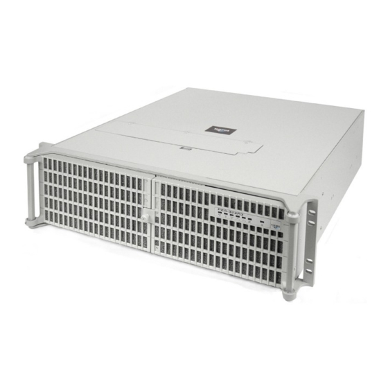
(with QPI up to 6.4 GT/s) with up to 192 GB of DDR3 ECC Registered mem- ory, and has many computer- and graphics-intensive and diverse-I/O capabilities, ideal for military/aerospace and commercial telecommunications applications. Options supported by the RES-32XR3 are listed in Table 1-1 on page 1-2. Figure 1-1. RES-32XR3 Configuration 2 Themis Computer... -
Page 30: Table 1-1 Res-32Xr3 Configuration 2 Motherboard Options
Left and right rack-mount tabs are attached to the chassis Rack-mount brackets and slides Left and right rack-mount slides are optional 750 watts each, auto-ranging (100–265 VAC) Dual power supplies Load-sharing N+1 redundant, hot-pluggable (Optional)—Choice of 750-watt (48V) or 500-watt (28V) DC Power supply Themis Computer... -
Page 31: Figure 1-2 X8Dti Motherboard Block Diagram
LAN #1 PHY #2 3.0 Gb/S INTEL ICH10R PCI - E X4 LANE 1/2/3/4 LANE 5 LANE 6 USB 2.0 PCI 33MHz BMC WPCM450 PCI-33 PCI-33 W83627 COM 1 COM 2 External External Figure 1-2. X8DTi Motherboard Block Diagram Themis Computer... -
Page 32: Figure 1-3 External Features Of Res-32Xr3 Configuration 2 (Front And Rear)
Figure 1-5 on page 1-6). The rear panel contains I/O faceplates for seven PCI cards, of which only six are used (graphics, RAID, NIC, etc.), two AC power supplies with latch locks and power-cord sockets, and all I/O connectors (see Figure 1-5). Major Themis Computer... -
Page 33: Figure 1-4 Major Components Of The Res-32Xr3 Configuration 2 (Open Top View)
(PCI-Express 2.0 x8) * X8DTi & X8DTi-F only. PCI Card Retainer Bracket 120-mm Fan (1 of 2) CD/DVD Storage Drive (1 of 8) Combo-Drive Front Housing Figure 1-4. Major Components of the RES-32XR3 Configuration 2 (Open Top View) Themis Computer... -
Page 34: System Leds And I/O Connectors
COM 1 Port VGA Port LAN 1 Port LAN 2 Port PS/2 Keyboard USB1 (top) Gigabit Ethernet USB0 (bottom) * X8DTi-F / X8DTi-LN4F motherboards only. ** X8DTi-LN4F motherboard only. Figure 1-5. RES-32XR3 Configuration 2 System LEDs and I/O Connectors Themis Computer... -
Page 35: Table 1-3 System Leds
The color of the left LED (when facing the port) indicates the LAN connection speed: - Off = 10 MHz LAN1 and LAN2 - Green = 100 MHz - Amber = 1 GHz The right LED, when lit, indicates LAN activity. a—NIC = Network Interface Controller. Themis Computer... -
Page 36: Table 1-4 I/O Connectors
LAN2. Ethernet LAN Ports Note: LAN 3 and LAN 4 are supported by the X8DTi-LN4F mother- board only. IPMI Dedicated LAN Standard RJ45 connector to attach a dedicated IPMI LAN line. Port (X8DTi-F and X8DTi-LN4F motherboards only). Themis Computer... -
Page 37: Chipset Overview
• Two full-width Intel QuickPath interconnect links, up to 6.4 GT/s of data transfer rate in each direction • Virtualization Technology, Integrated Management Engine supported • Point-to-point each coherent interconnect, Fast/narrow unidirectional links, and Concurrent bi-directional traffic • Error detection via CRC and Error correction via Link level retry Themis Computer... -
Page 38: Special Features
CPU temperature exceeds a user-defined threshold. The overheat circuitry runs independently from the CPU. Once it detects that the CPU temperature is too high, it will automatically turn on the thermal fan 1-10 Themis Computer... -
Page 39: System Resource Alert
When the CPU goes into a suspend state, the chassis power LED will start blinking to indicate that the CPU is in suspend mode. When the user presses any key, the CPU will wake-up and the LED will automatically stop blinking and remain on. 1-11 Themis Computer... -
Page 40: Main Switch Override Mechanism
In addition, an onboard LAN controller can also support WOL without any connection to the WOL header. The 3-pin WOL header is to be used with a LAN add-on card only. Note: Wake-On-LAN requires an ATX 2.01 (or above) compliant power supply. 1-12 Themis Computer... -
Page 41: Power Supply
It is recommended that you also install a power surge protector to help avoid problems caused by power surges. 1-13 Themis Computer... -
Page 42: Super I/O Controller
The Super I/O provides functions that comply with ACPI (Advanced Configuration and Power Interface), which includes support of legacy and ACPI power manage- ment through an SMI or SCI function pin. It also features auto power management to reduce power consumption. 1-14 Themis Computer... -
Page 43: Specifications
Relative Humidity 8% to 95% (non-condensing) Operating: Non-Operating: 5 to 95% (non-condensing) Maximum Wet Bulb 55°C, non-condensing Operating: Non-Operating: 70°C, non-condensing Altitude Operating: 0 to 10,000 feet above sea level Non-Operating 0 to 40,000 feet above sea level 1-15 Themis Computer... -
Page 44: Electrical
Hertz) sources. Filtered and fused (internal) AC is supplied to each power supply from a rear-mounted power connection. 1.9.2.2 Output Voltage The RES-32XR3 power supply provides output voltages that are split between +3.3V, +5V, +5V sb , +12V, and -12V rails. 1-16 Themis Computer... -
Page 45: Environmental
(muffler) on both the front (see Figure 1-6) and the rear (see Figure 1-7 on page 1-18) of the RES-32XR3 chassis. Call your Themis representative for additional information. Front Sound Baffle Figure 1-6. RES-32XR3 with Front Sound Baffle Installed (Front View) -
Page 46: Figure 1-7 Res-32Xr3 With Rear Sound Baffle Installed (Rear View)
(captive) in the middle on the top (see Figure 1-7). After removing the rear baffle, the top cover can be removed as described in Section 2.1.1, “Remove Protective Top Cover,” on page 2-1 (Chapter 2, "Installation and Operation"). 1-18 Themis Computer... -
Page 47: Packaging And Shipping
When you unpack the RES-32XR3 Configuration 2, please verify that all of these items are included. If any of these items are missing or not as pictured, please call Themis Technical Support at 510-252-0870, or send an email to support@the- mis.com. -
Page 48: Rack-Mount Slides (Optional)
Includes: All CPU sockets filled RES-32XR3-S 26.5 lbs (12.0 kg) 17.07” 6 DIMMs 2 storage drives 2 PCI cards RES-32XR3/FIO 29.0 lbs (13.2 kg) 16” 1 CD-RW/DVD-ROM drive 2 power supplies RES-31XR3 26 lbs (11.8 kg) 17.07” 1-20 Themis Computer... -
Page 49: Installation And Operation
To install or replace a storage drive, fan, or power supply, skip the next section and proceed directly to page 2-9, page 2-12, or page 2-13, respectively. Replacement of motherboard components require removal of the protective cover. 2.1.1 Remove Protective Top Cover To access a motherboard component, open the RES-32XR3 as follows: Themis Computer... -
Page 50: Figure 2-1 Remove The Res-32Xr3 Protective Access Cover
. . . and slide the top cover toward the rear until the top hooks and tabs clear all chassis slots Figure 2-1. Remove the RES-32XR3 Protective Access Cover 4. Proceed to the appropriate section to install or replace a memory module (page 2-3), PCI card (page 2-7), or lithium battery (page 2-8). Themis Computer... -
Page 51: Memory Modules
Branch 0 Branch 1 Branch 3 6 DIMMs 12 DIMMs When installing memory, follow these rules for best memory performance: • It is strongly recommended that you do not mix memory modules of different speeds, sizes, and vendors. Themis Computer... -
Page 52: Installation
• Screw A—After removing Screw A, remove the PCI card retainer bracket and store in a safe place. • Screw B—The screw marked “B” in Figure 2-2 is recessed. Remove it with a long-shank magnetic Phillips screwdriver. PCI Card Retainer Bracket Figure 2-2. Remove the Air-Flow Deflector Screws Themis Computer... -
Page 53: Figure 2-3 Memory Module Slot Locations
(see Figure 2-4 on page 2-6), then pulling the old module directly up from the slot until it is free of the connector (see Figure 2-4). Themis Computer... - Page 54 5. Replace the PCI card retainer bracket and secure it with the single screw removed in Step 1 on page 2-4. 6. If installation of motherboard components is completed, close the RES-32XR3 chassis by refastening the top cover removed in Section 2.1.1, “Remove Protective Top Cover”, on page 2-1. Themis Computer...
-
Page 55: Pci Cards
1. Loosen the captive knurled screw on the PCI card clamp (see A, Figure 2-6). Captive knurled screw PCI card clamp PCI card I/O panels (7 total) . . . and swing the PCI card clamp upward. Loosen the captive knurled screw . . . Figure 2-6. PCI Card Clamp Themis Computer... -
Page 56: Lithium Battery
Battery Latch To release, squeeze battery latch together ..and remove battery from socket Figure 2-7. The RES-32XR3 Configuration 2 Lithium Battery and Socket Themis Computer... -
Page 57: Installing A Lithium Battery
Figure 2-8. Opening the RES-32XR3 Front Bezel Doors Note: SAS drives are not supported by Configuration 2 motherboards. For SATA II drives, the upper left-hand removable storage drive (SATA II ID0) is designat- ed as the boot drive. Themis Computer... -
Page 58: Opening The Res-32Xr3 Front Doors
45 degrees clockwise (presuming the storage drive is locked); see A in Figure 2-10 on page 2-11. 4. Firmly push in the latch lock until the latch handle releases away from the drive (see B in Figure 2-10). 2-10 Themis Computer... -
Page 59: Storage-Drive Installation
Caution: When in the closed position, the latch handle secures the drive to the chassis. If the handle is closed before the drive is fully inserted, the latch mechanism may not fully engage to secure the drive. 2-11 Themis Computer... -
Page 60: Removable 120-Mm Fan
3. When the fan is removed, its 4-wire connector will automatically disconnect from the chassis. Insert the replacement fan carefully into the empty fan slot until it is flush with the second fan. The 4-wire connector will automatically engage its counterpart connector successfully. 2-12 Themis Computer... -
Page 61: Power Supply
Push right to release power supply (for power supply locking bracket) Power Supply Locking Lever Phillips Screw Hole for knurled captive screw on power supply locking bracket Extraction Handle Figure 2-12. The RES-32XR3 Power Supply Locking Mechanism 2-13 Themis Computer... -
Page 62: Installing A Power Supply
2. Push the power supply carefully into its slot until it is firmly seated (a click will be heard when the locking lever is securely fastened to the chassis). 3. Replace the power supply locking bracket and tighten the two captive Phillips screws (see Figure 2-12) to firmly secure both power supplies. 2-14 Themis Computer... -
Page 63: Rack Mounts
To learn how to install rack-mount slides, refer to Appendix B, “Rack-Mount Slide Installation”. Caution: Any screws used to mount a slide to a RES-32XR3 chassis must not ex- ceed a length of 3/8” to prevent excessive penetration of the chassis. 2-15 Themis Computer... -
Page 64: Operation
2. On the front of the RES-32XR3, push the system power on/off button (see Figure 2-15). This will cause the system POWER LED to light (green). Power LED System Power On/Off Button Figure 2-15. System Power Button and LED on the RES-32XR3 Front 2-16 Themis Computer... -
Page 65: Getting Started
(see Figure 2-15, page 2-16) for at least four (4) seconds. This will shut down the system and turn off the POWER LED. As an alternative, a modern operating system (Windows 9x or more recent and Linux, for example) can turn off the system after a graceful OS software shutdown. 2-17 Themis Computer... - Page 66 RES-32XR3 Installation Manual - Configuration 2 2-18 Themis Computer...
-
Page 67: Bios Setup Utility
The right frame displays the key legend. Above the key legend is an area reserved for a text message. When an option is selected in the left frame, it is highlighted in white. Often a text message will accompany it Themis Computer... -
Page 68: How To Change The Configuration Data
Supermicro be liable for direct, indirect, special, incidental, or consequential damages arising from a BIOS update. If you have to update the BIOS, do not shut down or reset the system while the BIOS is updating. This is to avoid possible boot failure. Themis Computer... -
Page 69: Main Setup
Date using the arrow keys. Enter new values through the keyboard and press <Enter>. Press the <Tab> key to move between fields. The date must be entered in Day MM/DD/YY format. The time is entered in HH:MM:SS format. Themis Computer... -
Page 70: Supermicro X8Dt3
• Micro_code Revision: This item displays the revision number of the BIOS Micro_code used in your system. 3.2.1.4 System Memory This displays the size of memory available in the system: • Size: This item displays the memory size detected by the BIOS. Themis Computer... -
Page 71: Advanced Setup Configurations
This option allows the bootup screen options to be modified between POST mes- sages or the OEM logo. Select Disabled to display the POST messages. Select Enabled to display the OEM logo instead of the normal POST messages. The options are Enabled (default) and Disabled. Themis Computer... -
Page 72: Addon Rom Display Mode
If set to Instant_Off, the system will power off immediately as soon as the user hits the power button. If set to 4_Second_Override, the system will power off when the user presses the power button for 4 seconds or longer. The options are Instant_Off (default) and 4_Second_Override. Themis Computer... -
Page 73: Restore On Ac Power Loss
CPU fetches both cache lines for 128 bytes as comprised if Enabled (default). 3.3.3.4 Intel® Virtualization Technology (Available when supported by the CPU) Select Enabled to use the feature of Virtualization Technology to allow one platform to run multiple operating systems and applications in independent partitions, creat- Themis Computer... -
Page 74: Execute-Disable Bit Capability (Available When Supported By The Os And The Cpu)
The options are Disable (Disable GV3) and Enable (Enable GV3) (default). 3.3.3.9 Intel® C-STATE Tech If enabled, C-State is set by the system automatically to either C2, C3 or C4 state. The options are Disabled (default) and Enabled. Themis Computer... -
Page 75: Clock Spread Spectrum
The options are Independent (default), Channel Mirror, Lockstep and Sparing. • Independent - All DIMMs are available to the operating system. • Channel Mirror - The motherboard maintains two identical copies of all data in memory for redundancy. Themis Computer... -
Page 76: Demand Scrubbing
Inlet Temperature This is the temperature detected at the chassis inlet. Each step is in 0.5oC increment. The default is [070]. Press “+” or “-” on your keyboard to change this value. 3-10 Themis Computer... -
Page 77: Northbridge Configuration
When this feature is set to Enabled, it will enhance overall system performance by providing direct memory access for data transferring. The options are Enabled and Disabled (default). 3-11 Themis Computer... -
Page 78: Crystal Beach / Dca (Direct Cache Access)
The settings are Disabled, and Enabled (default). 3.3.7.3 USB 2.0 Controller Select Enabled to activate the onboard USB 2.0 controller. The options are Enabled (default) and Disabled. (The manufacturer's default setting is Enabled. This setting cannot be changed by the user.) 3-12 Themis Computer... -
Page 79: Usb 2.0 Controller Mode
This feature allows the user to select the drive type for SATA#1. Select RAID (Intel) to enable Intel's SATA RAID firmware to configure Intel's SATA RAID settings. Select RAID (Adaptec) to enable Adaptec's SATA RAID firmware to configure Adaptec's SATA RAID settings. Select AHCI to enable SATA Advanced Host Interface. 3-13 Themis Computer... -
Page 80: Sata#2 Configuration
Select Auto to allow data transfer from and to the device occur multiple sectors at a time if the device supports it. The options are Auto (default) and Disabled. 3-14 Themis Computer... -
Page 81: Pio Mode
Select MWDMA1 to allow the BIOS to use Multi Word DMA mode 1. It has a data transfer rate of 13.3 MBs. Select MWDMA2 to allow the BIOS to use Multi-Word DMA mode 2. It has a data transfer rate of 16.6 MBs. 3-15 Themis Computer... -
Page 82: For Storage Drives
3.3.8.11 IDE Detect Timeout (sec) Use this feature to set the time-out value for the BIOS to detect the ATA, ATAPI devices installed in the system. The options are 0 (sec), 5, 10, 15, 20, 25, 30, and 35 (default). 3-16 Themis Computer... -
Page 83: Pci/Pnp Configuration
3.3.9.6 LAN1 PXE/LAN2 PXE/LAN3 PXE/LAN4 PXE (-LN3 PXE/-LN4 PXE: for LN4 models only) Select Enabled to enable the onboard LAN1/LAN2 PXE Option ROMs. This is to boot computers using a network interface. The options are Enabled and Disabled (default). 3-17 Themis Computer... -
Page 84: Super Io Device Configuration
If enabled, the Watch Dog Timer will allow the system to reboot when it is inactive for more than 5 minutes. The options are Enabled and Disabled (default). 3.3.11 Remote Access Configuration 3.3.11.1 Remote Access This allows the user to enable the Remote Access feature. The options are Disabled (default) and Enabled. 3-18 Themis Computer... -
Page 85: Serial Port Mode
Available options are Enabled (default) and Disabled. 3.3.11.7 Sredir Memory Display Delay This feature defines the length of time in seconds to display memory information. The options are No Delay (default), Delay 1 Sec, Delay 2 Sec, and Delay 4 Sec. 3-19 Themis Computer... -
Page 86: System Health Monitor
This feature displays current temperature readings for the CPU and the System. The following items will be displayed for your reference only: CPU Temperature The CPU thermal technology that reports absolute temperatures (Celsius/Fahrenheit) has been upgraded to a more advanced feature by Intel in its newer processors. The 3-20 Themis Computer... -
Page 87: System Temperature
CPU. 2. The information provided above is for your reference only. For more information on thermal management, please refer to Intel’s Web site atwww.Intel.com. 3.3.12.3 System Temperature The system temperature will be displayed (in degrees in Celsius and Fahrenheit) as it is detected by the BIOS. 3-21 Themis Computer... -
Page 88: Voltage Monitoring
Description Table) pointer list. The options are Enabled (default) and Disabled. 3.3.13.3 APIC ACPI SCI IRQ When this item is set to Enabled, APIC ACPI SCI IRQ is supported by the system. The options are Enabled and Disabled (default). 3-22 Themis Computer... -
Page 89: Headless Mode
Intelligent Platform Management Interface (IPMI) is a set of common interfaces that IT administrators can use to monitor system health and to manage the system as a whole. For more information on the IPMI specifications, please visit Intel's website at www.intel.com. 3-23 Themis Computer... -
Page 90: Status Of Bmc
BMC System log. The options are OK (default) and Cancel. Caution: Any cleared information is unrecoverable. Make absolutely sure that you no longer need any data stored in the log before clearing the BMC Event Log. 3-24 Themis Computer... -
Page 91: Set Lan Configuration
DHCP mentioned in the other option. The options are DHCP and Static (default). 3.3.18 IP Address Configuration This submenu displays the following IP Address Configuration information. 3.3.18.1 Parameter Selector This item displays the parameter of your IP Address configuration. 3-25 Themis Computer... -
Page 92: Ip Address
255. 3.3.20.1 Parameter Selector Use this feature to select the parameter of your Subnet Masks configuration. 3.3.20.2 Subnet Mask This item displays the current subnet mask setting for your IPMI connection. 3-26 Themis Computer... -
Page 93: Vlan Tagging
Refer to Table 24.6 of the IPMI 1.5 Specification for more information at www.intel.com. The options are No Delay, 30 sec, 60 sec, 1.5 min, 2.0 min. Startup Delay This feature enables or disables startup delay. The options are Enabled and Disabled (default). 3-27 Themis Computer... -
Page 94: Bmc Watch Dog Timer Action
3.3.22.2 Mark all events as read This option marks all events as read. The options are OK and Cancel. 3.3.22.3 Clear event log This option clears the Event Log memory of all messages. The options are OK and Cancel. 3-28 Themis Computer... -
Page 95: Security Settings
This item indicates if a user password has been entered for the system. “Not Installed” means that a user password has not been used. 3.4.3 Change Supervisor Password Select this feature and press <Enter> to access the submenu, and then enter a new Supervisor Password. 3-29 Themis Computer... -
Page 96: User Access Level (Available When Supervisor Password Is Set As Above)
When Enabled, the AMI BIOS displays a warning when any program (or virus) issues a Disk Format command or attempts to write to the boot sector of the storage drive. The options are Enabled and Disabled (default). 3-30 Themis Computer... -
Page 97: Boot Configuration
This feature allows the user to specify the boot sequence from all available storage drives. The settings are Disabled and a list of all storage drives that have been detected (i.e., 1st Drive, 2nd Drive, 3rd Drive, etc). 3-31 Themis Computer... -
Page 98: Removable Drives
This feature allows the user to specify the boot sequence from available CD/DVD Drives (i.e., 1st Drive, 2nd Drive, etc). Exit Options Select the Exit tab from the AMI BIOS Setup Utility screen to enter the Exit BIOS Setup screen. Figure 3-5. Exit Options 3-32 Themis Computer... -
Page 99: Save Changes And Exit
3.6.5 Load Fail-Safe Defaults To set this feature, select Load Fail-Safe Defaults from the Exit menu and press <Enter>. The Fail-Safe settings are designed for maximum system stability, but not for maximum performance. 3-33 Themis Computer... -
Page 100: Bios Recovery
USB drive. 2. While turning the power on, press and hold <Ctrl> and <Home> at the same time until the USB Access LED Indicator comes on. This might take a few seconds. 3-34 Themis Computer... -
Page 101: Boot Sector Recovery From An Ide Cd-Rom
1. Connect a Null_modem serial cable between the target system and the host system that runs the terminal program. 2. Make sure that the new BIOS Image file is accessible for the host system. 3. Start the terminal program on the host system and create a new connection. 3-35 Themis Computer... - Page 102 BIOS file is being uploaded. 7. To use Hyper Terminal to transfer the XModem protocol by using the “Send File” dialog under the “Transfer” menu, follow the instructions below to com- plete XModem transfers. 3-36 Themis Computer...
-
Page 103: Figure 3-6 Ami_Flsh Hyperterminal
Select the “Transfer” menu and enter <Send> (see Figure 3-6). Figure 3-6. AMI_FLSH Hyperterminal b. Specify the location of the ROM file and select the proper protocol (XMo- dem). c. Press <Send> to start ROM File extraction. (see Figure 3-7) Figure 3-7. ROM File Extraction 3-37 Themis Computer... -
Page 104: Figure 3-8 Flash Recovery
VT-100 and XModem protocols, including protocols designed for GNU/LINUX & BSD operating systems such as minicom. It is recommended that the terminal program be configured to use the “CR/LF” style of line termina- tion. 3-38 Themis Computer... -
Page 105: Appendix A. Connector Pinouts
The RES-32XR3 provides a 6-pin female mini-DIN connector for the PS/2 key- board, and another for the PS/2 mouse. Signals for both connectors are defined in Table A-1. Table A-1. PS/2 Keyboard/Mouse Pinouts Signal Name Keyboard/mouse data Ground Keyboard/mouse clock Themis Computer... -
Page 106: Usb Ports
The RES-32XR3 supports one male DB9 serial port connector on the rear I/O panel (see Figure A-2)—TTYA (COM 1). COM 1 pinout signal descriptions are listed in Table A-3. Figure A-2. COM 1 Serial Connector Pinout Table A-3. COM 1 Serial Connector Pinout Signal Descriptions Signal Name Signal Name Signal Name Themis Computer... -
Page 107: Svga Monitor Port
Red signal output Filtered Vcc voltage source GREEN OUT Green signal output Ground BLUE OUT Blue signal output No connection No connection Display Data Channel—Data Ground HSYNC Horizontal synchronization Ground VSYNC Vertical synchronization Ground Display Data Channel—Clock Ground Themis Computer... -
Page 108: Gigabit Ethernet Lan Ports
I/O panel has identical pinout and signal descriptions as the LAN Ethernet ports described in Section A.5, “Gigabit Ethernet LAN Ports”. Note that only the X8DTi- F and X8DTi-LN4F motherboards support IPMI, the X8DTi motherboard does not support IPMI. Themis Computer... -
Page 109: Appendix B. Rack-Mount Slide Installation
(see Figure B-1). Mounting Bracket Front Bezel 440.8 339.2 250.6 202.4 149.1 85.6 37.6 Cover 424.9 24.9 Legend Screw Hole Size = #8-32 Figure B-1. Screw Locations for Rack-Mount Slides Themis Computer... - Page 110 Push the system into the rack until the mounting brackets on the front of the chassis are flush with the front of the rack. 6. Secure the RES-32XR3 system to the 19” rack with two bolts on each side. Themis Computer...
-
Page 111: Figure B-2 Res-32Xr3 Rack-Mount Slide Installation
(included in slide kit) Attach both inside slide sections to the left and right sides of the RES-32XR3 chassis with #8-32 screws (included in slide kit) Figure B-2. RES-32XR3 Rack-Mount Slide Installation Themis Computer... - Page 112 RES-32XR3 Installation Manual - Configuration 2 Themis Computer...
-
Page 113: Appendix C. Red Hat Enterprise Linux 5 Installation
Installation Step 1: Insert the Redhat Enterprise Linux 5 DVD and Power on the system; you will see the first installation screen with a boot prompt, press “ENTER” to begin installation (see Figure C-1 on page C-2). Themis Computer... -
Page 114: Figure C-1 Power On After Linux Dvd Is Inserted Into Drive
Figure C-1. Power On after Linux DVD is Inserted into Drive Step 2: Press the “tab” key to move focus to the “Skip” key, then press “Enter” key to Continue (see Figure C-2 on page C-2). Figure C-2. Skip Key Themis Computer... -
Page 115: Figure C-3 Welcome Screen
Selecting the appropriate language also helps target your time zone configuration later in the installation. The installation program tries to define the appropriate time zone based on what you specify on this screen (see Figure C-4 on page C-4). Themis Computer... -
Page 116: Figure C-4 Language Selection
Once you select the appropriate language, click Next to continue. Step 5: Using your mouse, select the correct layout type (for example, U.S. English) for the keyboard you would prefer to use for the installation and as the sys- tem default (see Figure C-5 on page C-5). Themis Computer... -
Page 117: Figure C-5 Selecting Layout Type
Step 6: Enter the installation number, if you don’t have an installation number; select the Skip Entering Installation Number Radio Button. Click OK, and if you did not enter an installation number, you’ll be given a warning. Click Skip to continue (see Figure C-6 on page C-6). Themis Computer... -
Page 118: Figure C-6 Enter Installation Number
You can configure an iSCSI target for installation, or disable a dmraid device from this screen by clicking on the 'Advanced storage configuration' button (see Figure C-7 on page C-7). Themis Computer... -
Page 119: Figure C-7 Partitioning
Using your mouse, choose the storage drive(s) on which you want Red Hat Enter- prise Linux to be installed. If you have two or more drives, you can choose which drive(s) should contain this installation. Unselected drives, and any data on them, are not touched. Themis Computer... -
Page 120: Figure C-8 Reviewing Option
Red Hat Enterprise Linux. This is done by defining mount points for one or more disk partitions in which Red Hat Enterprise Linux is installed. You may also need to create and/or delete partitions at this time (see Figure C-9 on page C-9). Themis Computer... -
Page 121: Figure C-9 Creating A Custom Layout
“No” Boot Loader will be Installed, you’ll need to use a third-party boot loader such as Partition Magic or Microsoft’s TLDR. Unless you want to set up a Boot Loader Password or Configure Advanced Boot Loader Options (see Figure C-10 on page C-10). Themis Computer... -
Page 122: Figure C-10 Setting Up Boot Loader
If you install it in the MBR, when your machine boots, GRUB presents a boot prompt. You can then boot Red Hat Enterprise Linux or any other operating system that you have configured the boot loader to boot (see Fig- ure C-11 on page C-11). C-10 Themis Computer... -
Page 123: Figure C-11 Master Boot Record (Mbr
SCSI adapters, or both SCSI and IDE adapters, and you want to boot from the SCSI device. Click Next. Step 12: The installation program automatically detects any network devices you have and displays them in the Network Devices list (see Figure C-12). C-11 Themis Computer... -
Page 124: Figure C-12 Network Devices List
(see Figure C-13 on page C-13). If you do not have DHCP client access or you are unsure what to pro- vide here, please contact your network administrator. C-12 Themis Computer... -
Page 125: Figure C-13 Edit Interface Pop-Up Screen
A red X appears indicating your selection. 2. You can also scroll through the list at the bottom of the screen to select your time zone. Using your mouse, click on a location to highlight your selection. C-13 Themis Computer... -
Page 126: Figure C-14 Selecting Time Zone
Your root account is similar to the administrator account used on Windows NT machines. The root account is used to install packages, upgrade RPMs, and perform most sys- tem maintenance. Logging in as root gives you complete control over your system (see Figure C-15 on page C-15). C-14 Themis Computer... -
Page 127: Figure C-15 Setting Up Root Account And Password
Clicking Next takes you to the Package Group Selection screen. You can select package groups, which group components together according to function (for example, X Window System and Editors), individual packages, or a combination of the two. C-15 Themis Computer... -
Page 128: Figure C-16 Package Installation Default Screen
Optional packages to view which packages are installed by default, and to add or remove optional packages from that group (see Figure C-17 on page C-17). If there are no optional components this button will be disabled C-16 Themis Computer... -
Page 129: Figure C-17 Optional Packages
Step 18: Once you have selected the package groups of your choice, you get one last chance to go back before starting the installation process. Click Next if you’re happy with your choices, or click Back to make changes (see Figure C-18 on page C-18). C-17 Themis Computer... -
Page 130: Figure C-18 Option To Review Or Continue
RES-32XR3 Installation Manual - Configuration 2 Figure C-18. Option to Review or Continue Click Next. Step 19: Installation Starts (see Figure C-19). Figure C-19. Installation Begins C-18 Themis Computer... - Page 131 • Do nothing — after the boot loader's timeout period, (by default, five seconds) the boot loader automatically boots the default boot entry. Do whatever is appropriate to boot Red Hat Enterprise Linux. One or more screens of messages should scroll by. C-19 Themis Computer...
- Page 132 Window System and chose to start X automatically) appears (see Figure C-21). Figure C-21. Login Screen Step 22: Once logged in, you are ready to use the desktop (see Figure C-22). Figure C-22. Ready to use the Desktop C-20 Themis Computer...
-
Page 133: Appendix D. Optional Remote On/Off Switch
RES-32XR3 Configuration 2 on or off are able to order a Remote On/Off Switch module that is easily installed in an available storage-drive bay (see Figure D-1, which shows the Remote On/Off Switch installed in an RES-32XR3/FIO system). RES-32XR3/FIO Remote On/Off Switch Module Figure D-1. Remote On/Off Switch Module Themis Computer... -
Page 134: Remote On-Only Configuration
Ordering the Remote On/Off Switch Because internal modifications must be made to the RES-32XR3 Configuration 2 in order to support the Remote On/Off Switch module, the module must be ordered and installed at the time your system is ordered. Themis Computer... -
Page 135: Appendix E. Re-Packing Instructions
Re-Packing Instructions Re-Packaging for Shipment If it becomes necessary to return equipment to Themis Computer, it is very impor- tant that the equipment be shipped in packaging that provides adequate protection against crushing and moisture invasion. The original packaging is best for this pur- pose, provided the packaging is retained in serviceable condition. -
Page 136: Instructions For Re-Packing
• Inspect the original packing materials for serviceability. • Place one crush-resistant layer open side down, membrane side up, in the bot- tom of the box. • Place the equipment on top of the bottom layer, right side up. Themis Computer... - Page 137 • Seal the top of the box with strong packing tape, wrapping the tape completely around the box, both lengthwise, and crosswise. • Prepare for shipment in accordance with the instructions received from Themis Computer. Figure E-2.
- Page 138 RES-32XR3 Installation Manual - Configuration 2 Themis Computer...
- Page 139 Discard Changes and Exit 3-33 BOOT Features 3-5 Load Fail-Safe Defaults 3-33 DMI Event Log 3-28 Load Optimal Defaults 3-33 IDE/SATA Configuration 3-13 Save Changes and Exit 3-33 IP Address Configuration 3-25 Main Setup IPMI Configuration 3-23 System Overview 3-3 Index-1 Themis Computer...
- Page 140 2-4 Intel 5000X (Greencreek) chipset xxiv Electrical Specifications 1-16 Intel 5520 (Tylersburg) chipset xxiv Electrostatic Discharge 1-17 Intel 5520 chipset 1-2 EMI xxiv Intel Xeon CPU xix Environmental Specifications 1-17 Intel Xeon CPU, 1366-pin 1-1, 1-2 Index-2 Themis Computer...
- Page 141 Welcome Screen C-3 power cords 2-16 Linux Installation Guide C-1 power supply 1-2, 2-1, 2-16 lithium battery 2-1 installation 2-14 installation 2-9 locking mechanism 2-13 lithium battery and socket, illustration of 2-8 power-cord retainer bracket 1-19 removal 2-8 Index-3 Themis Computer...
- Page 142 B-1 Power 1-7 Security Settings Screen 3-29 Power Fail LED 1-7 serial ports A-2 SATA storage drives 1-7 Shock 1-17 System Power 1-16 shock xxiv Shock endurance 1-2 Sidebars xxv Technical Support 1-19 slides, rack-mount xxiv Index-4 Themis Computer...
- Page 143 TTYA (COM1) A-2 Turning the System Off 2-17 Turning the System On 2-16 UARTs 1-14 USB ports A-2 USB Serial Ports 1-8 VGA Connector-Pin Signals A-3 Warnings xxv Website Information xxiv Xeon processors 1-2, 1-9 Index-5 Themis Computer...
- Page 144 RES-32XR3 Installation Manual - Configuration 2 Index-6 Themis Computer...
- Page 145 Place Stamp Here Themis Computer 47200 Bayside Parkway Fremont, CA 94538 Attn: Publications Department Fold here; tape at top to seal...
- Page 146 Reader Comment Card We welcome your comments and suggestions to help improve the RES-32XR3 Installation Manual—Configuration 2. Please take time to let us know what you think about this manual. • Information provided in the manual was complete. Agree___ Disagree___ Not Applicable___ •...
Need help?
Do you have a question about the RES - 32XR3 and is the answer not in the manual?
Questions and answers