Themis RES-32XR3-S Installation Manual
3ru 19” rack-mount rugged enterprise server with motherboard configuration / two quad-core 5500 or quad / six-core 5600 xeon cpus
Hide thumbs
Also See for RES-32XR3-S:
- Installation manual (138 pages) ,
- Installation manual (142 pages)

Related Manuals for Themis RES-32XR3-S


Summary of Contents for Themis RES-32XR3-S
- Page 1 User M anual User M anual I nstallation I nstallation M anual M anual 3RU 19” Rack-Mount Rugged Enterprise Server with X8DTL-6 and X8DTL-6F Motherboard Configuration / Two Quad-Core 5500 or Quad/Six-Core 5600 Xeon CPUs...
-
Page 3: Installation Manual
RES-32XR3-S for X8DTL-6/6F Installation Manual Version 1.0— September 2010 Themis Computer—Americas and Pacific Rim Themis Computer—Rest of World 47200 Bayside Parkway 5 Rue Irene Joliot-Curie Fremont, CA 94538 38320 Eybens, France Phone (510) 252-0870 Phone +33 476 14 77 80... -
Page 4: Safety Precautions
Themis Computer assumes no responsibility for inaccuracies. Themis Computer retains the right to make changes to this publication at any time without prior notice. Themis Computer does not assume any liability arising from the application or use of this publication or the product(s) described herein. - Page 5 RES-32XR3-S for X8DTL-6/6F Installation Manual Version Revision History Version 1.0 ................... September 2010 Themis Computer...
-
Page 6: Safety Instructions
In these cases, the device must be shut down and secured against unintentional operation. • Repairs may only be carried out by a person authorized by Themis Computer. • The device may only be opened for the installation and removal of extension... -
Page 7: Grounding Methods
RES-32XR3-S for X8DTL-6/6F Installation Manual power supplies, and the lithium battery—all in accordance with the instruc- tions given in this manual. • If extensions are made to the device, the legal stipulations and the device spec- ifications must be observed. - Page 8 RES-32XR3-S for X8DTL-6/6F Installation Manual 2. Use anti-static mats, heel straps, or air ionizers to give added protection. 3. Handle electrostatic-sensitive components, boards, and assemblies by the case or the PCB edge. 4. Avoid contact with pins, leads, or circuitry.
-
Page 9: Table Of Contents
1.9.2.2 Output Voltage ................1-17 1.9.3 Environmental ..................1-17 1.9.3.1 Shock ..................1-17 1.9.3.2 Electrostatic Discharge ............. 1-17 1.9.3.3 Noise ..................1-17 1.10 Packaging and Shipping ..................1-21 1.10.1 Accessory Kit ................... 1-21 1.10.2 Rack-Mount Slides (Optional) ..............1-22 Themis Computer... - Page 10 2.1.4.1 Removing the Lithium Battery ........... 2-8 2.1.4.2 Installing a Lithium Battery ............2-9 2.1.5 SAS/SATA Storage Drive ................. 2-9 2.1.5.1 Opening the RES-32XR3-S Front Doors ........2-9 2.1.5.2 Storage Drive Removal ............. 2-10 2.1.5.3 Storage Drive Installation ............2-11 2.1.6 Removable 120-mm Fan ................
- Page 11 3.3.2.11 Intel® EIST Technology ............. 3-9 3.3.2.12 Intel® TurboBoost Technology (Available when EIST Technology is enabled) ............... 3-9 3.3.2.13 C1E Support ................3-9 3.3.2.14 Intel® C-STATE Tech ..............3-9 3.3.2.15 C-State Package Limit Setting (Available when Intel® C-State Tech is enabled) ................3-9 Themis Computer...
- Page 12 RES-32XR3-S for X8DTL-6/6F Installation Manual 3.3.2.16 C1 Auto Demotion (Available when the C-State Tech is enabled) ............3-10 3.3.2.17 C3 Auto Demotion (Available when the C-State Tech is enabled) ............3-10 3.3.2.18 ACPI T State ................3-10 3.3.2.19 DCA Technology ..............3-10 3.3.2.20 DCA Prefetch Delay ..............
- Page 13 3.3.10.1 TCG/TPM (Trusted Platform Module) Support ....... 3-25 3.3.11 IPMI Configuration .................. 3-26 3.3.11.1 IPMI Firmware Revision ............3-26 3.3.11.2 Status of BMC ................3-26 3.3.12 View BMC System Event Log ..............3-26 3.3.12.1 Clear BMC System Event Log ..........3-27 Themis Computer...
- Page 14 RES-32XR3-S for X8DTL-6/6F Installation Manual 3.3.13 Set LAN Configuration ................3-27 3.3.13.1 Channel Number ............... 3-27 3.3.13.2 Channel Number Status ............3-27 3.3.14 IP Address Source ..................3-28 3.3.15 Event Log Configuration ................. 3-29 3.3.15.1 View Event Log ................ 3-29 3.3.15.2 Mark all events as read .............
- Page 15 D.1 Remote On/Off Configuration ................D-1 D.2 Remote On-Only Configuration ................D-2 D.3 Ordering the Remote On/Off Switch ..............D-2 Appendix E. Re-Packing Instructions ................E-1 E.1 Re-Packaging for Shipment ...................E-1 E.2 Packing Components .....................E-1 E.3 Instructions for Re-Packing ...................E-2 xiii Themis Computer...
- Page 16 RES-32XR3-S for X8DTL-6/6F Installation Manual Themis Computer...
- Page 17 The RES-32XR3-S Power Supply Locking Mechanism ....... 2-13 Figure 2-13 Right Rack-Mount Bracket ................2-15 Figure 2-14 AC Power Socket and LED on the RES-32XR3-S Rear ....... 2-16 Figure 2-15 Power Button and LED on the RES-32XR3-S Front ........2-16 Figure 3-1 Main BIOS Setup Screen .................
- Page 18 Figure A-1 USB Connector Pinout..................A-2 Figure A-2 COM 1 Serial Connector Pinout ..............A-2 Figure A-3 RES-32XR3-S VGA Connector Pinout ............A-3 Figure A-4 Ethernet Connector, Type RJ45..............A-4 Figure B-1 Screw Locations for Rack-Mount Slides ............B-1 Figure B-1 RES-32XR3-S Rack-Mount Slide Installation ..........
- Page 19 RES-x2XR3S / RES-x1XR3 17” Chassis Manual Matrix (AC and DC Power Supplies) Table 3 RES-x2XR3/FIO 16” Chassis Manual Matrix (AC and DC Power Supplies) . xx Table 1-1 RES-32XR3-S Motherboard Options ............. 1-2 Table 1-2 RES-32XR3-S Major Features ............... 1-2 Table 1-3 System LEDs ....................1-8 Table 1-4 I/O Connectors ....................
- Page 20 RES-32XR3-S for X8DTL-6/6F Installation Manual Table A-4 RES-32XR3-S VGA Connector Pinout Signals ..........A-3 Table A-5 RJ45 Ethernet Pinout Signals ................ A-4 xviii Themis Computer...
-
Page 21: Preface
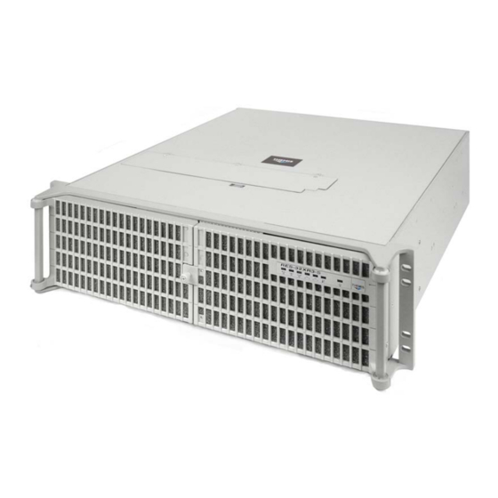
Preface This document, entitled RES-32XR3-S for X8DTL-6/6F Installation Manual, pro- vides instructions on how to install, configure, power up, and boot the Themis Rug- ged Enterprise Server RES-32XR3-S for X8DTL-6/6F (see Figure 1). Based on two 64-bit Quad-Core 5500-Series or Quad/Six-Core 5600-Series Xeon ®... -
Page 22: Table 1 Res-X2Xr3 20" Chassis Manual Matrix (Ac And Dc Power Supplies)
RES-32XR3-S for X8DTL-6/6F Installation Manual Table 1. RES-x2XR3 20” Chassis Manual Matrix (AC and DC Power Supplies) RES-32XR3 RES-22XR3 RES-12XR3 Manual Motherboard Manual Manual Manual Part Number Part Number Part Number X8DTH-iF Configuration 1 116790-024 1176789-024 X8DTH-6F X8DTi Configuration 2... -
Page 23: Table 2 Res-X2Xr3S / Res-X1Xr3 17" Chassis Manual Matrix (Ac And Dc Power Supplies)
T = Graphics chip; no sound chip w: Not applicable x: i = SATA only 3 = SAS 1.0 6 = SAS 2.0 y: LN4 = Extra gigabit Ethernet controller for two extra ports z: F = IPMI blank = No IPMI Themis Computer... -
Page 24: Table 3 Res-X2Xr3/Fio 16" Chassis Manual Matrix (Ac And Dc Power Supplies)
F = IPMI blank = No IPMI The 3RU-high (5.25”) RES-32XR3-S for X8DTL-6/6F has been designed to fit into a standard 19” rack and is provided with rack-mount brackets with handles. Optional rack-mount slides are also available. The RES-32XR3-S for X8DTL-6/6F is rugged... - Page 25 Preface tered DIMM memory modules. The RES-32XR3-S for X8DTL-6/6F is based on the functionality and capability of the following Intel chipset: • Intel 5500 (Tylersburg) chipset • ICH10R + IOH-24D An overview of RES-32XR3-S for X8DTL-6/6F design and specifications is given in Chapter 1, "Overview and Specifications", of this manual.
- Page 26 RES-32XR3-S for X8DTL-6/6F Installation Manual Caution: A caution describes a procedure or action that may result in damage to the equipment. This may involve—but is not restricted to—heavy equipment or sharp objects. To reduce the risk, follow the instructions accompanying this sym- bol.
-
Page 27: Overview And Specifications
1RES-32XR3-S for X8DTL-6/6F Overview and Specifications Overview The RES-32XR3-S for X8DTL-6/6F, (see Figure 1-1; a block diagram is given in Figure 1-2, page 1-3), is a rack-mounted system designed for above-average shock ® and vibration environments. The RES-32XR3-S supports dual Intel... -
Page 28: Table 1-2 Res-32Xr3-S Major Features
The RES-32XR3-S is designed within a 3RU-high (5.25”) form-factor 17” (43.2 cm) deep and 17” (43.2 cm) wide (which, with mounting brackets, fits a 19”-wide rack). Major features of the RES-32XR3-S for X8DTL-6/6F motherboard are listed in Table 1-2. -
Page 29: Figure 1-2 X8Dtl-6 Motherboard Block Diagram
SATA SATA#1 REAR USB #0/1 COM1 SATA#2 USB #2/3 SLB9635TT_1.2 Header W83527HG SATA#3 USB #4/5 Header COM2 (Optional for OEM) USB #6 SATA#4 Type A SATA#5 SATA#6 RJ45 VGA CONN PS2 KB/MS Figure 1-2. X8DTL-6 Motherboard Block Diagram Themis Computer... -
Page 30: Figure 1-3 External Features Of Res-32Xr3-S (Front And Rear)
PCI cards (graphics, RAID, NIC, etc.), two AC power supplies with latch locks and power-cord sockets, and all I/O connectors (see Figure 1-5 on page 1-7). Major internal components of the RES-32XR3-S for X8DTL-6/6F can be seen in Themis Computer... -
Page 31: System Leds And I/O Connectors
(cover removed) of Figure 1-4 on page 1-6. System LEDs and I/O Connectors All RES-32XR3-S system LEDs are located on the front panel (see A, Figure 1-5 on page 1-7); all I/O connectors are located on the rear panel (see B, Figure 1-5). - Page 32 (PCI-E 2.0 x4 in x8 slot) (PCI-E 2.0 x8 in x16 slot) Lithium Battery 120-mm Fan (1 of 2) CD/DVD Front Combo-Drive Storage Drive (1 of 8) Housing Figure 1-4. Major Components of RES-32XR3-S for X8DTL-6/6F (Open Top View) Themis Computer...
- Page 33 Rear Panel I/O Connectors IPMI Dedicated LAN PS/2 Mouse PS/2 Keyboard COM 1 Port VGA Port LAN 1 Port LAN 2 Port USB1 (top) Gigabit Ethernet USB0 (bottom) Figure 1-5. RES-32XR3-S for X8DTL-6/6F System LEDs and I/O Connectors Themis Computer...
-
Page 34: Table 1-3 System Leds
RES-32XR3-S for X8DTL-6/6F Installation Manual Table 1-3. System LEDs Symbol Description Power Indicates that the system is turned on. Storage Drive (HDD) Indicates SATA hard-drive activity. NIC1 (Gb Ethernet) Indicates network activity on LAN 1. ENET1 < > ENET2 NIC2 (Gb Ethernet) Indicates network activity on LAN 2. -
Page 35: Table 1-4 I/O Connectors
15-pin VGA connector to attach a monitor device. Standard RJ45 connectors to attach one or two gigabit Ethernet LAN Ethernet LAN Ports line(s)—LAN 1 and LAN 2. IPMI Dedicated LAN Port Standard RJ45 connector to attach a dedicated IPMI LAN line. (X8DTL-6F only) Themis Computer... -
Page 36: Chipset Overview
RES-32XR3-S for X8DTL-6/6F Installation Manual Chipset Overview Built upon the functionality and the capability of the 5500 platform, the RES- 32XR3-S for X8DTL-6/6F motherboard provides the performance and feature set required for dual-processor-based high-end systems optimized for HCP/Cluster sys- tems and intensive applications. The 5500 platform consists of the 5500 Series (LGA 1366) processor, the 5500 (IOH-24D), and the ICH10R (South Bridge). -
Page 37: Special Features
Setup section to change this setting. The default setting is Last State. PC Health Monitoring This section describes the PC health monitoring features of the RES-32XR3-S for X8DTL-6/6F motherboard. All have an onboard System Hardware Monitor chip that supports PC health monitoring. An onboard voltage monitor will scan these onboard voltages continuously: CPU0 Vcore, CPU1 Vcore, 1.5V, 5V, 5VSB, 12V, -12V,... -
Page 38: System Resource Alert
RES-32XR3-S for X8DTL-6/6F Installation Manual threshold. The overheat circuitry runs independently from the CPU. Once it detects that the CPU temperature is too high, it will automatically turn on the thermal fan control to prevent any overheat damage to the CPU. The onboard chassis thermal circuitry can monitor the overall system temperature and alert users when the chassis temperature is too high. -
Page 39: Main Switch Override Mechanism
The Super I/O provides functions that comply with ACPI (Advanced Configuration and Power Interface), which includes support of legacy and ACPI power manage- ment through an SMI or SCI function pin. It also features auto power management to reduce power consumption. 1-13 Themis Computer... -
Page 40: Overview Of The Winbond Wpcm450R Controller
The WPCM450 communicates with onboard components via six SMBus interfaces, fan control, and Platform Environment Control Interface (PECI) buses. Specifications 1.9.1 General Table 1-5 lists general specifications for the RES-32XR3-S. Table 1-5. RES-32XR3-S General Specifications Parameter Description Dimensions 5.25” (3RU) high 17”... - Page 41 Overview and Specifications Specifications Table 1-5. RES-32XR3-S General Specifications (Continued) Parameter Description Left and right rack-mount tabs attached to chassis 19” Rack-Mountable with Slide capability Left and right rack-mount slides are optional Temperature Operating: 0° up to 65° C (32° up to 149°F) Non-Operating: –40°...
-
Page 42: Electrical
= Not Applicable. 1.9.2.1 System Power The RES-32XR3-S operates with two N+1 redundant AC power supplies of 750- watts capacity each that auto-range single-phase AC input from 100 to 240 VAC (47 to 63 Hertz) sources. Filtered and fused (internal) AC is supplied to each power sup- ply from a rear-mounted power connection. -
Page 43: Output Voltage
1.9.3 Environmental 1.9.3.1 Shock The RES-32XR3-S for X8DTL-6/6F is designed to survive an elevated shock envi- ronment. All structural components are welded together, enabling the system to sur- vive a maximum 3-axis shock load of 35G at 25-ms duration. 1.9.3.2 Electrostatic Discharge The RES-32XR3-S for X8DTL-6/6F is designed to tolerate electrostatic pulses up to 15 kilovolts (KV) with no impact on system operation. - Page 44 Figure 1-6. RES-32XR3-S for X8DTL-6/6F with Front Sound Baffle Installed (Front View) Note: All RES systems are shipped with BIOS fan speed set to the quietest mode. The default fan speed control mode of the RES-32XR3-S for X8DTL-6/6F is En- ergy Saving/ES. 1-18...
- Page 45 Overview and Specifications Specifications Front Sound Baffle Figure 1-7. RES-32XR3-S for X8DTL-6/6F with Front Sound Baffle Installed (Front View) Front Access—Opening the two front doors of the RES-32XR3-S requires remov- ing the front sound baffle. To do this, loosen the two (2) captive knurled Phillips...
- Page 46 Rear Access—Accessing the I/O connectors and PCI card I/O on the rear of the RES-32XR3-S for X8DTL-6/6F requires opening the rear sound baffle door. To do this, loosen the four (4) captive knurled Phillips screws A holding the baffle door to the chassis (see A in Figure 1-8) and swing the door downward away from the chas- sis, exposing the rear connectors and PCI cards.
-
Page 47: Packaging And Shipping
AC power cords is 8.8 pounds (4 kg). The approximate weight of a RES-32XR3-S for X8DTL-6/6F (loaded with 2 CPUs, 6 DIMMs, 2 storage drives, 2 PCI cards, a CD-RW/DVD-ROM drive, and 2 power supplies) is approximately 26.5 pounds (12.0 kg). -
Page 48: Rack-Mount Slides (Optional)
1.10.2 Rack-Mount Slides (Optional) Rack-Mount Slides can be mounted on each side of the RES-32XR3-S for X8DTL- 6/6F for the purpose of sliding the unit in and out of a rack. Mounting slides are optional and can be ordered at the time of purchase. -
Page 49: Installation And Operation
• How to install a memory module, storage drive, PCI card, 120-mm-fan, power supply, and lithium battery. • Rack-mount brackets and slides • How to turn the RES-32XR3-S for X8DTL-6/6F on and off Installation Procedures Caution: Use industry-standard ESD grounding techniques when handling all components. - Page 50 1. Loosen the two captive Phillips screws holding the protective top access cover to the rear of the RES-32XR3-S for X8DTL-6/6F chassis (see A, Figure 2-1). 2. Both the front and sides of the cover have flat hooks or tabs underneath that fit under slots on the chassis top edges (see B, Figure 2-1).
-
Page 51: Memory Modules
4. Proceed to the appropriate section to install or replace a memory module (page 2-3), PCI card (page 2-7), or lithium battery (page 2-8). 2.1.2 Memory Modules The RES-32XR3-S for X8DTL-6/6F supports memory according to Table 2-1. Table 2-1. RES-32XR3-S for X8DTL-6/6F Memory Capacity Memory Parameters... -
Page 52: Installation
RES-32XR3-S for X8DTL-6/6F Installation Manual Table 2-4. Memory Population for 2CPUs Installed Memory Population for Optimal Performance -For a motherboard with Two CPUs installed CPU1 (To populate P1-DIMMs) CPU2 (To populate P2-DIMMs) Branch 0 Branch 1 Branch 2 Branch 0... -
Page 53: Figure 2-2 Remove The Air-Flow Deflector Screws
Installation and Operation Installation Procedures 4. If all the memory modules have been replaced in the system, replace the air flow diverter and secure it with the five screws previously removed. Figure 2-2. Remove the Air-Flow Deflector Screws Themis Computer... -
Page 54: Figure 2-3 Memory Module Slot Locations
RES-32XR3-S for X8DTL-6/6F Installation Manual Branch 0 P1 DIMM 1A Branch 1 P1 DIMM 2A Branch 2 P1 DIMM 3A Branch 0 P2 DIMM 1A Branch 1 P2 DIMM 2A Branch 2 P2 DIMM 3A Figure 2-3. Memory Module Slot Locations Press latch downward &... -
Page 55: Pci Cards
Installation and Operation Installation Procedures 2.1.3 PCI Cards RES-32XR3-S for X8DTL-6/6F supports six PCI/PCI-Express slots. (see Figure 2-5). Slot 1 Slot 1 PCI 33MHz Slot 2 PCI 33MHz Slot 3 PCI-E 1.0 x4 in x8 slot Slot 4 PCI-E 2.0 x4 in x8 slot Slot 5 PCI-E 2.0 x4 in x8 slot... -
Page 56: Lithium Battery
7. Attach any internal I/O cables to the installed PCI cards, and carefully fold and tuck any exposed ribbon cables into the cabinet. 8. If you have no further installations to perform, close the RES-32XR3-S for X8DTL-6/6F chassis by refastening the top cover removed in Section 2.1.1, “Remove Protective Top Cover,”... -
Page 57: Installing A Lithium Battery
2. Carefully press down on the battery until it clicks firmly into place. 2.1.5 SAS/SATA Storage Drive Perform the following steps to remove and install a SATA storage drive. The front doors of the RES-32XR3-S for X8DTL-6/6F must be unlocked and opened to Themis Computer... - Page 58 (SATA II ID0) is designated as the boot drive. 2.1.5.1 Opening the RES-32XR3-S for X8DTL-6/6F Front Doors The knurled captive screw on the front of the RES-32XR3-S for X8DTL-6/6F allows the doors to lock without a key. To unlock the doors, turn the screw counter- clockwise and pull both doors away from the chassis.
-
Page 59: Storage Drive Removal
Drive Release Drive Lock Button (one per drive) Figure 2-9. Unlocking the RES-32XR3-S for X8DTL-6/6F Storage Drives (Front Doors Removed) 2.1.5.2 Storage Drive Removal After opening the front doors, perform the following steps to remove and install a storage drive: 1. -
Page 60: Storage Drive Installation
3. Push the drive toward the rear (DO NOT CLOSE the latch handle while push- ing) until the drive is flush with the front of the chassis. The handle will swing closed when it comes into contact with the RES-32XR3-S for X8DTL-6/6F chassis. -
Page 61: Removing And Installing A 120-Mm Fan
Installation Procedures which can be “hot-swapped” in the field in the event of a fan failure. Note: Since RES-32XR3-S for X8DTL-6/6F fans are “hot-swappable”, it is not necessary to turn off system power in order to remove and replace a fan, 2.1.6.1 Removing and Installing a 120-mm Fan... -
Page 62: Power Supply
RES-32XR3-S for X8DTL-6/6F Installation Manual 2.1.7 Power Supply Each of the two load-sharing (N+1 redundant) power supplies can be hot-swapped while the system is still on and operational. 2.1.7.1 Removing a Power Supply Perform the following steps to remove a power supply:... -
Page 63: Power Supply
Extraction Handle Figure 2-12. The RES-32XR3-S for X8DTL-6/6F Power Supply Locking Mecha- nism 2. Put the right index finger on the power supply extraction handle and the right thumb on the left side of the power supply locking lever. -
Page 64: Installing A Power Supply
RES-32XR3-S for X8DTL-6/6F Installation Manual 3. Squeeze the locking lever toward the pull handle and firmly pull the power supply from the chassis. Caution: When pulling the power supply from the chassis, hold it at the bot- tom to prevent it from falling and damaging the unit. -
Page 65: Rack Mounts
The rack-mount brackets (flanges) are used to secure the chassis to the 19” rack (see Figure 2-13). Handles are used to pull the RES-32XR3-S for X8DTL-6/6F from the rack when rack-mount slides have been installed on the sides of the chassis (see fol- lowing section). -
Page 66: Operation
Operation 2.3.1 Plugging in the AC Power Cords Before powering on the RES-32XR3-S for X8DTL-6/6F, plug in the AC power cords as follows: 1. On the rear of the RES-32XR3-S for X8DTL-6/6F, plug an AC power cord (shipped with unit) into the AC power socket on each power supply (see Fig- ure 2-14). -
Page 67: Getting Started
Installation and Operation Operation 2. On the front of the RES-32XR3-S for X8DTL-6/6F push the system power on/off button (see Figure 2-15). This will cause the system POWER LED to light (green). Power LED System Power On/Off Button Figure 2-15. -
Page 68: Turning The System Off
1. To turn the RES-32XR3-S for X8DTL-6/6F power off, press and hold the sys- tem power on/off button (see Figure 2-15, page 2-16) for at least four (4) sec- onds. -
Page 69: Bios Setup Utility
BIOS Setup Utility Introduction This chapter describes the AMI BIOS Setup Utility for the RES-32XR3-S mother- board. The AMI ROM BIOS is stored in a Flash EEPROM and can be easily updated. This chapter describes the basic navigation of the AMI BIOS Setup Utility setup screen 3.1.1... -
Page 70: How To Change The Configuration Data
RES-32XR3-S for X8DTL-6/6F Installation Manual Note: The AMI BIOS has default text messages built in. Themis retains the op- tion to include, omit, or change any of these text messages. The AMI BIOS Setup Utility uses a key-based navigation system called “hot keys”. -
Page 71: Main Setup
<Enter>. Press the <Tab> key to move between fields. The date must be entered in Day MM/DD/YY format. The time is entered in HH:MM:SS format. Note: The time is in the 24-hour format. For example, 5:30 P.M. appears as 17:30:00. Themis Computer... -
Page 72: Supermicro X8Dtl-6 Motherboard
RES-32XR3-S for X8DTL-6/6F Installation Manual 3.2.2 Supermicro X8DTL-6 Motherboard • Version: This item displays the BIOS revision used in your system. • Build Date: This item displays the date when this BIOS was completed. 3.2.3 Processor The AMI BIOS will automatically display the status of the processor used in your system: •... -
Page 73: Advanced Setup Configurations
This option allows the bootup screen options to be modified between POST mes- sages or the OEM logo. Select Disabled to display the POST messages. Select Enabled to display the OEM logo instead of the normal POST messages. The options are Enabled and Disabled. Themis Computer... -
Page 74: Addon Rom Display Mode
RES-32XR3-S for X8DTL-6/6F Installation Manual 3.3.1.3 AddOn ROM Display Mode This sets the display mode for Option ROM. Select Keep Current to use the current AddOn ROM Display setting. Select Force BIOS to use the Option ROM display mode set by the system BIOS. The options are Force BIOS and Keep Current. -
Page 75: Interrupt 19 Capture
BIOS to monitor and attempt to reduce the level of Electromagnetic Interference caused by the components whenever needed. The options are Disabled and Enabled. 3.3.2.4 Hardware Prefetcher (Available when supported by the CPU) If set to Enabled, the hardware prefetcher will prefetch streams of data and instruc- Themis Computer... -
Page 76: Adjacent Cache Line Prefetch (Available When Supported By The Cpu)
RES-32XR3-S for X8DTL-6/6F Installation Manual tions from the main memory to the L2 cache to improve CPU performance. The options are Disabled and Enabled. 3.3.2.5 Adjacent Cache Line Prefetch (Available when supported by the CPU) The CPU fetches the cache line for 64 bytes if this option is set to Disabled. The CPU fetches both cache lines for 128 bytes as comprised if Enabled. -
Page 77: Simultaneous Multi-Threading (Available When Supported By The Cpu)
3.3.2.15 C-State Package Limit Setting (Available when Intel® C-State Tech is enabled) If set to Auto, the AMI BIOS will automatically set the limit on the C-State package register. The options are Auto, C1, C3, C6 and C7. Themis Computer... -
Page 78: C1 Auto Demotion (Available When The C-State Tech Is Enabled)
RES-32XR3-S for X8DTL-6/6F Installation Manual 3.3.2.16 C1 Auto Demotion (Available when the C-State Tech is en- abled) When enabled, the CPU will conditionally demote C3, C6 or C7 requests to C1 based on un-core auto-demote information. The options are Disabled and Enabled. -
Page 79: Qpi Links Speed
• Lockstep - The motherboard uses two areas of memory to run the same set of operations in parallel. 3.3.3.6 Demand Scrubbing A memory error-correction scheme where the Processor writes corrected data back into the memory block from where it was read by the Processor. The options are Enabled and Disabled. 3-11 Themis Computer... -
Page 80: Patrol Scrubbing
RES-32XR3-S for X8DTL-6/6F Installation Manual 3.3.3.7 Patrol Scrubbing A memory error-correction scheme that works in the background looking for and correcting resident errors. The options are Enabled and Disabled. 3.3.3.8 Channel Interleave/Bank Interleave This item allows the user to set memory interleave schemes for onboard memory channels or banks. -
Page 81: Intel Vt-D
The options are Enabled and Disabled and NUMA for SLES 11. 3.3.3.13 Intel I/OAT The Intel I/OAT (I/O Acceleration Technology) significantly reduces CPU overhead by leveraging CPU architectural improvements, freeing resources for other tasks. The options are Disabled and Enabled. 3-13 Themis Computer... -
Page 82: Active State Power Management
RES-32XR3-S for X8DTL-6/6F Installation Manual 3.3.3.14 Active State Power Management Select Enabled to start Active-State Power Management for signal transactions between L0 and L1 Links on the PCI Express Bus. This maximizes power-saving and transaction speed. The options are Enabled and Disabled. -
Page 83: Ide Detect Timeout (Sec)
Block Mode boosts the IDE drive performance by increasing the amount of data transferred. Only 512 bytes of data can be transferred per interrupt if Block Mode is not used. Block Mode allows transfers of up to 64 KB per interrupt. Select Disabled 3-15 Themis Computer... -
Page 84: Pio Mode
RES-32XR3-S for X8DTL-6/6F Installation Manual to allow data to be transferred from and to the device one sector at a time. Select Auto to allow data transfer from and to the device to occur multiple sectors at a time if the device supports it. The options are Auto and Disabled. -
Page 85: Pci/Pnp Configuration
The options are Disabled, Enabled, and Auto. 32-Bit Data Transfer Select Enable to enable the function of 32-bit IDE data transfer. The options are Enabled and Disabled. 3.3.5 PCI/PnP Configuration 3.3.5.1 Clear NVRAM 3-17 Themis Computer... -
Page 86: Plug & Play Os
RES-32XR3-S for X8DTL-6/6F Installation Manual This feature clears the NVRAM during system boot. The options are No and Yes. 3.3.5.2 Plug & Play OS Selecting Yes allows the OS to configure Plug & Play devices. (This is not required for system boot if your system has an OS that supports Plug & Play.) Select No to allow the AMI BIOS to configure all devices in the system. -
Page 87: Onboard Lan Option Rom Select
2F8/IRQ3, 3E8/IRQ4, 2E8/IRQ3 and 3F8/IRQ4. Serial Port 2 Attribute This feature allows the user to set the mode for Serial Port 2 as a normal serial port or a virtual COM port for Serial-Over-LAN (SOL). The options are SOL and. COM 3-19 Themis Computer... -
Page 88: Remote Access Configuration
RES-32XR3-S for X8DTL-6/6F Installation Manual 3.3.7 Remote Access Configuration 3.3.7.1 Remote Access This allows the user to enable the Remote Access feature. The options are Enabled and Disabled. If Remote Access is set to Enabled, the following items will display: 3.3.7.2 Serial Port Number... -
Page 89: Terminal Type
• The Early Alarm: Select this setting if you want the CPU overheat alarm (including the LED and the buzzer) to be triggered as soon as the CPU temper- ature reaches the CPU overheat threshold as predefined by the CPU manufac- turer. 3-21 Themis Computer... -
Page 90: Cpu 1 Temperature/Cpu 2 Temperature/System Temperature
RES-32XR3-S for X8DTL-6/6F Installation Manual • The Default Alarm: Select this setting if you want the CPU overheat alarm (including the LED and the buzzer) to be triggered when the CPU temperature reaches about 5 C above the threshold temperature as predefined by the CPU manufacturer to give the CPU and system fans additional time needed for CPU and system cooling. -
Page 91: System Temperature
The BL setting is recommended for regular sys- tems with normal hardware configurations. Select “Energy Saving/ES” for best 3-23 Themis Computer... -
Page 92: Voltage Readings
RES-32XR3-S for X8DTL-6/6F Installation Manual power efficiency and maximum quietness. The Options are: Full Speed/FS, Perfor- mance/PF, Balanced/BL, and Energy Saving/ES 3.3.8.3 Voltage Readings The following voltage readings will be displayed. CPU1 Vcore, CPU2 Vcore, 1.5V, 5V, 5VSB, 12V, -12V, 3.3Vcc, 3.3Vsb, and VBAT and Vtt. -
Page 93: Apic Acpi Sci Irq
The options are Set, Clear and Don't Change. TPM Owner Select Enable Install to set up a TPM ownership. Select Clear to void a TPM owner- ship. Select Disable Install to disable TPM ownership setup support. The options are 3-25 Themis Computer... -
Page 94: Ipmi Configuration
RES-32XR3-S for X8DTL-6/6F Installation Manual Don't Change, Enable Install, Disable Install and Clear. Execute TPM Command Select Enabled to allow the user to change executable TPM commands and TPM set- tings. Select Don't Change to keep the current TPM settings. The options are Don't Change, Enabled, and Disabled. -
Page 95: Clear Bmc System Event Log
[01]. Press “+” or “-” on your keyboard to change the Channel Number. 3.3.13.2 Channel Number Status This feature returns the channel status for the Channel Number selected above: Channel Number is “OK” or “Wrong Channel Number”. 3-27 Themis Computer... -
Page 96: Ip Address Source
RES-32XR3-S for X8DTL-6/6F Installation Manual 3.3.14 IP Address Source Select the source of this machine's IP address. If Static is selected, you will need to know and enter manually the IP address of this machine below. If DHCP is selected, the BIOS will search for a DHCP (Dynamic Host Configuration Protocol) server in the network it is attached to, and request the next available IP address. -
Page 97: Event Log Configuration
3.3.15.3 Clear event log This option clears the Event Log memory of all messages. The options are OK and Cancel. 3.3.15.4 PCIE Error Log Use this option to enable PCI error (PERR) logging. The options are Yes and No. 3-29 Themis Computer... -
Page 98: Security Settings
RES-32XR3-S for X8DTL-6/6F Installation Manual Security Settings The AMI BIOS provides a Supervisor and a User password. If you use both pass- words, the Supervisor password must be set first. Figure 3-3. Security Settings 3.4.1 Supervisor Password This item indicates if a Supervisor password has been entered for the system. “Not Installed”... -
Page 99: User Access Level (Available When Supervisor Password Is Set As Above)
Boot Sector Virus Protection When Enabled, the AMI BIOS displays a warning when any program (or virus) issues a Format command or attempts to write to the boot sector of the storage drive. The options are Enabled and Disabled. 3-31 Themis Computer... -
Page 100: Boot Configuration
RES-32XR3-S for X8DTL-6/6F Installation Manual Boot Configuration Figure 3-4. Boot Settings Use this feature to configure boot settings. 3.5.1 Boot Device Priority This feature allows the user to specify the sequence of priority for the Boot Device. The settings are 1st boot device, 2nd boot device, 3rd boot device, 4th boot device, 5th boot device and Disabled. -
Page 101: Removable Drives
This feature allows the user to specify the boot sequence from available CD/DVD Drives. 3.5.5 Retry Boot Devices If this feature is enabled, the system will continue to search for the next boot device if the current boot device is not available. The options are Enabled and Disabled. 3-33 Themis Computer... -
Page 102: Exit Options
RES-32XR3-S for X8DTL-6/6F Installation Manual Exit Options Select the Exit tab from the AMI BIOS Setup Utility screen to enter the Exit Setup screen. Figure 3-5. Exit Options 3.6.1 Save Changes and Exit After configuring the Setup settings, select this option to save the changes and exit the BIOS Setup Utility and reboot the computer, so the new system configuration parameters can take effect. -
Page 103: Discard Changes
Flashing the wrong BIOS can cause irreparable damage to the system. In no event shall Themis be liable for direct, indirect, special, incidental, or consequential dam- ages arising from a BIOS update. If you need to update the BIOS, do not shut down or reset the system while the BIOS is updating. -
Page 104: Boot Sector Recovery From A Usb Device
RES-32XR3-S for X8DTL-6/6F Installation Manual 3.7.1 Boot Sector Recovery from a USB Device This feature allows the user to recover a BIOS image using a USB device without additional utilities needed. A user can download the BIOS image into a USB flash device, and name the file “SUPER.ROM”... - Page 105 5. Follow the instructions given on the screen to update the BIOS. These instruc- tions are also shown below. a. At the prompt, press the <SpaceBar> to update the BIOS. b. When asked to confirm BIOS updating, press <y> to confirm BIOS up- dates. 3-37 Themis Computer...
-
Page 106: Figure 3-6 Ami_Flsh Hyperterminal
RES-32XR3-S for X8DTL-6/6F Installation Manual c. Press <y> again to begin flashing BIOS remotely. Note: Be sure to complete Steps a to c above quickly because you have a second or less to do so. 6. Once you've completed the instructions given, a screen will display to indicate that remote flashing is starting and the new BIOS file is being uploaded. -
Page 107: Figure 3-7 Rom File Extraction
VT-100 and XModem protocols, including protocols designed for GNU/LINUX & BSD operating systems such as minicom. It is recommended that the terminal program be configured to use the 'CR/LF' style of line termina- tion. 3-39 Themis Computer... -
Page 108: Bios Error Beep Codes
RES-32XR3-S for X8DTL-6/6F Installation Manual BIOS Error Beep Codes During the POST (Power-On Self-Test) routines, which are performed each time the system is powered on, errors may occur. Non-fatal errors are those which, in most cases, allow the system to continue the boot-up process. -
Page 109: Appendix A. Connector Pinouts
I/O panel of the RES-32XR3-S for X8DTL-6/6F. PS/2 Keyboard and Mouse The RES-32XR3-S provides a 6-pin female mini-DIN connector for the PS/2 key- board, and another for the PS/2 mouse. Signals for both connectors are defined in Table A-1. -
Page 110: Usb Ports
RES-32XR3-S for X8DTL-6/6F Installation Manual USB Ports The RES-32XR3-S supports two USB port connectors (see Figure A-1 for a connec- tor pinout), USB 0 and USB 1, on the rear I/O panel. An additional onboard USB port (USB 2) and 2 USB internal headers can be accessed directly from the mother- board. -
Page 111: Vga Display Port
VGA Display Port VGA Display Port The RES-32XR3-S supports a single 15-pin (three 5-pin rows) female VGA graph- ics display port connector on the rear I/O panel (see Figure A-3 for a connector pinout). Pinout signal descriptions are listed in Table A-4... -
Page 112: Gigabit Ethernet Lan Ports
The right LED, when lit, indicates LAN activity (network traffic). IPMI Dedicated LAN Port (X8DTL-6F Only) The single IPMI dedicated Ethernet LAN port on the RES-32XR3-S rear I/O panel has identical pinout and signal descriptions as the LAN 1 and LAN 2 Ethernet ports described in the previous Section A.5, “Gigabit Ethernet LAN Ports”. -
Page 113: Appendix B. Rack-Mount Slide Installation
An optional set of two rack-mount slides (left side and right side) is available for all RES-32 systems, and should be ordered at the time of purchase. The RES-32XR3-S for X8DTL-6/6F chassis contains five threaded screw holes on each side to accom- modate #8-32 size screws (included with the rack-mount slide kit);... - Page 114 Two rear (long) slide brackets e. Assorted screws, washers, and nuts Follow these steps to install a steel rack-mount slide to the RES-32XR3-S for X8DTL-6/6F chassis: 1. Attach the inside slide section (see Figure B-2 on page B-3) to both sides of the RES-32XR3-S for X8DTL-6/6F chassis using four #8-32 screws per side.
- Page 115 (included in slide kit) Attach both inside slide sections to the left and right sides of the RES-32XR3-S chassis with #8-32 screws (included in slide kit) Figure B-1. RES-32XR3-S for X8DTL-6/6F Rack-Mount Slide Installation...
- Page 116 RES-32XR3-S for X8DTL-6/6F Installation Manual Themis Computer...
-
Page 117: Appendix C. Red Hat Enterprise Linux 5 Installation
Welcome to the Red Hat ® Enterprise Linux ® Installation Guide. This guide contains useful information to assist you during the installation of Red Hat Enterprise Linux via DVD device, from fundamental concepts such as installation preparation to the step-by-step installation procedure. Themis Computer... -
Page 118: Installation
RES-32XR3-S for X8DTL-6/6F Installation Manual Installation C.2.1 Step 1. Figure C-1. Power On after Linux DVD is Inserted into Drive Step 1: Insert the Redhat Enterprise Linux 5 DVD and Power on the system; you will see the first installation screen with a boot prompt, press “ENTER” to begin installation (see Figure C-1 on page C-2). -
Page 119: Figure C-3 Welcome Screen
The installation program tries to define the appropriate time zone based on what you specify on this screen. Once you have made the language selection, click Next to continue. (see Figure C-4 on page C-3) Themis Computer... -
Page 120: Figure C-5 Selecting Layout Type
RES-32XR3-S for X8DTL-6/6F Installation Manual C.2.5 Step 5 Figure C-5. Selecting Layout Type Step 5: Using your mouse, select the correct layout type (for example, U.S. English) for the keyboard you would prefer to use for the installation and as the sys- tem default. -
Page 121: Figure C-7 Partitioning
You can configure an iSCSI target for installation, or disable a dmraid device from this screen by clicking on the 'Advanced storage configuration' button (see Figure C-7 on page C-5). Click Next to continue. Themis Computer... -
Page 122: Figure C-8 Reviewing Option
RES-32XR3-S for X8DTL-6/6F Installation Manual C.2.8 Step 8 Figure C-8. Reviewing Option Step 8: Create default layout allows you to have some control concerning what data is removed (if any) from your system. Your options are: • Remove all partitions on selected drives and create default layout — select this option to remove all partitions on your hard drive(s) (this includes partitions created by other operating systems such as Windows VFAT or NTFS partitions). -
Page 123: Figure C-9 Creating A Custom Layout
Red Hat Enterprise Linux. This is done by defining mount points for one or more partitions in which Red Hat Enterprise Linux is installed. You may also need to create and/or delete partitions at this time (see Figure C-9 on page C-7). Click Next. Themis Computer... -
Page 124: Figure C-10 Setting Up Boot Loader
RES-32XR3-S for X8DTL-6/6F Installation Manual C.2.10 Step 10 Figure C-10. Setting Up Boot Loader Step 10: Once you have configured your partitions, set up a boot loader. If you select “No Boot Loader will be Installed,” you’ll need to use a third-party boot loader such as Partition Magic or Microsoft’s TLDR. -
Page 125: Figure C-11 Master Boot Record (Mbr
In this case, your other boot loader takes control first. You can then configure that boot loader to start GRUB, which then boots Red Hat Enterprise Linux. If your system only uses Red Hat Enterprise Linux, you should choose the MBR. Themis Computer... -
Page 126: Figure C-12 Network Devices List
RES-32XR3-S for X8DTL-6/6F Installation Manual Click the Change Drive Order button if you would like to rearrange the drive order or if your BIOS does not return the correct drive order. Changing the drive order may be useful if you have multiple SCSI adapters, or both SCSI and IDE adapters, and you want to boot from the SCSI device. -
Page 127: Figure C-13 Edit Interface Pop-Up Screen
If you select Activate on boot, your network interface is started when you boot (see Figure C-13 on page C-11). If you do not have DHCP client access or you are unsure what to provide here, please contact your network administrator. Click OK. C-11 Themis Computer... -
Page 128: Figure C-14 Selecting Time Zone
RES-32XR3-S for X8DTL-6/6F Installation Manual C.2.14 Step 14 Figure C-14. Selecting Time Zone Step 14: Set your time zone by selecting the city closest to your computer's physical location. Click on the map to zoom in to a particular geographical region of the world (see Figure C-14 on page C-12). -
Page 129: Figure C-15 Setting Up Root Account And Password
Your root account is similar to the administrator account used on Windows NT machines. The root account is used to install packages, upgrade RPMs, and perform most system maintenance. Logging in as root gives you complete control over your system (see Figure C-15 on page C-13). Click Next. C-13 Themis Computer... -
Page 130: Figure C-16 Package Installation Default Screen
RES-32XR3-S for X8DTL-6/6F Installation Manual C.2.16 Step 16 Figure C-16. Package Installation Default Screen Now that you have made most of the choices for your installation, you are Step 16: ready to confirm the default package selection or customize packages for your sys- tem. -
Page 131: Figure C-17 Optional Packages
Optional packages to view which packages are installed by default, and to add or remove optional packages from that group (see Figure C-17 on page C-15). If there are no optional components this button will be disabled. Click Next. C-15 Themis Computer... - Page 132 RES-32XR3-S for X8DTL-6/6F Installation Manual C.2.18 Step 18 Figure C-18. Option to Review or Continue Step 18: Once you have selected the package groups of your choice, you get one last chance to go back before starting the installation process. Click Next if you’re happy with your choices, or click Back to make changes (see Figure C-18 on page C-16).
- Page 133 • Do nothing — after the boot loader's time-out period, (by default, five seconds) the boot loader automatically boots the default boot entry. Do whatever is appropriate to boot Red Hat Enterprise Linux. One or more screens of messages should scroll by. C-17 Themis Computer...
- Page 134 RES-32XR3-S for X8DTL-6/6F Installation Manual C.2.21 Step 21 Figure C-21. Login Screen Eventually, a prompt or a GUI login screen appears (if you installed Step 21: login: the X Window System and chose to start X automatically). (see Figure C-21 on page C-18).
-
Page 135: Appendix D. Optional Remote On/Off Switch
Remote On/Off Configuration Customers interested in installing an optional switch from which to remotely turn the RES-32XR3-S for X8DTL-6/6F on or off are able to order a Remote On/Off Switch module that is easily installed in an available storage-drive bay (see Figure D-1, which shows the Remote On/Off Switch installed in an RES-32XR3/FIO sys- tem). -
Page 136: Remote On-Only Configuration
RES-32XR3-S for X8DTL-6/6F is turned OFF, pressing the remote switch ON will turn the system on. Turning the RES system off, however, requires pressing the ON/ OFF button that is located directly on the front of the RES-32XR3-S for X8DTL-6/ 6F chassis. -
Page 137: Appendix E. Re-Packing Instructions
Re-Packing Instructions Re-Packaging for Shipment If it becomes necessary to return equipment to Themis Computer, it is very impor- tant that the equipment be shipped in packaging that provides adequate protection against crushing and moisture invasion. The original packaging is best for this pur- pose, provided the packaging is retained in serviceable condition. -
Page 138: Instructions For Re-Packing
RES-32XR3-S for X8DTL-6/6F Installation Manual side with the plastic membrane is against the equipment. Top Layer Membrane Bottom Layer Packing Container Figure E-1. Packaging Components Instructions for Re-Packing Re-assemble the packing material about the equipment in accordance with the fol- lowing instructions: (See Figure E-2. - Page 139 • Seal the top of the box with strong packing tape, wrapping the tape completely around the box, both lengthwise, and crosswise. • Prepare for shipment in accordance with the instructions received from Themis Computer. Figure E-2.
- Page 140 RES-32XR3-S for X8DTL-6/6F Installation Manual Themis Computer...
- Page 141 2-1 Configuration One Table Chipset 1-2 Memory 1-2 Processors 1-2 I/O Connectors Configuration, system 2-17 Ethernet LAN Port 1-9 CPU 1-1 PS/2 keyboard 1-9 PS/2 mouse 1-9 Serial Ports 1-9 USB Serial Ports 1-9 Dimensions, chassis 1-2 Index-1 Themis Computer...
- Page 142 I/O faceplates 1-4 Notes xxi ICH1OR + IOH-24D xxi Installation procedures 2-1 installing rack-mount slides B-1 Opening the RES-32XR3-S Front Doors 2-9 memory modules 2-4 Operating temperature 1-2 PCI cards 2-7 Optional Remote On/Off Switch D-1 Instructions for Re-Packing E-2...
- Page 143 Re-Packaging for Shipment E-1 Packaging and Shipping 1-21 Re-Packing Instructions E-1 Plug Type 1-16 RES-32XR3-S 1-1 Power Factor 1-16 RES-32XR3-S General Specifications 1-14 Relative Humidity 1-15 RES-32XR3-S Major Features 1-2 Shock 1-17 reset switch 1-4 Temperature 1-15 RES-x2XR3 17" Manual Matrix (AC and DC...
- Page 144 RES-32XR3-S for X8DTL-6/6F Installation Manual X8DTL-6F Motherboard Block Diagram 1-3 Xeon processors 1-1 Index-4 Themis Computer...
- Page 145 Place Stamp Here Themis Computer 47200 Bayside Parkway Fremont, CA 94538 Attn: Publications Department Fold here; tape at top to seal...
- Page 146 Reader Comment Card We welcome your comments and suggestions to help improve the RES-32XR3-S for X8DTL-6/-6F Installation Manual. Please take time to let us know what you think about this manual. • Information provided in the manual was complete. Agree___...
Need help?
Do you have a question about the RES-32XR3-S and is the answer not in the manual?
Questions and answers