
Related Manuals for Themis RES-32XR3/FIO


Summary of Contents for Themis RES-32XR3/FIO
- Page 1 User M anual User M anual I nstallation I nstallation M anual M anual 3RU 19” Rack-Mount Rugged Enterprise Server with X8DAH+-F Motherboard Configuration / Two Quad-Core 5500 or Quad/Six-Core 5600 Xeon CPUs...
- Page 3 RES-32XR3/FIO Installation Manual* Version 1.0— July 2010 * SuperMicro Motherboard X8DAH+-F Themis Computer—Americas and Pacific Rim Themis Computer—Rest of World 47200 Bayside Parkway 5 Rue Irene Joliot-Curie Fremont, CA 94538 38320 Eybens, France Phone (510) 252-0870 Phone +33 476 14 77 80...
-
Page 4: Safety Precautions
Themis Computer assumes no responsibility for inaccuracies. Themis Computer retains the right to make changes to this publication at any time without prior notice. Themis Computer does not assume any liability arising from the application or use of this publication or the product(s) described herein. - Page 5 RES-32XR3/FIO Installation Manual Version Revision History Version 1.0 ....................July 2010 Themis Computer...
-
Page 6: Safety Instructions
In these cases, the device must be shut down and secured against unintentional operation. • Repairs may only be carried out by a person authorized by Themis Computer. • The device may only be opened for the installation and removal of extension... -
Page 7: Grounding Methods
RES-32XR3/FIO Installation Manual and the lithium battery—all in accordance with the instructions given in this manual. • If extensions are made to the device, the legal stipulations and the device spec- ifications must be observed. • The device must be switched off when removing the top cover; for example, before installing extension (PCI) cards. - Page 8 RES-32XR3/FIO Installation Manual 2. Use anti-static mats, heel straps, or air ionizers to give added protection. 3. Handle electrostatic-sensitive components, boards, and assemblies by the case or the PCB edge. 4. Avoid contact with pins, leads, or circuitry. 5. Turn off power and input signals before inserting and removing connectors or test equipment.
-
Page 9: Table Of Contents
1.10.2.2 Output Voltage ................1-17 1.10.3 Environmental ..................1-17 1.10.3.1 Shock ..................1-17 1.10.3.2 Electrostatic Discharge ............. 1-17 1.11 Packaging and Shipping ..................1-18 1.11.1 Accessory Kit ................... 1-18 1.11.2 Rack-Mount Slides (Optional) ..............1-19 2. Installation and Operation ................... 2-1 Themis Computer... - Page 10 RES-32XR3/FIO Installation Manual 2.1 Installation Procedures ................... 2-1 2.1.1 Remove Protective Top Cover ..............2-1 2.1.2 Memory Modules ..................2-3 2.1.2.1 Installation .................. 2-4 2.1.3 PCI Cards ....................2-7 2.1.3.1 Installing Cards ................2-7 2.1.4 Lithium Battery ..................2-8 2.1.4.1 Removing the Lithium Battery ........... 2-8 2.1.4.2 Installing a Lithium Battery ............
- Page 11 (Available when Intel® C-State Tech is enabled) ...... 3-9 3.3.2.14 C1 Auto Demotion ..............3-9 3.3.2.15 C3 Auto Demotion ..............3-9 3.3.3 DCA Technology ..................3-9 3.3.3.1 DCA Prefetch Delay ..............3-9 3.3.4 Advanced Chipset Control ............... 3-10 3.3.4.1 QPI Links Speed ............... 3-10 Themis Computer...
- Page 12 RES-32XR3/FIO Installation Manual 3.3.4.2 QPI Frequency ................3-10 3.3.4.3 QPI L0s and L1 ................. 3-10 3.3.4.4 Memory Frequency ..............3-10 3.3.4.5 Memory Mode ................3-10 3.3.4.6 Demand Scrubbing ..............3-11 3.3.4.7 Patrol Scrubbing ............... 3-11 3.3.4.8 Throttling - Closed Loop / Throttling - Open Loop ....3-11 3.3.4.9 HDA Controller ................
- Page 13 3.3.14.1 Channel Number ............... 3-27 3.3.14.2 Channel Number Status ............3-27 3.3.15 IP Address Source ..................3-27 3.3.16 Mac Address .................... 3-27 3.3.17 SET PEF Configuration ................3-28 3.3.17.1 PEF Support ................3-28 3.3.17.2 BMC Watch Dog Timer Action ..........3-28 Themis Computer...
- Page 14 RES-32XR3/FIO Installation Manual 3.3.18 Event Log Configuration ................. 3-29 3.3.18.1 View Event Log ................ 3-29 3.3.18.2 Mark all events as read ............. 3-29 3.3.18.3 Clear event log ................3-29 3.3.18.4 PCI Error Log ................3-29 3.4 Security Settings ....................3-30 3.4.1 Supervisor Password ................
- Page 15 C.2.17 Step 17 ....................C-15 C.2.18 Step 18 ....................C-16 C.2.19 Step 19 ....................C-16 C.2.20 Step 20 .....................C-17 C.2.21 .Step 21 ....................C-18 C.2.22 Step 22 ....................C-18 Appendix D. Optional Remote On/Off Switch .............. D-1 D.1 Remote On/Off Configuration ................D-1 xiii Themis Computer...
- Page 16 RES-32XR3/FIO Installation Manual D.2 Remote Only Configuration .................. D-2 D.3 Ordering the Remote On/Off Switch ..............D-2 Appendix E. Re-Packing Instructions ................E-1 E.1 Re-Packaging for Shipment ...................E-1 E.2 Packing Components .....................E-1 E.3 Instructions for Re-Packing ...................E-2 Index ........................ Index-1 Reader Comment Card...
- Page 17 Right Rack-Mount Bracket ................2-14 Figure 2-13 AC Power Socket and LED on the RES-32XR3/FIO........2-15 Figure 2-14 System Power Button and LED on the RES-32XR3/FIO Front....2-16 Figure 3-1 Main BIOS Setup Screen ................. 3-3 Figure 3-2 Advanced Settings ................... 3-5 Figure 3-3 Security Settings ....................
- Page 18 Figure A-1 USB Connector Pinout..................A-2 Figure A-2 COM 1 Serial Connector Pinout ..............A-2 Figure A-3 RES-32XR3/FIO VGA Connector Pinout ............A-3 Figure A-4 Ethernet Connector, Type RJ45..............A-4 Figure B-1 Screw Locations for Rack-Mount Slides ............B-1 Figure B-2 RES-32XR3/FIO Rack-Mount Slide Installation ..........
- Page 19 Approximate Weights of the RES Series............1-19 Table 2-1 RES-32XR3/FIO Memory Capacity............... 2-3 Table 2-2 RES-32XR3/FIO Optimal Memory Population—Two CPUs Installed ..2-3 Table A-1 PS/2 Keyboard/Mouse Pinout and Signal Descriptions ........ A-1 Table A-2 USB Connector Pinout Signal Descriptions ..........A-2 Table A-3 COM 1 Serial Connector Pinout Signal Descriptions ........
- Page 20 RES-32XR3/FIO Installation Manual xviii Themis Computer...
-
Page 21: Preface
Preface This document, entitled RES-32XR3/FIO Installation Manual, provides instructions on how to install, configure, power up, boot, and perform diagnostics on the Themis Rugged Enterprise Server RES-32XR3/FIO (see photo), based on two 64-bit Intel 5520 Series Xeon Quad/Dual-Core CPUs with up to 6.4 GT/s each. -
Page 22: Table 1 Res-X2Xr3 Manual Matrix (Ac And Dc Power Supplies)
RES-32XR3/FIO Installation Manual Table 1. RES-x2XR3 Manual Matrix (AC and DC Power Supplies) RES-32XR3 RES-22XR3 RES-12XR3 Manual Motherboard Manual Manual Manual Part Number Part Number Part Number X8DTH-iF Configuration 1 116790-024 1176789-024 X8DTH-6F X8DTi Configuration 2 X8DTi-F 117022-024 117017-024 X8DTi-LN4F... -
Page 23: Table 2 Res-X2Xr3S / Res-X1Xr3 17" Chassis Manual Matrix (Ac And Dc Power Supplies)
T = Graphics chip; no sound chip w: Not applicable x: i = SATA only 3 = SAS 1.0 6 = SAS 2.0 y: LN4 = Extra gigabit Ethernet controller for two extra ports z: F = IPMI blank = No IPMI Themis Computer... -
Page 24: Table 3 Res-X2Xr3/Fio 16" Chassis Manual Matrix (Ac And Dc Power Supplies)
F = IPMI blank = No IPMI The 3RU-high (5.25”) RES-32XR3/FIO has been designed to fit into a standard 19” rack and is provided with rack-mount brackets with handles. Optional rack-mount slides are also available. The RES-32XR3/FIO is rugged enough to withstand extreme shock (up to 35G), temperature, and EMI as that associated with such demanding markets as the military, aerospace, and telecommunications industries. - Page 25 This manual is intended for an experienced system administrator with a knowledge of both networking and high-speed server systems. Website Information Themis Computer corporate and product information may be accessed on the World Wide Web by browsing the website http://www.themis.com. Your Comments are Welcome We are interested in improving our documentation and welcome your comments and suggestions.
- Page 26 RES-32XR3/FIO Installation Manual Caution: A caution describes a procedure or action that may result in damage to the equipment. This may involve—but is not restricted to—heavy equipment or sharp objects. To reduce the risk, follow the instructions accompanying this sym- bol.
-
Page 27: Overview And Specifications
Section Chapter 1RES-32XR3/FIO Overview and Specifications Overview The RES-32XR3/FIO, (see Figure 1-1 below), is a rack-mounted system designed for above-average shock and vibration environments. The RES-32XR3/FIO supports ® single or dual Intel 1366-pin LGA Xeon 64-bit processors (each up to 2.33 GHz... -
Page 28: Table 1-1 Res-32Xr3/Fio Motherboard Options
The RES-32XR3/FIO is designed within a 3RU-high (5.25”) form-factor 16” (40.6 cm) deep and 17.07” (43.4 cm) wide (which, with mounting brackets, fits a 19”-wide rack). Major features of the RES-32XR3/FIO motherboard are listed in Table 1-2. Table 1-2. RES-32XR3/FIO Major Features Processors •... -
Page 29: Figure 1-2 X8Dah+-F Motherboard Block Diagram
Overview and Specifications Overview Figure 1-2. X8DAH+-F Motherboard Block Diagram Themis Computer... -
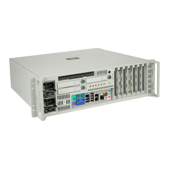
Page 30: Figure 1-3 External Features Of Res-32Xr3/Fio (Front)
RAID, NIC, etc.), two AC power supplies with latch locks and power-cord sockets, and all I/O connectors (see Figure 1-5 on page 1-7). Major features of the RES-32XR3/FIO are described in Table 1-3. Major internal components can be seen in the open top view (cover removed) of Figure 1-4 on page 1-6. -
Page 31: System Leds And I/O Connectors
System LEDs and I/O Connectors All RES-32XR3/FIO system LEDs and all I/O connectors are located on the front panel (see A, Figure 1-5, page 1-7). LEDs are described in Table 1-4 on page 1-8; I/O connectors are described in Table 1-5, page 1-9. -
Page 32: Figure 1-4 Major Components Of Res-32Xr3/Fio (Open Top View)
Combo-Drive Housing (PCI-E 2.0 x8 in x16 slot) (PCI-E x4 in an x8 slot) (PCI-Express 2.0 x16) (PCI-Express 2.0 x8) Lithium Battery (under cabling) 120-mm Fan (1 of 3) Figure 1-4. Major Components of RES-32XR3/FIO (Open Top View) Themis Computer... -
Page 33: Figure 1-5 Res-32Xr3/Fio System Leds And I/O Connectors1
(PS1) (PS2) IPMI Dedicated LAN Knockout slot COM 1 Port Back-surround CEN/LFE LAN2 Line-in PS2 Mouse PS2 Keyboard Front VGA Port USB0 (top) Microphone-in LAN1 USB 2-5 USB1 (btm) Side-surround Figure 1-5. RES-32XR3/FIO System LEDs and I/O Connectors1 Themis Computer... -
Page 34: Table 1-4 System Leds
RES-32XR3/FIO Installation Manual Table 1-4. System LEDs Symbol Description Power Indicates that the system is turned on. Storage Drive (SD) Indicates SATA storage drive activity. NIC1 (Gb Ethernet) Indicates network activity on LAN 1. ENET1 < > ENET2 NIC2 (Gb Ethernet) Indicates network activity on LAN 2. -
Page 35: Table 1-5 I/O Connectors
15-pin VGA connector to attach a monitor device. Standard RJ45 connectors to attach one or two gigabit Ethernet LAN Ethernet LAN Ports line(s)—LAN 1 and LAN 2. IPMI Dedicated LAN Standard RJ45 connector to attach a dedicated IPMI LAN line. Port Themis Computer... -
Page 36: Chipset Overview
Chipset Overview Built upon the functionality and capability of the Intel 5500/5600 series processor platform, the RES-32XR3/FIO motherboard provides the performance and feature sets required for dual-processor/IOH-based high-end systems optimized for High Performance Computing (HPC)/Cluster platforms. The 5520 chipset consists of the IOH 36D (I/O Hub), and the ICH10R (South Bridge). -
Page 37: Special Features
Setup section to change this setting. The default setting is Last State. PC Health Monitoring This section describes the PC health monitoring features of the RES-32XR3/FIO motherboard. All have an onboard System Hardware Monitor chip that supports PC health monitoring. An onboard voltage monitor will scan these onboard voltages... -
Page 38: Cpu Fan Auto-Off In Sleep Mode
RES-32XR3/FIO Installation Manual circuitry can monitor the overall system temperature and alert users when the chassis temperature is too high. Caution: To avoid possible system overheating, please be sure to provide adequate airflow to your system. 1.5.3 CPU Fan Auto-Off in Sleep Mode The CPU fan becomes active when the power is turned on. -
Page 39: Slow Blinking Led For Suspend-State Indicator
It is even more important for processors that have high CPU clock rates. The RES-32XR3/FIO motherboard can accommodate 24-pin ATX power supplies. Although most power supplies generally meet the specifications required by the CPU, some are inadequate. In addition, the 12V 8-pin power connections are also required to ensure adequate power supply to the system. -
Page 40: Super I/O
RES-32XR3/FIO Installation Manual filter to shield the computer from noise. It is recommended that you also install a power surge protector to help avoid problems caused by power surges. Super I/O The disk drive adapter functions of the Super I/O chip include a floppy disk drive... -
Page 41: Specifications
Overview and Specifications Specifications 1.10 Specifications 1.10.1 General Table 1-6 lists general specifications for the RES-32XR3/FIO. Table 1-6. RES-32XR3/FIO General Specifications Parameter Description 5.25” (3RU) high Dimensions 17.07” (43.4 cm) wide (19” rack-mountable) 16” (40.6 cm) deep (including clearance for the rear thumb... -
Page 42: Electrical
= Not Applicable. 1.10.2.1 System Power The RES-32XR3/FIO operates with two N+1 redundant AC power supplies of 750- watts capacity each that auto-range single-phase AC input from 100 to 240 VAC (47 to 63 Hertz) sources. Filtered and fused (internal) AC is supplied to each power sup- ply from a front-mounted power connection. -
Page 43: Output Voltage
3-axis shock load of 35G at 25-ms duration. 1.10.3.2 Electrostatic Discharge The RES-32XR3/FIO is designed to tolerate electrostatic pulses up to 15 kilovolts (KV) with no impact on system operation. 1-17... -
Page 44: Packaging And Shipping
C. Two Storage Drive Barrel Keys When you unpack the RES-32XR3/FIO, please verify that all of these items are included. If any of these items are missing or not as pictured, please call Themis Technical Support at 510-252-0870, or send an email to support@themis.com. -
Page 45: Rack-Mount Slides (Optional)
1.11.2 Rack-Mount Slides (Optional) Rack-Mount Slides can be mounted on each side of the RES-32XR3/FIO for the pur- pose of sliding the unit in and out of a rack. Mounting slides are optional and can be ordered at the time of purchase. - Page 46 RES-32XR3/FIO Installation Manual 1-20 Themis Computer...
-
Page 47: Installation And Operation
To install or replace a storage drive, fan, or power supply, skip the next section and proceed directly to page 2-9, page 2-11, or page 2-12, respectively. Replacement of motherboard components requires removal of the protective cover. 2.1.1 Remove Protective Top Cover To access a motherboard component, open the RES-32XR3/FIO as follows: Themis Computer... -
Page 48: Figure 2-1 Remove The Res-32Xr3/Fio Protective Access Cover
1. Loosen the four captive Phillips screws holding the protective top access cover to the rear of the RES-32XR3/FIO chassis (see A, Figure 2-1). 2. Both the front and sides of the cover have flat hooks or tabs underneath that fit under slots on the chassis top edges (see B, Figure 2-1). -
Page 49: Memory Modules
Installation and Operation Installation Procedures 2.1.2 Memory Modules The RES-32XR3/FIO supports memory according to Table 2-1. Table 2-1. RES-32XR3/FIO Memory Capacity Memory Parameters DDR3 Motherboard Number Pins per Capacity Registered Speed (MHz) of DIMMS DIMM X8DAH+-F 144 GB 1333/1066/800 Caution: Exercise extreme caution when installing or removing FBD Memory Modules to prevent any possible damage. -
Page 50: Installation
RES-32XR3/FIO Installation Manual 2.1.2.1 Installation The following procedure explains how to install the DDR3 Memory Modules. 1. Loosen and remove the screws securing the air-flow deflector and PCI card retainer bracket in the following manner: (see Figure 2-2). • Screw A—Unscrew the captive screw marked “A” from it’s socket, remove the PCI card retainer bracket and store it in a safe place. -
Page 51: Figure 2-3 Memory Module Slot Locations
(see Figure 2-4 on page 2-6), then pulling the old module directly up from the slot until it is free of the connector (see Figure 2-4 on page 2-6). Themis Computer... - Page 52 RES-32XR3/FIO Installation Manual Press latch downward & outward at each end Figure 2-4. Memory Module Removal 3. Before inserting a new memory module into the vacant slot, make sure that the two latches are pulled outward away from the center of the slot.
-
Page 53: Pci Cards
Installation and Operation Installation Procedures 2.1.3 PCI Cards The RES-32XR3/FIO supports seven PCI-Express slots. (see Figure 2-5). Slot 1 Slots 1, 3, 5 and 7 are PCI-Express 2.0 x8 Slots 2,4 and 6 are PCI-Express 2.0 x16 Figure 2-5. PCI Card Installation 2.1.3.1 Installing Cards... -
Page 54: Lithium Battery
5. Attach any internal I/O cables to the installed PCI cards, and carefully fold and tuck any exposed ribbon cables into the cabinet. 6. If you have no further installations to perform, close the RES-32XR3/FIO chassis by refastening the top cover removed in Section 2.1.1, “Remove Pro- tective Top Cover,”... -
Page 55: Installing A Lithium Battery
2. Carefully press down on the battery until it clicks firmly into place. 2.1.5 SATA Storage Drive The accessory kit shipped with your RES-32XR3/FIO contains two barrel lock keys. This provides you the option of unlocking/locking the storage drives (see Figure 2-8). -
Page 56: Storage Drive Installation
3. Push the drive toward the rear (DO NOT CLOSE the latch handle while push- ing) until the drive is flush with the front of the chassis. The handle will swing closed when it comes into contact with the RES-32XR3/FIO chassis. 2-10... -
Page 57: Removable 120-Mm Fan
2.1.6 Removable 120-mm Fan The RES-32XR3/FIO contains three high-speed 120-mm fans. All fans are remov- able for replacement in case of a fan failure. Note: Since RES-32XR3/FIO fans are “hot-swappable”, it is not necessary to turn off system power in order to remove and replace a fan, however it may be necessary to pull the unit from the rack to obtain access to the fans. -
Page 58: Power Supply
RES-32XR3/FIO Installation Manual 3. When the fan is removed, its 4-wire connector will automatically disconnect from the chassis. Insert the replacement fan carefully into the empty fan slot until it is flush with the second fan. The 4-wire connector will automatically engage its counterpart connector successfully. -
Page 59: Installing A Power Supply
Handle AC Receptacle Figure 2-11. The RES-32XR3/FIO Power Supply Locking Mechanism Caution: When pulling the power supply from the chassis, hold it at the bot- tom to prevent it from falling and damaging the unit. 2.1.7.2 Installing a Power Supply... -
Page 60: Rack Mounts
The rack-mount brackets (flanges) are used to secure the chassis to the 19” rack (see Figure 2-12). Handles are used to pull the RES-32XR3/FIO from the rack when rack-mount slides have been installed on the sides of the chassis (see following sec- tion). -
Page 61: Rack-Mount Slides (Optional)
2.2.2 Rack-Mount Slides (Optional) Rack-Mount Slides can be mounted on each side of the RES-32XR3/FIO for the pur- pose of sliding the unit in and out of a rack. Mounting slides are optional and should be ordered at the time your system is purchased. -
Page 62: Getting Started
“live” AC outlet.The LED on each power supply will turn on when AC power is enabled. 2. On the front of the RES-32XR3/FIO push the system power on/off button (see Figure 2-14). This will cause the system POWER LED to light (green). -
Page 63: Turning The System Off
1. To turn the RES-32XR3/FIO power off, press and hold the system power on/off button (see Figure 2-14, page 2-16) for at least four (4) seconds. This will shut down the system and turn off the POWER LED. - Page 64 RES-32XR3/FIO Installation Manual 2-18 Themis Computer...
-
Page 65: Bios Setup Utility
Installation Section Chapter BIOS Setup Utility Introduction This chapter describes the AMI BIOS Setup Utility for the RES-32XR3/FIO mother- board. 3.1.1 Starting BIOS Setup Utility To enter the AMI BIOS Setup Utility screens, press the <Delete> key while the sys- tem is booting up. -
Page 66: How To Change The Configuration Data
RES-32XR3/FIO Installation Manual Note: The AMI BIOS has default text messages built in. Themis retains the op- tion to include, omit, or change any of these text messages. The AMI BIOS Setup Utility uses a key-based navigation system called “hot keys”. -
Page 67: Main Setup
<Enter>. Press the <Tab> key to move between fields. The date must be entered in Day MM/DD/YY format. The time is entered in HH:MM:SS format. Note: The time is in the 24-hour format. For example, 5:30 P.M. appears as 17:30:00. Themis Computer... -
Page 68: Supermicro X8Dah
RES-32XR3/FIO Installation Manual 3.2.2 Supermicro X8DAH • Version: This item displays the BIOS revision used in your system. • Build Date: This item displays the date when this BIOS was completed. 3.2.3 Processor The AMI BIOS will automatically display the status of the processor used in your system: •... -
Page 69: Advanced Setup Configurations
This option allows the bootup screen options to be modified between POST mes- sages or the OEM logo. Select Disabled to display the POST messages. Select Enabled to display the OEM logo instead of the normal POST messages. The options are Enabled and Disabled. Themis Computer... -
Page 70: Addon Rom Display Mode
RES-32XR3/FIO Installation Manual 3.3.1.3 AddOn ROM Display Mode This sets the display mode for Option ROM. The options are Force BIOS and Keep Current. 3.3.1.4 Bootup Num-Lock This feature selects the Power-on state for the Numlock key. The options are Off and 3.3.1.5 PS/2 Mouse Support... -
Page 71: Processor And Clock Options
L2 cache in the forward or backward manner to improve CPU performance. The options are Disabled and Enabled. 3.3.2.5 Adjacent Cache Line Prefetch (Available when supported by the CPU) The CPU fetches the cache line for 64 bytes if this option is set to Disabled. The Themis Computer... -
Page 72: Intel® Virtualization Technology (Available When Supported By The Cpu)
RES-32XR3/FIO Installation Manual CPU fetches both cache lines for 128 bytes as comprised if Enabled. 3.3.2.6 Intel® Virtualization Technology (Available when supported by the CPU) Select Enabled to use the feature of Virtualization Technology to allow one platform to run multiple operating systems and applications in independent partitions, creat- ing multiple “virtual”... -
Page 73: C1E Support
TOE device is built inside the ESB 2 South Bridge chip. This feature is sup- ported only by some types of processors (i.e., Intel Nehalem-WS 1S). The options are Enabled and Disabled. 3.3.3.1 DCA Prefetch Delay A DCA Prefetch is used with TOE components to prefetch data in order to shorten Themis Computer... -
Page 74: Advanced Chipset Control
RES-32XR3/FIO Installation Manual execution cycles and maximize data processing efficiency. Prefetching too fre- quently can saturate the cache directory and delay necessary cache accesses. This feature reduces or increases the frequency the system prefetches data. The options are [8], [16], [32], [40], [48], [56], [64], [72], [80], [88], [96], [104], [112], [120] 3.3.4... -
Page 75: Demand Scrubbing
0.5°C increment. The default is [006]. Press “+” or “-” on your keyboard to change this value. Inlet Temperature This is the temperature detected at the chassis inlet. Each step is in 0.5°C increment. The default is [070]. Press “+” or “-” on your keyboard to change this value. 3-11 Themis Computer... -
Page 76: Hda Controller
RES-32XR3/FIO Installation Manual Temperature Rise This is the temperature rise to the DIMM thermal zone. Each step is in 0.5°C incre- ment. The default is [020]. Press “+” or “-” on your keyboard to change this value. Air Flow This is the air flow speed to the DIMM modules. Each step is one mm/sec. The default is [1500]. -
Page 77: Numa Support
USB device is installed on the motherboard, and vise versa. The settings are Disabled, Enabled and Auto. 3.3.5 IDE/Floppy Configuration When this submenu is selected, the AMI BIOS automatically detects the presence of the IDE devices and displays the following items: 3-13 Themis Computer... -
Page 78: Floppy A
RES-32XR3/FIO Installation Manual 3.3.5.1 Floppy A This feature allows the user to select the type of floppy drive connected to the system as specified. The options are Disabled, 360KB 5 1/4”, 1.2MB 5 1/4”, 720KB 3 1/2”, 1.44MB 3 1/2” and 2.88MB 3 1/2”. The default setting for Floppy A is 1.44MB 3 1/2”, and for Floppy B is Disabled. -
Page 79: Pio Mode
Select 2 to allow the AMI BIOS to use PIO mode 2. It has a data transfer rate of 8.3 MBs. Select 3 to allow the AMI BIOS to use PIO mode 3. It has a data transfer rate of 11.1 MBs. 3-15 Themis Computer... -
Page 80: Dma Mode
RES-32XR3/FIO Installation Manual Select 4 to allow the AMI BIOS to use PIO mode 4. It has a data transfer bandwidth of 32-Bits. Select Enabled to enable 32-Bit data transfer. DMA Mode Select Auto to allow the BIOS to automatically detect IDE DMA mode when the IDE storage drive support cannot be determined. -
Page 81: Pci/Pnp Configuration
When enabled, the BIOS uses PCI bus mastering for reading/writing to IDE drives. The options are Disabled and Enabled. 3.3.6.5 PCI-E I/O Performance This feature sets the PCI-E maximum payload size. The options are 128B and 256B. 3-17 Themis Computer... -
Page 82: Pci-E Slot 1 X8, Pci-E Slot 2 X16, Pci-E Slot 3 X8
RES-32XR3/FIO Installation Manual 3.3.6.6 PCI-E Slot 1 x8, PCI-E Slot 2 x16, PCI-E Slot 3 x8, PCI-E Slot 4 x8 (in x16 slot), PCI-E Slot 5 PCI-E x4 (in x8 slot), PCI-E Slot 6 x16, PCI-E Slot 7 x8. This feature allows you to Enable or Disable any of the PCI slots. The options are Enable and Disable. -
Page 83: Onboard Floppy Controller
3.3.8.4 Flow Control This feature allows the user to set the flow control for Console Redirection. The options are None, Hardware, and Software. 3.3.8.5 Redirection After BIOS POST Select Disabled to turn off Console Redirection after Power-On Self-Test (POST). 3-19 Themis Computer... -
Page 84: Terminal Type
RES-32XR3/FIO Installation Manual Select Always to keep Console Redirection active all the time after POST. Note: This setting may not be supported by some operating systems. Select Boot Loader to keep Console Redirection active during POST and Boot Loader. The options are Disabled, Boot Loader, and Always. -
Page 85: Cpu 1 Temperature/Cpu 2 Temperature/System Temperature
CPU is still within its normal operating state and below the CPU ‘Tem- perature Tolerance’. The motherboard fans and CPU will run normally as con- figured in the BIOS. The fans may adjust to a faster speed depending on the 3-21 Themis Computer... -
Page 86: System Temperature
RES-32XR3/FIO Installation Manual Fan Speed Control settings. User intervention: No action is required. However, consider checking the fans and the chassis ventilation for blockage. • High – The processor is running hot. This is a ‘caution’ level since the CPU’s ‘Temperature Tolerance’... -
Page 87: Voltage Readings
(Sleep) or S4 (Hibernate) State. The options are Enabled and Disabled. 3.3.10.3 PS2 KB/MS Wake Up Select Enable to “wake-up” the system using either the PS2 keyboard or mouse (if equipped) when the system is in S3 or S4 state. The options are Enabled and Dis- abled. 3-23 Themis Computer... -
Page 88: Acpi Aware O/S
RES-32XR3/FIO Installation Manual 3.3.10.4 ACPI Aware O/S Enable ACPI support if it is supported by the OS to control ACPI through the Oper- ating System. Otherwise, disable this feature. The options are Yes and No. 3.3.10.5 Suspend Mode This option is used to select the ACPI State that is used for system suspend. The options are S1 (POS), S3 (STR) and Auto. -
Page 89: Ipmi Configuration
IT administrators can use to monitor system health and to manage the system as a whole. For more information on the IPMI specifications, please visit Intel's website at www.intel.com. 3.3.12.1 IPMI Firmware Revision This item displays the current IPMI firmware revision. 3-25 Themis Computer... -
Page 90: Status Of Bmc
RES-32XR3/FIO Installation Manual 3.3.12.2 Status of BMC Baseboard Management Controller (BMC) manages the interface between system management software and platform hardware. This is an informational feature which returns the status code of the BMC micro controller. 3.3.13 View BMC System Event Log This feature displays the BMC System Event Log (SEL). -
Page 91: Channel Number
The BIOS will automatically enter the Mac address of this machine; however it may be over-ridden. Mac addresses are 6 two-digit hexadecimal numbers (Base 16, 0 ~ 9, A, B, C, D, E, F) separated by dots. (i.e., 00.30.48.D0.D4.60). 3-27 Themis Computer... -
Page 92: Set Pef Configuration
RES-32XR3/FIO Installation Manual 3.3.17 SET PEF Configuration 3.3.17.1 PEF Support Select Enabled to enable the function of Platform Event Filter (PEF) which will interpret BMC events and perform actions based on pre-determined settings or events, and performs actions based on pre-determined settings or 'traps' under IPMI 1.5 specifications. -
Page 93: Event Log Configuration
3.3.18.3 Clear event log This option clears the Event Log memory of all messages. The options are OK and Cancel. 3.3.18.4 PCI Error Log Use this option to enable PCI error (PERR) logging. The options are Yes and No. 3-29 Themis Computer... -
Page 94: Security Settings
RES-32XR3/FIO Installation Manual Security Settings The AMI BIOS provides a Supervisor and a User password. If you use both pass- words, the Supervisor password must be set first. Figure 3-3. Security Settings 3.4.1 Supervisor Password This item indicates if a Supervisor password has been entered for the system. “Not Installed”... -
Page 95: User Access Level
Boot Sector Virus Protection When Enabled, the AMI BIOS displays a warning when any program (or virus) issues a Disk Format command or attempts to write to the boot sector of the storage drive. The options are Enabled and Disabled. 3-31 Themis Computer... -
Page 96: Boot Configuration
RES-32XR3/FIO Installation Manual Boot Configuration Figure 3-4. Boot Settings Use this feature to configure boot settings. 3.5.1 Boot Device Priority This feature allows the user to specify the sequence of priority for the Boot Device. The settings are 1st boot device, 2nd boot device, 3rd boot device, 4th boot device, 5th boot device and Disabled. -
Page 97: Removable Drives
Drives. The settings are 1st boot device, 2nd boot device, and Disabled. • 1st Drive - [USB: XXXXXXXXX] • 2nd Drive 3.5.4 CD/DVD Drives This feature allows the user to specify the boot sequence from available CD/DVD Drives (i.e., 1st Drive, 2nd Drive, etc.). 3-33 Themis Computer... -
Page 98: Exit Options
RES-32XR3/FIO Installation Manual Exit Options Select the Exit tab from the AMI BIOS Setup Utility screen to enter the Exit BIOS Setup screen. Figure 3-5. Exit Options 3.6.1 Save Changes and Exit When you have completed the system configuration changes, select this option to leave the BIOS Setup Utility and reboot the computer, so the new system configura- tion parameters can take effect. -
Page 99: Discard Changes
Flashing the wrong BIOS can cause irreparable damage to the system. In no event shall Themis be liable for direct, indirect, special, incidental, or consequential dam- ages arising from a BIOS update. If you need to update the BIOS, do not shut down or reset the system while the BIOS is updating. -
Page 100: Boot Sector Recovery From A Usb Device
RES-32XR3/FIO Installation Manual 3.7.1 Boot Sector Recovery from a USB Device This feature allows the user to recover a BIOS image using a USB device without additional utilities needed. A user can download the BIOS image into a USB flash device, and name the file “SUPER.ROM”... - Page 101 5. Follow the instructions given on the screen to update the BIOS. These instruc- tions are also shown below. a. At the prompt, press the <SpaceBar> to update the BIOS. b. When asked to confirm BIOS updating, press <y> to confirm BIOS up- dates. 3-37 Themis Computer...
-
Page 102: Figure 3-6 Ami_Flsh Hyperterminal
RES-32XR3/FIO Installation Manual c. Press <y> again to begin flashing BIOS remotely. Note: Be sure to complete Steps a to c above quickly because you have a second or less to do so. 6. Once you've completed the instructions given, a screen will display to indicate that remote flashing is starting and the new BIOS file is being uploaded. -
Page 103: Figure 3-7 Rom File Extraction
VT-100 and XModem protocols, including protocols designed for GNU/LINUX & BSD operating systems such as minicom. It is recommended that the terminal program be configured to use the 'CR/LF' style of line termina- tion. 3-39 Themis Computer... -
Page 104: Bios Error Beep Codes
RES-32XR3/FIO Installation Manual BIOS Error Beep Codes During the POST (Power-On Self-Test) routines, which are performed each time the system is powered on, errors may occur. Non-fatal errors are those which, in most cases, allow the system to continue the boot-up process. -
Page 105: Appendix A. Connector Pinouts
This appendix provides connector pinouts for all standard user I/O interfaces on the front I/O panel of the RES-32XR3/FIO. PS/2 Keyboard and Mouse The RES-32XR3/FIO provides a 6-pin female mini-DIN connector for the PS/2 key- board, and another for the PS/2 mouse. Signals for both connectors are defined in Table A-1. -
Page 106: Usb Ports
Signal Name Signal Name PO– Serial Port The RES-32XR3/FIO supports one male DB9 serial port connector on the front I/O panel (see Figure A-2)—TTYA (COM 1). COM 1 pinout signal descriptions are listed in Table A-3. Figure A-2. COM 1 Serial Connector Pinout Table A-3. -
Page 107: Vga Display Port
VGA Display Port VGA Display Port The RES-32XR3/FIO supports a single 15-pin (three 5-pin rows) female VGA graphics display port connector on the front I/O panel (see Figure A-3 for a connec- tor pinout). Pinout signal descriptions are listed in Table A-4... -
Page 108: Gigabit Ethernet Lan Ports
The right LED, when lit, indicates LAN activity (network traffic). IPMI Dedicated LAN Port The single IPMI dedicated Ethernet LAN port on the RES-32XR3/FIO front I/O panel has identical pinout and signal descriptions as the LAN 1 and LAN 2 Ethernet ports described in the previous Section A.5, “Gigabit Ethernet LAN Ports”. -
Page 109: Appendix B. Rack-Mount Slide Installation
(see Figure B-1). 13.000” Mounting Bracket 6.000” 1.735” Bezel Cover Legend 2.815” 6.490” Screw Hole Size = #8-32 “A” holes = Steel Slides (18”) 12.380” “B” holes = Aluminum Slides (22”) 15.250 ” Figure B-1. Screw Locations for Rack-Mount Slides Themis Computer... - Page 110 3-RU height (5.25”) of a RES-32XR3/FIO system. 5. Carefully insert the RES-32XR3/FIO system into the 19” rack so that the in- side slides on both sides of the chassis travel smoothly into the channels of the outside slide sections.
-
Page 111: Figure B-2 Res-32Xr3/Fio Rack-Mount Slide Installation
(included in slide kit) Attach both inside slide sections to the left and right sides of the RES-32XR3 chassis with #8-32 screws (included in slide kit) Figure B-2. RES-32XR3/FIO Rack-Mount Slide Installation Themis Computer... - Page 112 RES-32XR3/FIO Installation Manual Themis Computer...
-
Page 113: Appendix C. Red Hat Enterprise Linux 5 Installation
Welcome to the Red Hat ® Enterprise Linux ® Installation Guide. This guide contains useful information to assist you during the installation of Red Hat Enterprise Linux via DVD device, from fundamental concepts such as installation preparation to the step-by-step installation procedure. Themis Computer... -
Page 114: Installation
RES-32XR3/FIO Installation Manual Installation C.2.1 Step 1. Figure C-1. Power On after Linux DVD is Inserted into Drive Step 1: Insert the Redhat Enterprise Linux 5 DVD and Power on the system; you will see the first installation screen with a boot prompt, press “ENTER” to begin installation (see Figure C-1 on page C-2). -
Page 115: Figure C-3 Welcome Screen
The installation program tries to define the appropriate time zone based on what you specify on this screen. Once you have made the language selection, click Next to continue. (see Figure C-4 on page C-3) Themis Computer... -
Page 116: Figure C-5 Selecting Layout Type
RES-32XR3/FIO Installation Manual C.2.5 Step 5 Figure C-5. Selecting Layout Type Step 5: Using your mouse, select the correct layout type (for example, U.S. English) for the keyboard you would prefer to use for the installation and as the sys- tem default. -
Page 117: Figure C-7 Partitioning
You can configure an iSCSI target for installation, or disable a dmraid device from this screen by clicking on the 'Advanced storage configuration' button (see Figure C-7 on page C-5). Click Next to continue. Themis Computer... -
Page 118: Figure C-8 Reviewing Option
RES-32XR3/FIO Installation Manual C.2.8 Step 8 Figure C-8. Reviewing Option Step 8: Create default layout allows you to have some control concerning what data is removed (if any) from your system. Your options are: • Remove all partitions on selected drives and create default layout — select this option to remove all partitions on your storage drive(s) (this includes partitions cre- ated by other operating systems such as Windows VFAT or NTFS partitions). -
Page 119: Figure C-9 Creating A Custom Layout
Red Hat Enterprise Linux. This is done by defining mount points for one or more drive partitions in which Red Hat Enterprise Linux is installed. You may also need to create and/or delete partitions at this time (see Figure C-9 on page C-7). Click Next. Themis Computer... -
Page 120: Figure C-10 Setting Up Boot Loader
RES-32XR3/FIO Installation Manual C.2.10 Step 10 Figure C-10. Setting Up Boot Loader Step 10: Once you have configured your partitions, set up a boot loader. If you select “No Boot Loader will be Installed,” you’ll need to use a third-party boot loader such as Partition Magic or Microsoft’s TLDR. -
Page 121: Figure C-11 Master Boot Record (Mbr
In this case, your other boot loader takes control first. You can then configure that boot loader to start GRUB, which then boots Red Hat Enterprise Linux. If your system only uses Red Hat Enterprise Linux, you should choose the MBR. Themis Computer... -
Page 122: Figure C-12 Network Devices List
RES-32XR3/FIO Installation Manual Click the Change Drive Order button if you would like to rearrange the drive order or if your BIOS does not return the correct drive order. Changing the drive order may be useful if you have multiple SCSI adapters, or both SCSI and IDE adapters, and you want to boot from the SCSI device. -
Page 123: Figure C-13 Edit Interface Pop-Up Screen
If you select Activate on boot, your network interface is started when you boot (see Figure C-13 on page C-11). If you do not have DHCP client access or you are unsure what to provide here, please contact your network administrator. Click OK. C-11 Themis Computer... -
Page 124: Figure C-14 Selecting Time Zone
RES-32XR3/FIO Installation Manual C.2.14 Step 14 Figure C-14. Selecting Time Zone Step 14: Set your time zone by selecting the city closest to your computer's physical location. Click on the map to zoom in to a particular geographical region of the world (see Figure C-14 on page C-12). -
Page 125: Figure C-15 Setting Up Root Account And Password
Your root account is similar to the administrator account used on Windows NT machines. The root account is used to install packages, upgrade RPMs, and perform most system maintenance. Logging in as root gives you complete control over your system (see Figure C-15 on page C-13). Click Next. C-13 Themis Computer... -
Page 126: Figure C-16 Package Installation Default Screen
RES-32XR3/FIO Installation Manual C.2.16 Step 16 Figure C-16. Package Installation Default Screen Now that you have made most of the choices for your installation, you are Step 16: ready to confirm the default package selection or customize packages for your sys- tem. -
Page 127: Figure C-17 Optional Packages
Optional packages to view which packages are installed by default, and to add or remove optional packages from that group (see Figure C-17 on page C-15). If there are no optional components this button will be disabled. Click Next. C-15 Themis Computer... -
Page 128: Step 19
RES-32XR3/FIO Installation Manual C.2.18 Step 18 Figure C-18. Option to Review or Continue Step 18: Once you have selected the package groups of your choice, you get one last chance to go back before starting the installation process. Click Next if you’re happy with your choices, or click Back to make changes (see Figure C-18 on page C-16). -
Page 129: Step 20
• Do nothing — after the boot loader's time-out period, (by default, five seconds) the boot loader automatically boots the default boot entry. Do whatever is appropriate to boot Red Hat Enterprise Linux. One or more screens of messages should scroll by. C-17 Themis Computer... -
Page 130: Step 21
RES-32XR3/FIO Installation Manual C.2.21 Step 21 Figure C-21. Login Screen Eventually, a prompt or a GUI login screen appears (if you installed Step 21: login: the X Window System and chose to start X automatically). (see Figure C-21 on page C-18). -
Page 131: Appendix D. Optional Remote On/Off Switch
Remote On/Off Configuration Customers interested in installing an optional switch from which to remotely turn the RES-32XR3/FIO on or off are able to order a Remote On/Off Switch module that is easily installed in an available storage-drive bay (see Figure D-1, which shows the Remote On/Off Switch installed in an RES-32XR3/FIO system). -
Page 132: Remote Only Configuration
When operational, if the RES-32XR3/FIO is turned OFF, pressing the remote switch ON will turn the system on. If the RES-32XR3/FIO is turned ON, pressing the switch OFF for less than 4 sec- onds will gracefully shut down the system through the BIOS; pressing the switch OFF for 4 seconds or more results in a “hard”... -
Page 133: Appendix E. Re-Packing Instructions
Re-Packing Instructions Re-Packaging for Shipment If it becomes necessary to return equipment to Themis Computer, it is very impor- tant that the equipment be shipped in packaging that provides adequate protection against crushing and moisture invasion. The original packaging is best for this pur- pose, provided the packaging is retained in serviceable condition. -
Page 134: Instructions For Re-Packing
RES-32XR3/FIO Installation Manual Top Layer Membrane Bottom Layer Packing Container Figure E-1. Packaging Components Instructions for Re-Packing Re-assemble the packing material about the equipment in accordance with the fol- lowing instructions: (See Figure E-2. (page E-3)) • Inspect the original packing materials for serviceability. -
Page 135: Figure E-2 Order Of Assembly
• Seal the top of the box with strong packing tape, wrapping the tape completely around the box, both lengthwise, and crosswise. • Prepare for shipment in accordance with the instructions received from Themis Computer. Figure E-2. - Page 136 RES-32XR3/FIO Installation Manual Themis Computer...
-
Page 137: Index
Instructions for Re-Packing E-2 Dimensions, chassis 1-5 Intel 5520 (Tylersburg) chipset xxii Intel chipset xxii Intel Xeon CPU xix Electrical Specifications 1-16 Intel Xeon CPU, 1366-pin 1-1 Electrostatic Discharge 1-17 EMI xxii Environmental Specifications 1-17 keys, front bezel 1-18 Index-1 Themis Computer... - Page 138 1-18 protective cover, chassis 2-1 PS/2 keyboard A-1 Main BIOS Setup Screen 3-5 PS/2 mouse A-1 Major Components of the RES-32XR3/FIO (Open Top View) 1-6 Major Features Table 1-2 rack-mount brackets 2-14 Chipset 1-2 with handles 2-14...
- Page 139 NIC (Gb Ethernet) 1-8 Overheat 1-8 Power 1-8 Power Fail LED 1-8 SATA storage drives SD) 1-8 System Power 1-16 Technical Support 1-18 temperature xxii TTYA (COM1) A-2 Turning the System Off 2-17 Turning the System On 2-16 Index-3 Themis Computer...
- Page 140 RES-32XR3/FIO Installation Manual Index-4 Themis Computer...
- Page 141 Place Stamp Here Themis Computer 47200 Bayside Parkway Fremont, CA 94538 Attn: Publications Department Fold here; tape at top to seal...
- Page 142 Reader Comment Card We welcome your comments and suggestions to help improve the RES-32XR3 Installation Manual—FIO. Please take time to let us know what you think about this manual. • Information provided in the manual was complete. Agree___ Disagree___ Not Applicable___ •...
Need help?
Do you have a question about the RES-32XR3/FIO and is the answer not in the manual?
Questions and answers