Sign In
Upload
Manuals
Brands
Themis Manuals
Server
RES-XR4-1U
Themis RES-XR4-1U Rack Mountable Server Manuals
Manuals and User Guides for Themis RES-XR4-1U Rack Mountable Server. We have
1
Themis RES-XR4-1U Rack Mountable Server manual available for free PDF download: Installation Manual
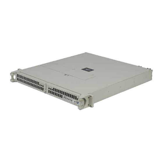
Themis RES-XR4-1U Installation Manual (198 pages)
1RU 19” Rack-Mount Rugged Enterprise Server
Brand:
Themis
| Category:
Server
| Size: 3 MB
Table of Contents
Safety Instructions
7
Grounding Methods
9
Table of Contents
17
Table
29
Figure 1 Rugged Enterprise Server RES-XR4-1U
31
Preface
31
1 Overview and Specifications
35
Overview
35
Figure 1-1 RES-XR4-1U (with Front Doors Installed)
35
Table 1-1 Major Features of RES-XR4-1U
36
External Features
37
Figure 1-2 RES-XR4-1U Front Panel Features
37
Table 1-2 RES-XR4-1U Motherboard Specifications
37
Figure
38
Figure 1-3 RES-XR4-1U Motherboard I/O Options
38
Front Panel and System Leds
39
Figure 1-4 Front Panel Leds and Indicators
39
Table 1-3 System Leds
40
Table 1-4 Power Supply LED Behavior
41
System Led
41
Rear Panel I/O
42
Figure 1-5 Rear Panel I/O for X9DRW Motherboard
42
Figure 1-6 Rear Panel I/O for X9DBU Motherboard
43
Figure 1-7 Rear Panel I/O for X9Sci-LN4F Motherboard
43
Table 1-5 Rear-Panel I/O Connectors
44
Block Diagrams
45
Figure 1-8 X9DRW Motherboard Block Diagram
45
Figure 1-9 X9DBU Motherboard Block Diagram
46
Figure 1-10 X9Sci Motherboard Block Diagram
47
Internal Views
48
Figure 1-11 Top View of RES-XR4-1U with X9DBU Motherboard
48
Figure 1-12 Top View of RES-XR4-1U with X9DRW Motherboard
49
Figure 1-13 Top View of RES-XR4-1U with X9Sci-LN4F Motherboard
50
Processor and Chipset Overview
51
C602/C606 Chipset
51
Main Features of the E5-2400/E5-2600 Series Processor and C602/ C606 Chipset
51
C204 Chipset
52
Main Features of the E3-1200 Series Processor and C204 Chipset
53
Special Features
53
Recovery from AC Power Loss
53
PC Health Monitoring
53
Environmental Temperature Control
54
Fan Status Monitor
54
System Resource Alert
54
Power Supply Monitoring
54
Sample I2C Commands
55
ACPI Features
56
Slow Blinking LED for Suspend-State Indicator
56
Super I/O
56
Overview of the Renesas SH7757
56
BMC Subsystem Features
57
Overview of the Nuvoton WPCM450 BMC
57
WPCM450R DDR2 Memory Interface
58
WPCM450R PCI System Interface
58
Other Features of the WPCM450 BMC Controller
58
Specifications
60
General
60
Table 1-6 RES-XR4-1U General Specifications
60
Electrical
61
System Power
61
Table 1-7 RES-XR4-1U Electrical Specifications
61
Output Voltage
62
Environmental
62
Electrostatic Discharge
62
Noise
62
Shock
62
Packaging and Shipping
63
Accessory Kit
63
Rack-Mount Slides (Optional)
64
RES System
65
2 Installation and Operation
69
Installation Procedures
69
Remove Protective Top Cover
69
Figure 2-1 Remove the RES-XR4-1U Protective Access Cover
70
Memory Modules
71
RES-XR4-1U Memory Capacity
71
Table
71
Table
72
Table 2-2 X9DBU-3/If MB Memory Population
72
Table 2-3 X9DRW-3/If MB Memory Population
72
Table 2-4 X9Sci-LN4F MB Memory Population
72
Table 2-5 X9DBU-3/If Optimal Memory Population
73
Table 2-6 X9DRW-3/If Optimal Memory Population
73
Table 2-7 X9Sci-LN4F Optimal Memory Population
73
Figure
74
Figure 2-2 Memory Module Slot Locations (X9DBU-3/If Motherboard)
74
Memory Module Location
74
Figure
75
Figure 2-3 Memory Module Slot Locations (X9DRW-3/If Motherboard)
75
Figure 2-4 Memory Module Slot Locations (X9Sci-LN4F Motherboard)
76
Figure 2-5 Remove RES-XR4-1U Air-Flow Deflector
77
Installation
77
Figure 2-6 Memory Module Removal
78
PCI Cards
79
Figure 2-7 Positioning of the RES-XR4-1U PCI/UIO Riser Cards
79
Installing Cards
80
Figure 2-11 Installation of the PCI Card Retainer Bracket
82
Lithium Battery
83
Figure 2-12 Lithium Battery
83
Removing the Lithium Battery
83
Installing a Lithium Battery
84
Storage Drive
85
Figure 2-14 Opening the RES-XR4-1U Front Doors
85
Opening the RES-XR4-1U Front Doors
85
Figure 2-15 Unlocking the RES-XR4-1U Storage Drives
86
Storage-Drive Removal
86
Figure 2-16 RES-XR4-1U Storage Drive Removal
87
Storage Drive Installation
88
Cooling Fans
88
Removing and Installing the 40-MM Fan Assembly
88
Power Supply
90
DC Power Supply Option
90
Figure 2-17 DC Power Supplies
90
Removing a Power Supply
91
Figure 2-18 Remove each Power Cord from the RES-XR4-1U Rear Chassis
91
Figure 2-19 Remove the Power Cord Retention Bracket
92
Chassis Grounding Screw
93
Figure 2-21 the RES-XR4-1U Power Supply Locking Mechanism
94
Installing a Power Supply
94
Figure 2-22 Install the Power Cord Retention Bracket
95
Installing a Power Cord Retention Bracket
95
Figure 2-23 the RES-XR4-1U Power Cord Retention Bracket
96
Figure 2-24 the RES-XR4-1U USB Cable Retention Bracket
97
Installing a USB Cable Retention Bracket
97
Rack Mounts
98
Mounting Brackets
98
Rack-Mount Slides (Optional)
98
Operation
99
Figure 2-26 AC Power Socket and LED on the RES-XR4-1U Rear
99
Figure 2-27 System Power Button and LED on the RES-XR4-1U Front
99
Plugging in the AC Power Cords
99
Turning the System on
99
Configuration
100
Getting Started
100
Linux Installation
100
Turning the System off
100
3 BIOS Setup Utility
101
Introduction
101
Starting BIOS Setup Utility
101
How to Change the Configuration Data
102
Starting the Setup Utility
102
Main BIOS Setup
103
System Overview
103
Figure 3-1 Main BIOS Setup Screen
103
System Time/System Date
103
Ami Bios
104
Processor
104
System Memory
104
Advanced Setup Configuration
104
BOOT Features
105
Addon ROM Display Mode
105
Bootup Num-Lock
105
Figure 3-2 Advanced Setup Screen
105
Quiet Boot
105
Interrupt 19 Capture
106
Wait for 'F1' if Error
106
Power Configuration
106
Watch Dog Function
106
Power Button Function
106
Restore on AC Power Loss
106
CPU Configuration
106
Socket 1 CPU Information/Socket 2 CPU Information
107
CPU Speed
107
Clock Spread Spectrum
107
Hyper-Threading
107
Active Processor Cores
107
Limit CPUID Maximum
108
Execute-Disable Bit Capability
108
Intel AES-NI
108
Hardware Prefetcher
108
Adjacent Cache Line Prefetcher
108
DCU Streamer Prefetcher
108
DCU IP Prefetcher
108
Intel Virtualization Technology
109
CPU Power Management Configuration
109
Power Technology
109
Chipset Configuration
111
Northbridge Configuration
111
Iio 2 Pcie Port
112
Iio 3 Pcie Port
112
QPI (Quick Path Interconnect) Configuration
112
Current Qpi Link
112
Current Qpi Frequency
112
Qpi Link Speed Mode
112
Qpi Link Frequency Select
112
DIMM Configuration
113
DIMM Information
113
Memory Mode
113
Current Memory Mode
113
Current Memory Speed
113
Channel Interleaving
114
Dram Rapl Mode
114
Ddr Speed
114
Rank Interleaving
114
Patrol Scrub
114
Demand Scrub
114
Southbridge Configuration
115
Data Scrambling
115
Device Tagging
115
Thermal Throttling
115
All Usb Devices
115
SATA Configuration
116
SATA Port0~Sata Port5
116
SATA Mode
116
Ahci Mode
117
Raid Mode
117
SCU (Storage Control Unit) Configuration
117
Storage Controller Unit
117
Onchip SCU Option ROM
118
SCU Port 0-SCU Port 7
118
Pcie/Pci/Pnp Configuration
118
PCI ROM Priority
118
PCI Latency Timer
118
Above 4G Decoding
118
PERR# Generation
118
SERR# Generation
118
Maximum Payload
119
ASPM Support
119
Cpu1 Sxb 1A Oprom/Cpu1 Sxb 1B Oprom/Cpu1
119
Maximum Read Request
119
Onboard LAN Option ROM Select
119
Change Settings
120
Device Settings
120
Load Onboard LAN1 Option Rom/Load Onboard LAN2 Option ROM
120
Network Stack
120
Serial Port
120
Serial Port 1 Configuration
120
Super IO Configuration
120
VGA Priority
120
Change Settings
121
Device Mode
121
Device Settings
121
Serial Port
121
Serial Port 2 Attribute
121
Serial Port 2 Configuration
121
Serial Port Console Redirection
121
Console Redirection Settings
122
Stop Bits
122
Console Redirection Settings (for EMS)
123
Flow Control
123
Legacy os Redirection
123
Putty Keypad
123
Recorder Mode
123
Resolution 100X
123
Serial Port for Out-Of-Band Management/Windows Emergency Management Services (EMS)
123
Vt-Utf8 Combo Key Support
123
ACPI Settings
124
ACPI Sleep State
124
Data Bits, Parity, Stop Bits
124
Out-Of-Band Management Port
124
Configuration
125
High Precision Event Timer
125
NUMA (NON-Uniform Memory Access)
125
Pending Operation
125
Tpm State
125
Tpm Support
125
Trusted Computing
125
Current Status Information
126
Intel TXT (LT-SX) Configuration Settings
126
Intel TXT (LT-SX) Hardware Support
126
Intel ® TXT (LT-SX) Configuration
126
Tpm Active Status
126
Tpm Enable Status
126
Tpm Owner Status
126
Intel TXT (LT-SX) Dependencies
127
Intel ® ME Subsystem
127
Iscsi Configuration
127
Iscsi Initiator Name
127
NIC Configuration
128
Blink Leds (Range 0~15 Seconds)
128
Link Speed
128
Port Configuration Information
128
Wake on LAN (WOL)
128
Event Logs
129
Change SMBIOS Event Log Settings
129
Enabling/Disabling Options
129
Figure 3-3 Event Log Screen
129
Erasing Settings
130
SMBIOS Event Log Standard Settings
130
Erase Event Log
130
Log System Boot Event
130
MECI (Multiple Event Count Increment)
130
METW (Multiple Event Count Time Window)
130
Pci Error Logging Support
130
View SMBIOS Event Log
131
View System Event Log
131
Ipmi
132
Ipmi Firmware Revision
132
System Event Log
132
Enabling/Disabling Options
132
Figure 3-4 IPMI Settings Screen
132
Ipmi Status
132
Custom EFI Logging Options
133
Erasing Settings
133
BMC Network Configuration
133
Erase Sel
133
LAN Channel 1
133
When Sel Is Full
133
Configuration Address Source
134
Station Ip Address
134
Subnet Mask
134
Boot Configuration
135
CSM Support
135
Boot Option Priorities
135
Boot Option #1~ Boot Option #4
135
Figure 3-5 Boot Settings
135
USB Device BBS Priorities
136
Hard Disk Drives
136
Network Drives
136
Delete Boot Options
136
Delete Boot Option
136
Security Settings
137
Administrator Password
137
User Password
137
Figure 3-6 Security Settings Screen
137
Save and Exit
138
Discard Changes and Exit
138
Save Changes and Reset
138
Figure 3-7 Exit Setting Screen
138
Save Options
139
Boot Override
139
Discard Changes
139
Restore Optimized Defaults
139
Restore User Defaults
139
Save as User Defaults
139
Save Changes
139
BIOS Error Beep Codes
140
Table 3-1 BIOS Error Beep Codes
140
BIOS Recovery
141
Boot Sector Recovery from a USB Device
141
How to Recover the AMIBIOS Image (the Main BIOS Block)
141
Boot Sector Recovery from a Serial Port ("Serial Flash")
142
Boot Sector Recovery from an IDE CD-ROM
142
Figure 3-1 AMI_FLSH Hyperterminal
144
Figure 3-2 ROM File Extraction
144
Figure 3-3 FLASH Recovery
145
Appendix A. Connector Pinouts
147
PS/2 Keyboard and Mouse
147
PS/2 Keyboard/Mouse Pinouts and Signal Definitions
147
Table
147
USB Ports
148
Serial Ports
148
COM1 Serial Connector Pinout
148
USB Connector Signal Definitions
148
Table A-3 COM 1 Serial Connector Signal Definitions
148
Gigabit Ethernet LAN Ports
149
Figure A-3 Ethernet Connector, Type RJ45
149
Figure
149
Table A-4 RJ45 Ethernet Pinout Signals
149
VGA Display Port
150
Unit Identifier Switch
151
Appendix B. Rack-Mount Slide Installation
153
Appendix C. Red hat Enterprise Linux 5 Installation
157
Introduction
157
Installation
157
Appendix D. Optional RES Audio/Usb/Serial Port Module
177
RES Audio/Usb/Serial Port Custom Module
177
Attach I/O Cables
179
USB Ports a and B
179
Dual USB Connector Pinouts
180
Figure
180
Serial Port COM1
181
Stereo Audio Connector Pinout
182
Packaging Components
186
Advertisement
Advertisement
Related Products
Themis RES-XR4-3U
Themis RES-22DCX
Themis RES-11XR3
Themis RES-32XR3/FIO
Themis RES-32XR3-S
Themis RES-12DCX
Themis RES-22XR3
Themis RES-12XR3
Themis RES-21XR3
Themis RES-22XR3-S
Themis Categories
Server
Barcode Reader
Motherboard
Laboratory Equipment
Video Card
More Themis Manuals
Login
Sign In
OR
Sign in with Facebook
Sign in with Google
Upload manual
Upload from disk
Upload from URL