Themis RES-22XR3 Installation Manual
2ru 19" rack-mount rugged enterprise server with x8dth-if/x8dth-6f motherboard configuration/two quad/dual-core 5500 or quad/six-core 5600 xeon cpus
Hide thumbs
Also See for RES-22XR3:
- Installation manual (144 pages) ,
- Installation manual (158 pages) ,
- Installation manual (142 pages)

Related Manuals for Themis RES-22XR3


Summary of Contents for Themis RES-22XR3
- Page 1 Installation Installation Manual Manual 2RU 19” Rack-Mount Rugged Enterprise Server with X8DTH-iF/X8DTH-6F Motherboard Configuration/ Two Quad/Dual-Core 5500 or Quad/Six-Core 5600 Xeon CPUs...
- Page 3 RES-22XR3 Installation Manual - Configuration 1* Version 1.3— April 2012 * SuperMicro Motherboards X8DTH-iF / X8DTH-6F Themis Computer—Americas and Pacific Rim Themis Computer—Rest of World 47200 Bayside Parkway 5 Rue Irene Joliot-Curie Fremont, CA 94538 38320 Eybens, France Phone (510) 252-0870...
- Page 4 Themis Computer assumes no responsibility for inaccuracies. Themis Computer retains the right to make changes to this publication at any time without prior notice. Themis Computer does not assume any liability arising from the application or use of this publication or the product(s) described herein.
-
Page 5: Version Revision History
RES-22XR3 Installation Manual - Configuration 1 Version Revision History Version 1.3 ..................April 2012 • Fixed page numbering error occurring in the appendices. • Fixed page numbering error occurring in the roman numeral pages. • Added the manual P/N throughout the manual for easier reference. - Page 6 RES-22XR3 Installation Manual - Configuration 1 Version 1.3 Version 1.2..................August 2011 • Added P/N 118188 to the manual matrix in Table 2 on page xxiii. • Modified footnote for Table 1-2, page 1-2. Added clarity regarding SAS/SATA support. • Added Table 1-3, page 1-7 describing LED behaviors related to the power sup- ply modules.
-
Page 7: Safety Instructions
In these cases, the device must be shut down and secured against unintentional operation. • Repairs may only be carried out by a person authorized by Themis Computer. • The device may only be opened for the installation and removal of extension... - Page 8 RES-22XR3 Installation Manual - Configuration 1 Version 1.3 and the lithium battery—all in accordance with the instructions given in this manual. • If extensions are made to the device, the legal stipulations and the device spec- ifications must be observed.
- Page 9 RES-22XR3 Installation Manual - Configuration 1 2. Use anti-static mats, heel straps, or air ionizers to give added protection. 3. Handle electrostatic-sensitive components, boards, and assemblies by the case or the PCB edge. 4. Avoid contact with pins, leads, or circuitry.
- Page 10 RES-22XR3 Installation Manual - Configuration 1 Version 1.3 viii Themis Computer...
-
Page 11: Table Of Contents
1.9 Specifications ....................... 1-15 1.9.1 General ..................... 1-15 1.9.2 Electrical ....................1-16 1.9.2.1 System Power ................1-16 1.9.2.2 Output Voltage ................1-16 1.9.3 Environmental ..................1-17 1.9.3.1 Shock ..................1-17 1.9.3.2 Electrostatic Discharge ............. 1-17 1.9.3.3 Noise ..................1-17 Themis Computer... - Page 12 2.1.4.1 Removing the Lithium Battery ........... 2-8 2.1.4.2 Installing a Lithium Battery ............2-9 2.1.5 SAS/SATA II Storage Drive ..............2-9 2.1.5.1 Opening the RES-22XR3 Front Doors ........2-9 2.1.5.2 Storage-Drive Removal ............2-10 2.1.5.3 Storage-Drive Installation ............2-11 2.1.6 Removable 80-mm Fan ................2-12 2.1.6.1 Removing and Installing a 80-mm Fan ........
- Page 13 3.3.2.13 C1E Support ................3-9 3.3.2.14 Intel® C-STATE Tech ..............3-9 3.3.2.15 C-State package limit setting ............3-9 3.3.2.16 C1 Auto Demotion ..............3-9 3.3.2.17 C3 Auto Demotion ..............3-10 3.3.2.18 ACPI T State ................3-10 3.3.3 Advanced Chipset Control ............... 3-10 Themis Computer...
- Page 14 RES-22XR3 Installation Manual - Configuration 1 Version 1.3 3.3.3.1 QPI Links Speed ............... 3-10 3.3.3.2 QPI Frequency ................3-10 3.3.3.3 QPI L0s and L1 ................. 3-10 3.3.3.4 Memory Frequency ..............3-10 3.3.3.5 Memory Mode ................3-11 3.3.3.6 Demand Scrubbing ..............3-11 3.3.3.7 Patrol Scrubbing ...............
- Page 15 3.3.11 IPMI Configuration .................. 3-25 3.3.11.1 IPMI Firmware Revision ............3-25 3.3.11.2 Status of BMC ................3-25 3.3.12 View BMC System Event Log ..............3-26 3.3.12.1 Clear BMC System Event Log ..........3-26 3.3.13 Set LAN Configuration ................3-26 xiii Themis Computer...
- Page 16 RES-22XR3 Installation Manual - Configuration 1 Version 1.3 3.3.13.1 Channel Number ............... 3-26 3.3.13.2 Channel Number Status ............3-27 3.3.13.3 IP Address Source ..............3-27 3.3.13.4 BMC Watch Dog Timer Action ..........3-27 3.3.14 Event Log Configuration ................. 3-28 3.3.14.1 View Event Log ................ 3-28 3.3.14.2 Mark all events as read .............
- Page 17 E.2 Ordering the RES Audio/USB/Serial Port Custom Module ........E-7 Appendix F. Re-packaging Instructions ................. F-1 F.1 Re-packaging for Shipment ................... F-1 F.2 Packaging Components ..................F-2 F.3 Instructions for Re-packaging ................F-3 Index ..........................Index-1 Reader Comment Card Themis Computer...
- Page 18 RES-22XR3 Installation Manual - Configuration 1 Version 1.3 Themis Computer...
- Page 19 RES-22 System LEDs and I/O Connectors (Configuration 1) ......1-5 Figure 1-5 Major Components of the RES-22 (Open Top View) ........1-6 Figure 1-6 RES-22XR3 with Front Sound Baffle Installed (Front View) ...... 1-17 Figure 1-7 RES-22XR3 with Rear Sound Baffle Installed (Rear View)......1-18 Figure 2-1 Remove the RES-22XR3 Protective Access Cover.........
- Page 20 Right Rack-Mount Bracket ................2-17 Figure 2-16 AC Power Socket and LED on the RES-22XR3 Rear........2-18 Figure 2-17 System Power Button and LED on the RES-22XR3 Front ......2-18 Figure 3-1 Main BIOS Setup Screen ................. 3-3 Figure 3-2 Advanced Settings ...................
- Page 21 RES-x2XR3 20”-Deep Chassis Manual Matrix ..........xxii Table 2 RES-x2XR3S / RES-x1XR3 17”-Deep Chassis Manual Matrix....xxiii Table 3 Front I/O 16”-Deep Chassis Manual Matrix..........xxiv Table 1-1 RES-22XR3 Motherboard Options—Configuration 1 ........1-2 Table 1-2 Major Features of the RES-22—Configuration 1........... 1-2 Themis Computer...
- Page 22 Table 1-8 Approximate Weights of the RES Series............1-20 Table 2-1 RES-22XR3 Memory Capacity ..............2-3 Table 2-2 RES-22XR3 Optimal Memory Population—Two CPUs Installed....2-3 Table 3-1 PIO Mode Select Options ................3-15 Table 3-2 DMA Mode Select Options ................3-16 Table A-1 PS/2 Keyboard/Mouse Pinouts and Signal Definitions .........
-
Page 23: Preface
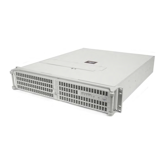
Preface This document, entitled RES-22XR3 Installation Manual—Configuration 1, pro- vides instructions on how to install, configure, power up, and boot the Themis Rug- ged Enterprise Server RES-22XR3 Configuration 1 (see Figure 1 below), which is ® ® based on two 64-bit Intel... -
Page 24: Table 1 Res-X2Xr3 20"-Deep Chassis Manual Matrix
RES-22XR3 Installation Manual - Configuration 1 Version 1.3 Table 1. RES-x2XR3 20”-Deep Chassis Manual Matrix RES-22XR3 RES-32XR3 RES-22XR3 RES-12XR3 with Riser Category Motherboard Manual Manual Manual Manual kets Part Number Part Number Part Number Part Number X8DTH-iF Configuration 1 116790-024... -
Page 25: Table 2 Res-X2Xr3S / Res-X1Xr3 17"-Deep Chassis Manual Matrix
LN4 = Extra gigabit Ethernet controller for two extra ports z: F = IPMI blank = No IPMI a—The 17”-deep RES XR3 chassis actually measures 17.07” deep, but for simplicity will continue to be referred to as being 17” deep through- out these manuals. xxiii Themis Computer... -
Page 26: Figure 2 Front View Of A Standard Rear-I/O Res-22 Chassis (Doors Removed)
RES-22XR3 Installation Manual - Configuration 1 Version 1.3 A matrix describing RES chassis that are configured for front-I/O connector and front-PCI card access in a 16” chassis is given in Table 3, page xxiv. This chassis design makes it more convenient to install cables to the system and demands no access to the rear of the chassis except to replace a fan. -
Page 27: Figure 3 Rear View Of A Standard Rear-I/O Res-22 Chassis
Preface Figure 3. Rear View of a Standard Rear-I/O RES-22 Chassis Figure 4. Front View of a Front-I/O RES-22 Chassis Figure 5. Rear View of a Front-I/O RES-22 Chassis Themis Computer... - Page 28 RES-22XR3 Installation Manual - Configuration 1 Version 1.3 The 2RU-high (3.5”) RES-22XR3 has been designed to fit into a standard 19” rack and is provided with rack-mount brackets with handles. Optional rack-mount slides are also available. The RES-22XR3 is rugged enough to withstand extreme shock (up to 35G), vibration, temperature, and EMI associated with such demanding mar- kets as the military, aerospace, and telecommunications industries.
- Page 29 To reduce the risk, follow the in- structions accompanying this symbol. Sidebar: A “sidebar” adds detail to the section within which it is placed, but is not absolutely vital to the description or procedure of the section. xxvii Themis Computer...
- Page 30 RES-22XR3 Installation Manual - Configuration 1 Version 1.3 xxviii Themis Computer...
-
Page 31: Overview And Specifications
Chapter Overview and Specifications Overview The RES-22XR3 Configuration 1 (see Figure 1-1 below; a block diagram is given in Figure 1-2 on page 1-3) is a rack-mounted high-performance system designed specifically for above-average shock and vibration environments. The RES-22XR3 ™... - Page 32 RES-22XR3 Installation Manual - Configuration 1 Version 1.3 Table 1-1. RES-22XR3 Motherboard Options—Configuration 1 PCI-e, PCI-X, and PCI Slots Mother- Memory IPMI SATA Graphics Audio PCI-e PCI-e PCI-e board Slots PCI-X Slots X8DTH-iF — — — — — — 1–7...
-
Page 33: Figure 1-2 X8Dth-If/X8Dth-6F Motherboard Block Diagram
USB2.0 2 REAR+4 FRONT+1 TYPE A LPC BUS PCI 33MHz RTL8201N WPCM450 RMII_IPMI W83527HG LAN3 IPMI_LAN DDR II Note: SAS is supported directly from the COM1 motherboard on the X8DTH-6F only. External Figure 1-2. X8DTH-iF/X8DTH-6F Motherboard Block Diagram Themis Computer... -
Page 34: Figure 1-3 External Features Of The Res-22 (Front And Rear)
RAID, NIC, etc.), two power supply modules with latch locks and power-cord sock- ets, and all I/O connectors (See Figure 1-4). Major internal components of the RES-22XR3 can be seen in the open top view (cover removed) shown in Figure 1-5 on page 1-6. -
Page 35: System Leds And I/O Connectors
LAN 1 Port LAN 2 Port USB1 (top) Gigabit Ethernet USB0 (bottom) Figure 1-4. RES-22 System LEDs and I/O Connectors (Configuration 1) LEDs are described in Table 1-4 on page 1-8; I/O connectors are described in Table 1-5, page 1-9. Themis Computer... -
Page 36: Figure 1-5 Major Components Of The Res-22 (Open Top View)
RES-22XR3 Installation Manual - Configuration 1 Version 1.3 AC Power Supply AC Power Supply Air-Flow Deflector (12 DIMM Memory Modules underneath) Rear I/O Slots 1 to 7 PCI Slot 1 (PCI-Express 2.0 x8) (PCI-Express 2.0 x8) (PCI-Express 2.0 x8) (PCI-Express 2.0 x8) (PCI-Express 2.0 x8) -
Page 37: Table 1-3 Power Supply Led Behavior
LED behavior indicates that DC power is not being used, and the system is off. It does not indicate a loss of AC power to the power supply module(s). Themis Computer... -
Page 38: Table 1-4 System Leds
RES-22XR3 Installation Manual - Configuration 1 Version 1.3 Table 1-4. System LEDs Symbol Description Power Indicates that the system is turned on. Storage Drive Indicates SAS/SATA II storage-drive activity. ENET1 NIC1 (Gb Ethernet) Indicates network activity on LAN 1. -
Page 39: Table 1-5 Rear-Panel I/O Connectors
15-pin VGA connector to attach a monitor device. Standard RJ45 connectors to attach one or two gigabit Ethernet LAN Ethernet LAN Ports line(s)—LAN 1 and LAN 2. IPMI Dedicated LAN Standard RJ45 connector to attach a dedicated IPMI LAN line. Port Themis Computer... -
Page 40: Chipset Overview
RES-22XR3 Installation Manual - Configuration 1 Version 1.3 Chipset Overview Built upon the functionality and capability of the Intel 5520 platform, RES-22XR3 motherboards provide the performance and features required for dual processor- based high-end systems, including optimal configuration options for communica- tions, high-end CAD systems, presentation, computation or database applications. -
Page 41: Special Features
Setup section to change this setting. The default setting is Last State. PC Health Monitoring This section describes the PC health monitoring features of the RES-22XR3 mother- boards. All have an onboard System Hardware Monitor chip that supports PC health monitoring. -
Page 42: System Resource Alert
RES-22XR3 Installation Manual - Configuration 1 Version 1.3 threshold. The overheat circuitry runs independently from the CPU. Once it detects that the CPU temperature is too high, it will automatically turn on the thermal fan control to prevent any overheat damage to the CPU. The onboard chassis thermal circuitry can monitor the overall system temperature and alert users when the chassis temperature is too high. -
Page 43: Main Switch Override Mechanism
Both UARTs provide legacy speed with baud rate up to 115.2 Kbps, and an advanced speed with baud rates of 250K, 500K, or 1 Mb/s (for higher speed modems). 1-13 Themis Computer... -
Page 44: Winbond Wpcm450 Controller
RES-22XR3 Installation Manual - Configuration 1 Version 1.3 The Super I/O provides functions that comply with ACPI (Advanced Configuration & Power Interface), which includes support of legacy and ACPI power management through an SMI or SCI function pin. It also features auto power management to reduce power consumption. -
Page 45: Specifications
Non-Operating 0 to 40,000 feet above sea level a—Specifications are dependent on the configurations in this manual. b—These are “typical” specifications for a RES system. Please contact Themis for the exact specifications of your configured system. 1-15 Themis Computer... -
Page 46: Electrical
(SVS5-4 or equivalent) (SVS5-4 or equivalent) a—These are “typical” results from a RES system. Please contact Themis for information regarding your exact system configuration. b—Tested using a watt meter with a SuperMicro X8DA3 Motherboard, nVidia GeForce 9600 GT graphics card, Intel Dual/Quad-Core X5550 CPU @ 2.66GHz, and 32GB of RAM. -
Page 47: Environmental
Figure 1-6. RES-22XR3 with Front Sound Baffle Installed (Front View) Note: All RES systems are shipped with BIOS fan speed set to the quietest mode. The default fan speed control mode of the RES-22XR3 is Energy Saving/ES. Front Access—Opening the two front doors of the RES-22 requires removing the front sound baffle. -
Page 48: Figure 1-7 Res-22Xr3 With Rear Sound Baffle Installed (Rear View)
Left Side Right Side Figure 1-7. RES-22XR3 with Rear Sound Baffle Installed (Rear View) Rear Access—Accessing the I/O connectors and PCI cards on the rear of the RES- 22 requires opening the rear sound baffle door. To do this, loosen the four (4) captive knurled Phillips screws A holding the baffle door to the chassis and swing the door downward away from the chassis, exposing the rear connectors and PCI cards. -
Page 49: Packaging And Shipping
A. Two AC Power Cords B. Two storage drive Barrel Keys When you unpack the RES-22XR3, please verify that all of these items are included. If any of these items are missing or not as pictured, please call Themis Technical Support at 510-252-0870, or send an email to support@themis.com. -
Page 50: Rack-Mount Slides (Optional)
All storage drive bays filled RES-22XR3/FIO 21 lbs (kg) 13.6” 2 power supplies RES-32XR3/FIO 25 lbs (kg) 13.6” a—These are “typical” weights for a RES system. Please contact Themis for the exact weight of your configured system. 1-20 Themis Computer... -
Page 51: Installation And Operation
To install or replace a storage drive, fan, or power supply, skip the next section and proceed directly to page 2-9, page 2-12, or page 2-14, respectively. Replacement of motherboard components, however, requires removal of the protective cover. 2.1.1 Remove Protective Top Cover To access a motherboard component, open the RES-22XR3 as follows: Themis Computer... -
Page 52: Figure 2-1 Remove The Res-22Xr3 Protective Access Cover
1. Loosen the two captive Phillips screws holding the protective top access cover to the rear of the RES-22XR3 chassis (see A, Figure 2-1). 2. Both the front and sides of the cover have flat hooks or tabs underneath that fit under slots on the chassis top edges (see B, Figure 2-1). -
Page 53: Memory Modules
2—Installation and Operation Installation Procedures 2.1.2 Memory Modules The RES-22XR3 supports memory according to Table 2-1. Note the total memory capacity varies according to the motherboard installed in the RES-22XR3. Table 2-1. RES-22XR3 Memory Capacity Memory Parameters DDR3 Motherboard Number... -
Page 54: Installation
The following procedure explains how to install the DDR3 FBD Memory Modules. 1. Loosen and remove the eight (8) screws securing the air-flow deflector and PCI card retainer bracket to the RES-22XR3 chassis (see Figure 2-2). • Screw A—After removing the single screw A, remove the PCI card retainer bracket and store it in a safe place. -
Page 55: Figure 2-3 Memory Module Slot Locations
(see Figure 2-4 on page 2-6), then pulling the old module directly up from the slot until it is free of the connector. Themis Computer... - Page 56 RES-22XR3 Installation Manual - Configuration 1 Version 1.3 Press latch downward & outward at each end Figure 2-4. Memory Module Removal 4. Before inserting a new memory module into the vacant slot, make sure that the two latches are pulled outward away from the center of the slot.
-
Page 57: Pci Cards
2—Installation and Operation Installation Procedures 2.1.3 PCI Cards RES-22XR3 Configuration 1 supports seven PCI-Express 2.0 x8 slots (all in x16 slots). All slots support cards up to 12.28-inches long (see Figure 2-5). Slot Slots 1 through 7 PCI-Express 2.0 x8 (all in x16 slots) Figure 2-5. -
Page 58: Lithium Battery
7. Attach any internal I/O cables to the installed PCI cards, and carefully fold and tuck any exposed ribbon cables into the cabinet. 8. If you have no further installations to perform, close the RES-22XR3 chassis by refastening the top cover removed in Section 2.1.1, “Remove Protective Top Cover,”... -
Page 59: Installing A Lithium Battery
2.1.5.1 Opening the RES-22XR3 Front Doors The knurled captive screw on the front of the RES-22XR3 allows the doors to lock without a key. To unlock the doors, turn the screw counterclockwise and pull both doors away from the chassis. -
Page 60: Storage-Drive Removal
After opening the front doors, perform the following steps to remove and install a storage drive: Note: Since RES-22XR3 storage drives are “hot-swappable”, it is not necessary to electrically turn off system power in order to remove and replace a drive (ex- cept the operating system drive). -
Page 61: Storage-Drive Installation
The handle will swing closed when it comes into contact with the RES-22XR3 chassis. 4. When the drive is fully inserted in its slot, insert the key into the barrel lock and turn it 45 degrees counter-clockwise. -
Page 62: Removable 80-Mm Fan
See Figure 2-11 on page 2-12 for fan layout and descriptions. Note: Since RES-22XR3 fans are “hot-swappable”, it is not necessary to turn off system power in order to remove and replace a fan. -
Page 63: Removing And Installing A 80-Mm Fan
With the right hand index finger, press on the right hand side of the fan and pull the fan directly upward from the RES-22XR3 chassis. 3. When the fan is removed, its 4-wire connector will be disconnected from the chassis. -
Page 64: Power Supply
RES-22XR3 Installation Manual - Configuration 1 Version 1.3 Figure 2-12 on page 2-13) to engage the Locking contact area (see Figure 2-13 below) onto the locking stud. Locking Contact Area Rear of System Font of System Figure 2-13. Locking Contact area 2.1.7... -
Page 65: Figure 2-14 The Res-22Xr3 Power Supply Locking Mechanism
… then disengage locking lever and remove power supply Phillips Screw Hole (for knurled captive screw) System Power LED Phillips Screw Hole (for knurled captive screw) Extraction Handle Power Supply AC Outlet Locking Lever Figure 2-14. The RES-22XR3 Power Supply Locking Mechanism 2-15 Themis Computer... -
Page 66: Installing A Power Supply
RES-22XR3 Installation Manual - Configuration 1 Version 1.3 2.1.7.2 Installing a Power Supply Perform the following steps to install a power supply: 1. Insert the replacement power supply into an empty slot with the extraction handle and AC outlet facing to the right (see Figure 2-14). -
Page 67: Rack Mounts
To learn how to install rack-mount slides, refer to Appendix B, “Rack-Mount Slide Installation”. Caution: Any screws used to mount a slide to a RES-22XR3 chassis must not ex- ceed a length of 3/8” to prevent excessive penetration of the chassis. -
Page 68: Operation
Before powering on the RES-22XR3, plug in the AC power cords as follows: 1. On the rear of the RES-22XR3, plug an AC power cord (shipped with unit) into the AC power socket on each power supply (see Figure 2-16). -
Page 69: Getting Started
1. To turn the RES-22XR3 power off, press the system power on/off button (see Figure 2-17, page 2-18). This will shut down the system and turn off the POWER LED, as well as the LED on the power supply modules. -
Page 70: Res-22Xr3 Installation Manual - Configuration 1 Version
RES-22XR3 Installation Manual - Configuration 1 Version 1.3 2-20 Themis Computer... -
Page 71: Bios Setup Utility
3RES-22XR3 Installation Section Chapter BIOS Setup Utility Introduction This chapter describes the AMI BIOS Setup Utility for the RES-22XR3 mother- boards. Note: For BIOS recovery, please refer to the AMI BIOS Recovery posted at http://www.supermicro.com/support/manuals/. 3.1.1 Starting BIOS Setup Utility To enter the AMI BIOS Setup Utility screens, press the <Delete>... -
Page 72: How To Change The Configuration Data
RES-22XR3 Installation Manual - Configuration 1 Version 1.3 Note: The AMI BIOS has default text messages built in. Themis retains the op- tion to include, omit, or change any of these text messages. The AMI BIOS Setup Utility uses a key-based navigation system called “hot keys”. -
Page 73: Main Setup
<Enter>. Press the <Tab> key to move between fields. The date must be entered in Day MM/DD/YY format. The time is entered in HH:MM:SS format. Note: The time is in the 24-hour format. For example, 5:30 P.M. appears as 17:30:00. Themis Computer... -
Page 74: Supermicro X8Dth
RES-22XR3 Installation Manual - Configuration 1 Version 1.3 3.2.2 Supermicro X8DTH • Version: This item displays the BIOS revision used in your system. • Build Date: This item displays the date when this BIOS was completed. 3.2.3 Processor The AMI BIOS will automatically display the status of the processor used in your system: •... -
Page 75: Advanced Setup Configurations
This option allows the bootup screen options to be modified between POST mes- sages or the OEM logo. Select Disabled to display the POST messages. Select Enabled to display the OEM logo instead of the normal POST messages. The options are Enabled (default) and Disabled. Themis Computer... -
Page 76: Addon Rom Display Mode
RES-22XR3 Installation Manual - Configuration 1 Version 1.3 3.3.1.3 AddOn ROM Display Mode This sets the display mode for Option ROM. The options are Force BIOS (default) and Keep Current. 3.3.1.4 Bootup Num-Lock This feature selects the Power-on state for the Numlock key. The options are Off and On (default). -
Page 77: Restore On Ac Power Loss
3.3.2.4 Adjacent Cache Line Prefetch (Available when supported by the CPU) The CPU fetches the cache line for 64 bytes if this option is set to Disabled. The CPU fetches both cache lines for 128 bytes as comprised if Enabled (default). Themis Computer... -
Page 78: Mps And Acpi Madt Ordering
RES-22XR3 Installation Manual - Configuration 1 Version 1.3 3.3.2.5 MPS and ACPI MADT Ordering This feature allows the user to decide how to order the Multiple APIC Description Table (MADT). Select Modern Ordering for Microsoft Windows XP or a newer ver- sion of the OS. -
Page 79: Active Processor Cores
The options are Auto (default), C1, C3, C6 and C7. 3.3.2.16 C1 Auto Demotion When enabled, the CPU will conditionally demote C3, C6 or C7 requests to C1 based on un-core auto-demote information. The options are Disabled and Enabled (default). Themis Computer... -
Page 80: C3 Auto Demotion
RES-22XR3 Installation Manual - Configuration 1 Version 1.3 3.3.2.17 C3 Auto Demotion When enabled, the CPU will conditionally demote C6 or C7 requests to C3 based on un-core auto-demote information. The options are Disabled and Enabled (default). 3.3.2.18 ACPI T State Select Enabled to report Processor throttling in the ACPI. -
Page 81: Memory Mode
The options are 1-way, 2-way, and 4-way (default). 3.3.3.10 Throttling - Closed Loop Throttling improves reliability and reduces power in the processor by automatic voltage control during processor idle states. Available options are Disabled and Enabled (default). 3-11 Themis Computer... -
Page 82: Intel I/Oat
RES-22XR3 Installation Manual - Configuration 1 Version 1.3 NorthBridge Configuration 3.3.3.11 Intel I/OAT The Intel I/OAT (I/O Acceleration Technology) significantly reduces CPU overhead by leveraging CPU architectural improvements, freeing resources for more other tasks. The options are Disabled and Enabled (default). -
Page 83: Usb Functions
This feature allows the user to select the drive type for SATA#1. The options are IDE (default), RAID and AHCI. (When the option-RAID is selected, the item-ICH RAID Code Base will appear. When the option-AHCI is selected, the item-SATA AHCI will be available.) 3-13 Themis Computer... -
Page 84: Ich Raid Code Base
RES-22XR3 Installation Manual - Configuration 1 Version 1.3 3.3.4.3 ICH RAID Code Base (This feature is available when the option-RAID is selected) Select Intel to enable Intel's SATA RAID firmware to configure Intel's SATA RAID settings. Select Adaptec to enable Adaptec's SATA RAID firmware to configure Adaptec's SATA RAID settings. -
Page 85: Table 3-1 Pio Mode Select Options
Table 3-1. PIO Mode Select Options Option Selected PIO Mode Max. Transfer Rate PIO Mode 0 3.3 MB/s PIO Mode 1 5.2 MB/s PIO Mode 2 8.3 MB/s PIO Mode 3 11.1 MB/s PIO Mode 4 16.6 MB/s 3-15 Themis Computer... - Page 86 RES-22XR3 Installation Manual - Configuration 1 Version 1.3 DMA Mode Select Auto to allow the BIOS to automatically detect IDE DMA mode when the IDE disk drive support cannot be determined. The options are Auto (default), SWD- MAn, MWDMAn, and UDMAn. See Table 3-2, “DMA Mode Select Options”...
-
Page 87: Pci/Pnp Configuration
Intel Virtualization Technology allowing multiple operating systems to run simultaneously within a single computer via native sharing of the PCI-Express devices in order to enhance network connectivity and perfor- mance. The options are Enabled and Disabled (default). 3-17 Themis Computer... -
Page 88: Pci-E Slots 1~7 X8
RES-22XR3 Installation Manual - Configuration 1 Version 1.3 3.3.5.7 PCI-E Slots 1~7 x8 This feature allows you to Enable or Disable any of the PCI slots. The options are Enable (default) and Disable. 3.3.5.8 Onboard LAN Options ROM Select This feature allows the user to select the onboard LAN option ROM type. The options are iSCSI and PXE (default). -
Page 89: Serial Port 2 Attribute
This feature allows the user to set the flow control for Console Redirection. The options are None (default), Hardware, and Software. 3.3.7.5 Redirection After BIOS POST Select Disabled to turn off Console Redirection after Power-On Self-Test (POST). Select Always to keep Console Redirection active all the time after POST. 3-19 Themis Computer... -
Page 90: Terminal Type
RES-22XR3 Installation Manual - Configuration 1 Version 1.3 Select Boot Loader to keep Console Redirection active during POST and Boot Note: This setting may not be supported by some operating systems. Loader. The options are Disabled, Boot Loader, and Always (default). -
Page 91: Cpu 1 Temperature/Cpu 2 Temperature/System Temperature
The system may shut down if it continues for a long period to prevent damage to the CPU. User intervention: If the system buzzer and Overheat LED has activated, take action immediately by checking the system fans, chassis ventilation and room temperature to correct any problems. 3-21 Themis Computer... - Page 92 RES-22XR3 Installation Manual - Configuration 1 Version 1.3 Notes: 1. The CPU thermal technology that reports absolute temperatures (Cel- sius/Fahrenheit) has been upgraded to a more advanced feature by Intel in its newer processors. The basic concept is each CPU is embedded by unique tem- perature information that the motherboard can read.
-
Page 93: Voltage Readings
When this item is set to Enabled, APIC ACPI SCI IRQ is supported by the system. The options are Enabled and Disabled (default). 3.3.9.5 Headless Mode This feature is used to enable system to function without a keyboard, monitor and/or mouse attached The options are Enabled and Disabled (default). 3-23 Themis Computer... -
Page 94: High Performance Event Timer
RES-22XR3 Installation Manual - Configuration 1 Version 1.3 3.3.9.6 High Performance Event Timer Select Enabled to activate the High Performance Event Timer (HPET) that produces periodic interrupts at a much higher frequency than a Real-time Clock (RTC) does in synchronizing multimedia streams, providing smooth playback and reducing the dependency on other timestamp calculation devices, such as an x86 RDTSC Instruc- tion embedded in the CPU. -
Page 95: Ipmi Configuration
This item displays the current IPMI firmware revision. 3.3.11.2 Status of BMC Baseboard Management Controller (BMC) manages the interface between system management software and platform hardware. This is an informational feature which returns the status code of the BMC micro controller. 3-25 Themis Computer... -
Page 96: View Bmc System Event Log
RES-22XR3 Installation Manual - Configuration 1 Version 1.3 3.3.12 View BMC System Event Log This feature displays the BMC System Event Log (SEL). It shows the total number of entries of BMC System Events. To view an event, select an Entry Number and pressing <Enter>... -
Page 97: Channel Number Status
This feature allows the BMC to reset or power down the system if the operating sys- tem hangs or crashes. The options are Disabled (default), Reset System, Power Down, Power Cycle. If this feature is not set to Disabled, the following item will dis- play. 3-27 Themis Computer... -
Page 98: Event Log Configuration
RES-22XR3 Installation Manual - Configuration 1 Version 1.3 BMC Watch Dog TimeOut [Min:Sec] This feature sets a timed delay (in minutes or seconds before a system powers down or resets after an operating system failure is detected. The options are [5 Min] (default), [1 Min], [30 Sec], and [10 Sec]. -
Page 99: Security Settings
This item indicates if a user password has been entered for the system. “Not Installed” means that a user password has not been used. 3.4.3 Change Supervisor Password Select this feature and press <Enter> to access the submenu, and then type in a new Supervisor Password. 3-29 Themis Computer... -
Page 100: User Access Level
RES-22XR3 Installation Manual - Configuration 1 Version 1.3 3.4.4 User Access Level (Available when Supervisor Password is set as above) The Options are Full Access, View Only, Limited, and No Access • Full Access (default): This feature grants full User read and write access to the Setup Utility. -
Page 101: Boot Configuration
This feature allows the user to specify the boot sequence from all available Storage Drives. The settings are 1st boot device, 2nd boot device, and disabled. • 1st Drive - [SATA: XXXXXXXXX] • 2nd Drive - [SATA: XXXXXXXXX] 3-31 Themis Computer... -
Page 102: Removable Drives
RES-22XR3 Installation Manual - Configuration 1 Version 1.3 3.5.3 Removable Drives This feature allows the user to specify the boot sequence from available Removable Drives. The settings are 1st boot device, 2nd boot device, and Disabled. • 1st Drive - [USB: XXXXXXXXX] 3.5.4... -
Page 103: Exit Options
Discard Changes and Exit Select this option to quit the BIOS Setup without making any permanent changes to the system configuration, and reboot the computer. Select Discard Changes and Exit from the Exit menu and press <Enter>. 3-33 Themis Computer... -
Page 104: Discard Changes
RES-22XR3 Installation Manual - Configuration 1 Version 1.3 3.6.3 Discard Changes Select this option and press <Enter> to discard all the changes and return to the AMI BIOS Utility Program. 3.6.4 Load Optimal Defaults To set this feature, select Load Optimal Defaults from the Exit menu and press <Enter>. -
Page 105: Bios Recovery
Flashing the wrong BIOS can cause irreparable damage to the system. In no event shall Supermicro and Themis Computer be liable for direct, indirect, special, inci- dental, or consequential damages arising from a BIOS update. If you need to update the BIOS, do not shut down or reset the system while the BIOS is updating. -
Page 106: Boot Sector Recovery From An Ide Cd-Rom
RES-22XR3 Installation Manual - Configuration 1 Version 1.3 2. While turning the power on, press and hold <Ctrl> and <Home> at the same time until the USB Access LED Indicator comes on. This might take a few seconds. 3. Once the USB drive LED is on, release the <Ctrl> and <Home> keys. AMI- BIOS will issue beep codes to indicate that the BIOS ROM file is being updated. - Page 107 Note: Be sure to complete Steps a to c above quickly because you have a second or less to do so. 7. Once you've completed the instructions given, a screen will display to indicate that remote flashing is starting and the new BIOS file is being uploaded. 3-37 Themis Computer...
-
Page 108: Figure 3-6 Ami_Flsh Hyperterminal
RES-22XR3 Installation Manual - Configuration 1 Version 1.3 8. To use Hyper Terminal to transfer the XModem protocol by using the “Send File” dialog under the “Transfer” menu, follow the instructions below to com- plete XModem transfers. a. Select the “Transfer” menu and enter <Send>. -
Page 109: Figure 3-8 Flash Recovery
VT-100 and XModem protocols, including protocols designed for GNU/LINUX & BSD operating systems such as minicom. It is recommended that the terminal program be configured to use the 'CR/LF' style of line termina- tion. 3-39 Themis Computer... - Page 110 RES-22XR3 Installation Manual - Configuration 1 Version 1.3 3-40 Themis Computer...
-
Page 111: Appendix A. Connector Pinouts
I/O panel of the RES-22XR3. PS/2 Keyboard and Mouse The RES-22XR3 provides a 6-pin female mini-DIN connector for the PS/2 key- board, and another for the PS/2 mouse. Pinouts and signal definitions for both con- nectors are defined in Table A-1. -
Page 112: Usb Ports
Signal Name Signal Name PO– Serial Ports The RES-22XR3 supports one male DB9 serial port connector on the rear I/O panel (see Figure A-2)—TTYA (COM1). COM1 pinout signal descriptions are listed in Table A-3, page A-2. Figure A-2. COM1 Serial Connector Table A-3. -
Page 113: Svga Monitor Port
A—Connector Pinouts SVGA Monitor Port A Super-VGA connector is installed on the RES-22XR3 on the rear I/O panel. A pinout for this connector is given in Figure A-3, and connector-pin signals are described in Table A-4. Symbol SVGA Display Port Figure A-3. -
Page 114: Gigabit Ethernet Lan Port
The left LED, when lit (blinking), indicates LAN activity (network traffic). IPMI Dedicated LAN Port The single IPMI dedicated Ethernet LAN port on the RES-22XR3 rear I/O panel has identical pinout and signal descriptions as the LAN 1 and LAN 2 Ethernet ports described in the previous Section A.5, “Gigabit Ethernet LAN Port”. -
Page 115: Appendix B. Rack-Mount Slide Installation
An optional set of two rack-mount slides (left side and right side) is available for all RES-22 systems, and should be ordered at the time of purchase. The RES-22XR3 chassis contains six threaded screw holes on each side to accommodate #8-32 size screws (included with the rack-mount slide kit);... - Page 116 Push the system into the rack until the mounting brackets on the front of the chassis are flush with the front of the rack. 6. Secure the RES-22XR3 system to the 19” rack with two bolts on each side. Themis Computer...
-
Page 117: Figure B-2 Res-22Xr3 Rack-Mount Slide Installation
Attach both inside slide sections to the left and right sides of the RES-22XR3 chassis with #8-32 screws (included in slide kit) Note: Graphic shown above is for slide placement only; chassis shown may not be an accurate representation of the your RES-22XR3. Figure B-2. RES-22XR3 Rack-Mount Slide Installation... - Page 118 RES-22XR3 Installation Manual - Configuration 1 Version 1.3 Themis Computer...
-
Page 119: Appendix C. Red Hat Enterprise Linux 5 Installation
Installation Step 1: Insert the Redhat Enterprise Linux 5 DVD and Power on the system; you will see the first installation screen with a boot prompt, press “ENTER” to begin installation (see on page C-2 Figure C-1 Themis Computer... -
Page 120: Figure C-1 Power On After Linux Dvd Is Inserted Into Drive
RES-22XR3 Installation Manual - Configuration 1 Version 1.3 Figure C-1. Power On after Linux DVD is Inserted into Drive Step 2: Press the “tab” key to move focus to the “Skip” key, then press “Enter” key to Con- tinue (see Figure C-2). -
Page 121: Figure C-3 Welcome Screen
Selecting the appropriate language also helps target your time zone configuration later in the installation. The installation program tries to define the appropriate time zone based on what you specify on this screen (see Figure C-4 on page C-4). Themis Computer... -
Page 122: Figure C-4 Language Selection
RES-22XR3 Installation Manual - Configuration 1 Version 1.3 Figure C-4. Language Selection Once you select the appropriate language, click Next to continue. Step 5: Using your mouse, select the correct layout type (for example, U.S. English) for the keyboard you would prefer to use for the installation and as the system default (see Figure... -
Page 123: Figure C-5 Selecting Layout Type
Step 6: Enter the installation number, if you don’t have an installation number; select the Skip Entering Installation Number Radio Button. Click OK, and if you did not enter an installation number, you’ll be given a warning. Click Skip to continue (see Figure C-6 page C-6 Themis Computer... -
Page 124: Figure C-6 Enter Installation Number
RES-22XR3 Installation Manual - Configuration 1 Version 1.3 Figure C-6. Enter Installation Number Click Next to continue. Step 7: Partitioning allows you to divide your storage drive into isolated sections, where each section behaves as its own storage drive. Partitioning is particularly useful if you run multiple operating systems. -
Page 125: Figure C-7 Partitioning
If you have two or more drives, you can choose which drive(s) should contain this installation. Unselected drives, and any data on them, are not touched. To review and make any necessary changes to the partitions created by automatic partition- Themis Computer... -
Page 126: Figure C-8 Reviewing Option
RES-22XR3 Installation Manual - Configuration 1 Version 1.3 ing, select the Review option. After selecting Review and clicking Next to move forward, the partitions created for you in Disk Druid appear. You can make modifications to these parti- tions if they do not meet your needs (see Figure C-8). -
Page 127: Figure C-9 Creating A Custom Layout
Boot Loader will be Installed, you’ll need to use a third-party boot loader such as Partition Magic or Microsoft’s TLDR. Unless you want to set up a Boot Loader Password or Config- ure Advanced Boot Loader Options (see Figure C-10 on page C-10). Themis Computer... -
Page 128: Figure C-10 Setting Up Boot Loader
RES-22XR3 Installation Manual - Configuration 1 Version 1.3 Figure C-10. Setting Up Boot Loader To configure more advanced boot loader options, such as changing the drive order or pass- ing options to the kernel, be sure Configure advanced boot loader options is selected before clicking Next. -
Page 129: Figure C-11 Master Boot Record (Mbr
BIOS does not return the correct drive order. Changing the drive order may be useful if you have multiple SCSI adapters, or both SCSI and IDE adapters, and you want to boot from the SCSI device. Click Next. C-11 Themis Computer... - Page 130 RES-22XR3 Installation Manual - Configuration 1 Version 1.3 Step 12: The installation program automatically detects any network devices you have and displays them in the Network Devices list (see Figure C-12). Figure C-12. Network Devices List Step 13: Once you have selected a network device, click Edit. From the Edit Interface...
- Page 131 A red X appears indicating your selection. • You can also scroll through the list at the bottom of the screen to select your time zone. Using your mouse, click on a location to highlight your selection. C-13 Themis Computer...
- Page 132 RES-22XR3 Installation Manual - Configuration 1 Version 1.3 Figure C-14. Selecting Time Zone Click Next. Step 15: Setting up a root account and password is one of the most important steps during your installation. Your root account is similar to the administrator account used on Windows NT machines.
- Page 133 You can select package groups, which group components together according to function (for example, X Window System and Editors), individual packages, or a combination of the two. To select a component, click on the checkbox beside it C-15 Themis Computer...
- Page 134 RES-22XR3 Installation Manual - Configuration 1 Version 1.3 Figure C-16. Package Installation Default Screen Step 17: Select each component you wish to install. Once a package group has been selected, if optional components are available you can click on Optional packages to view which packages are installed by default, and to add or...
- Page 135 Step 18: Once you have selected the package groups of your choice, you get one last chance to go back before starting the installation process. Click Next if you’re happy with your on page C-18 choices, or click Back to make changes (see Figure C-18 C-17 Themis Computer...
- Page 136 RES-22XR3 Installation Manual - Configuration 1 Version 1.3 Figure C-18. Option to Review or Continue Click Next. Step 19: Installation Starts (see Figure C-19). Figure C-19. Installation Begins C-18 Themis Computer...
- Page 137 Do nothing — after the boot loader's timeout period, (by default, five seconds) the boot loader automatically boots the default boot entry. Do whatever is appropriate to boot Red Hat Enterprise Linux. One or more screens of mes- sages should scroll by. C-19 Themis Computer...
- Page 138 RES-22XR3 Installation Manual - Configuration 1 Version 1.3 Step 21: Eventually, a prompt or a GUI login screen (if you installed the X login: Window System and chose to start X automatically) appears (see Figure C-21). Figure C-21. Login Screen Step 22: Once logged in, you are ready to use the desktop (see Figure C-22).
-
Page 139: Appendix D. Optional Remote On/Off Switch
Optional Remote On/Off Switch Remote On/Off Configuration Customers interested in installing an optional switch from which to remotely turn the RES-22XR3 for X8DTH-iF/6F on or off are able to order a Remote On/Off Switch module that is easily installed in an available storage-drive bay (see Figure D-1, which shows the Remote On/Off Switch Module next to a RES-32XR3/FIO system). -
Page 140: Remote On-Only Configuration
If the RES-22XR3 for X8DTH-iF/6F is turned ON, pressing the switch OFF for less than 4 seconds will gracefully shut down the system through the BIOS; pressing the switch OFF for 4 seconds or more results in a “hard”... -
Page 141: Appendix E. Optional Res Audio/Usb/Serial Port Module
Customers interested in adding audio, USB, and serial port capabilities to the front of any RES system can easily order an optional RES Audio/USB/Serial Port Custom Module (see Figure E-1) that is installed at the Themis factory into an available stor- age-drive bay (see following Caution). - Page 142 Module to the RES motherboard, the RES Custom Module must be installed at the Themis factory before being shipped to the customer. Do not attempt to remove the RES Custom Module from its drive slot unless you have some hardware experience (see the following paragraph, Figure E-2, and Figure E-3 on page E-3.
-
Page 143: Attach I/O Cables
PCB (Printed Circuit Board) Attach the appropriate I/O Cables from the RES Custom Module to external devices. Port A Port B Stereo Audio Out Jack (Optional) USB Ports A and B DB9 Serial Port Figure E-3. Attach the Appropriate I/O Cables Themis Computer... -
Page 144: Figure
Figure E-4. Dual USB Connector Pinouts Table E-1. Dual USB Connector Pinout Signal Descriptions (J10) Signal Name Signal Name DM (Data Minus) DM (Data Minus) DP (Data Plus) DP (Data Plus) Ground Ground Cut Off for Keying No Connection Themis Computer... -
Page 145: Serial Port Com1
Serial Port COM1 Header Figure E-5. COM1 Serial Connector Pinout Table E-2. COM1 Serial Connector Pinout Signal Descriptions (J8 and J9) Signal Connected Signal Connected Signal Connected Name to J9 Pin Name to J9 Pin Name to J9 Pin Themis Computer... -
Page 146: Stereo Audio Ports (Optional
Figure E-6. Stereo Audio Connector Pinout Table E-3. Stereo Audio Out Connector Pinout Signal Descriptions (J1) Signal Name Signal Name Signal Name No Connection Data Minus Ground + 5 volts No Connection Ground No Connection Data Plus No Connection Themis Computer... -
Page 147: Ordering The Res Audio/Usb/Serial Port Custom Module
Ordering the RES Audio/USB/Serial Port Custom Module Because internal modifications must be made to the RES chassis in order to support the RES Audio/USB/Serial Port Custom Module, the Custom Module must be spec- ified on the purchase order for your RES system. Themis Computer... - Page 148 RES22XR3 Installation Manual - Configuration 1 Version 1.3 Themis Computer...
-
Page 149: Appendix F. Re-Packaging Instructions
Re-packaging Instructions Re-packaging for Shipment If it becomes necessary to return equipment to Themis Computer, it is very important that the equip- ment be shipped in the original packaging which provides adequate protection against crushing and moisture invasion. Failure to use original packaging materials, exactly as described in this appendix may invalidate the warranty. -
Page 150: Packaging Components
RES-22XR3 Installation Manual - Configuration 1 Version 1.3 Packaging Components The original packaging components are shown in Figure F-1. They comprise a packaging box, bottom crush-resistant layer, and top crush-resistant layer. The bottom and top crush-resistant layers are identi- cal components, each layer formed of two pieces of material fitted together as shown in Figure F-1. -
Page 151: Instructions For Re-Packaging
• Seal the top of the box with strong packaging tape, wrapping the tape completely around the box, both lengthwise, and crosswise. • Prepare for shipment in accordance with the instructions received from Themis Computer. Figure F-2. Order of Assembly... - Page 152 RES-22XR3 Installation Manual - Configuration 1 Version 1.3 Themis Computer...
-
Page 153: Index
IPMI Configuration 3-25 AMIBIOS flash chip 3-35 PCI/PnP Configuration 3-17 antistatic bags 2-1 Processor and Clock Options 3-7 antistatic wrist strap 2-1 Remote Access Configuration 3-19 ATA/133 IDE controller card 3-15 Set LAN Configuration 3-26 audio connectors E-3 Index-1 Themis Computer... - Page 154 RES-22XR3 Installation Manual - Configuration 1 Version 1.3 Super IO Device Configuration 3-18 Bootup Num-Lock 3-6 Trusted Computing 3-24 Hit ’Del’ Message Display 3-6 View BMC System Event Log 3-26 Interrupt 19 Capture 3-6 BIOS Recovery 3-35 Power Button Function 3-6...
- Page 155 Expansion slots 1-2 USB Serial Ports 1-9 I/O connectors 1-5 I/O faceplates 1-4 ICH10R (Southbridge) 1-2 Removing and Installing a 80-mm Fan 2-13 ICH10R + IOH-36D 1-10 Fan Status Monitor with Firmware Control 1-11 IDE Master/Slave 3-14 Index-3 Themis Computer...
- Page 156 RES-22XR3 Installation Manual - Configuration 1 Version 1.3 32-Bit Data Transfer 3-17 NIC1 (Gb Ethernet) 1-8 Block 3-15 NIC2 (Gb Ethernet) 1-8 DMA Mode 3-16 SAS/SATA storage drives (HDD) 1-8 LBA/Large Mod 3-15 system 1-4 PIO Mode 3-15 Linux Installation 2-19, C-1 S.M.A.R.T.
- Page 157 IOH PCI-E Max Payload Size 3-12 cord sockets 1-4 LED 2-19 power cords 2-18 onboard graphics 2-19 power supply 1-2, 2-1 Opening the RES-22XR3 Front Doors 2-9 installation 2-16 Operating temperature 1-2 locking mechanism 2-15 Optional Remote On/Off Switch D-1 Power Supply Module 1-7...
- Page 158 RES-22XR3 Installation Manual - Configuration 1 Version 1.3 ACPI T State 3-10 Flow Control 3-19 Active Processor Cores 3-9 Redirection After BIOS POST 3-19 Adjacent Cache Line Prefetch 3-7 Remote Access 3-19 C1 Auto Demotion 3-9 Serial Port Mode 3-19...
- Page 159 Input Frequency 1-16 Power Fail LED (Right) 1-7 Input Leakage 1-16 SAS/SATA storage drives (HDD) 1-8 Input Power 1-16 System Power 1-16 Input VA Rating 1-16 System Resource Alert 1-12 Input Voltage 1-16 Maximum Wet Bulb 1-15 Index-7 Themis Computer...
- Page 160 RES-22XR3 Installation Manual - Configuration 1 Version 1.3 TCG/TPM Windows Hardware Error Architecture 3-24 Execute TPM Command 3-25 TPM Enable/Disable Status 3-25 TPM Owner Status 3-25 XModem protocol 3-38 Indicate Physical 3-24 TPM Deactivated 3-25 TPM Owner 3-25 Technical Support ii, 1-19...
- Page 161 Place Stamp Here Themis Computer 47200 Bayside Parkway Fremont, CA 94538 Attn: Publications Department Fold here; tape at top to seal...
-
Page 162: Reader Comment Card
Reader Comment Card We welcome your comments and suggestions to help improve the RES-22XR3 Configuration 1 Installation Manual (P/N:116789-024). Please take time to let us know what you think about this manual. • Information provided in the manual was complete.
Need help?
Do you have a question about the RES-22XR3 and is the answer not in the manual?
Questions and answers