
Related Manuals for Themis RES-XR4-3U


Summary of Contents for Themis RES-XR4-3U
- Page 1 Installation Installation Manual Manual Version 1.3 Pa r t N u m b e r : 120918-024 Rac k- M ount Rugged Enter prise Ser ver with Multiple M other board Configurations / Xeon CPUs...
- Page 2 version version version version version version version version...
- Page 3 RES-XR4-3U Installation Manual* Version 1.3— June 2014 * SuperMicro Motherboards X9DRH-iF/-iTF / -7F/-7TF, X9DBL-iF/-3F, X9DR3-F Themis Computer—Americas and Pacific Rim Themis Computer—Rest of World 47200 Bayside Parkway 5 Rue Irene Joliot-Curie Fremont, CA 94538 38320 Eybens, France Phone (510) 252-0870...
- Page 4 Themis Computer assumes no responsibility for inaccuracies. Themis Computer retains the right to make changes to this publication at any time without prior notice. Themis Computer does not assume any liability arising from the application or use of this publication or the product(s) described herein.
- Page 5 RES-XR4-3U Installation Manual Version Revision History Version 1.3 ..................June 2014 • Added German translation to the safety section of this manual • Minor edits and changes throughout this manual Version 1.2 .................. January 2014 • Removed Appendix for the Remote on/off Module for XR3 •...
-
Page 6: Safety Instructions
(bay). Personal injury and equipment damage can occur. WARNING: All equipment connected to the product must conform to their standards WARNING: This Themis PRODUCT must be used in sheltered environments only, and at an altitude of less than 3048 meters (10,000 ft). - Page 7 In these cases, the device must be shut down and secured against unintentional operation. • Repairs/service may only be carried out by a Themis Computer qualified ser- vice technician. • Do not open the chassis, or perform services/repairs when the equipment is powered on, due to electrical shock hazard.
-
Page 8: Grounding Methods
RES-XR4-3U Installation Manual Version 1.3 not allow yourself to be exposed to this radiation. The laser system meets the code of Federal Regulations 21 CFR,1040 for the USA and Canadian Radiation Emitting Devices Act, REDR C 1370. Electrostatic Discharge (ESD) A sudden discharge of electrostatic electricity can destroy static-sensitive devices or micro-circuitry. - Page 9 RES-XR4-3U Installation Manual Safety Instructions 6. Turn off power and input signals before inserting and removing connectors or test equipment. Power is not considered off until all power supplies have been disconnected. 7. Keep the work area free of non-conductive materials such as ordinary plastic as- sembly aids and Styrofoam.
- Page 10 RES-XR4-3U Installation Manual Version 1.3 European Union Waste Disposal This section is for waste disposal by users in private households in the European Union. For all others, please follow all local and government guidelines in accordance with waste disposal and the symbol seen below.
-
Page 11: Sicherheitshinweise
Personenschäden und zur Beschädigung des Geräts führen. Warnhinweis: Alle Geräte, die an das Produkt angeschlossen werden, müssen ihren Standards entsprechen. Warnhinweis: Dieses THEMIS-Produkt darf nur in geschützten Umgebungen und in einer Höhe von weniger als 3.048 Metern (10.000 ft) eingesetzt werden •... - Page 12 In diesen Fällen muss das Gerät ausgeschaltet und gegen unbeabsichtigte Inbetriebnahme gesichert werden. • Reparaturen dürfen nur von Beauftragten der Firma Themis Computer durch- geführt werden. • Das Öffnen des Gerätes ist nur zulässig für den Ein- und Ausbau von Erweit- erungskarten (PCI), Speichermodulen, Festplatten, Lüftergehäusen, Netz-...
- Page 13 RES-XR4-3U Betriebshandbuch Sicherheitshinweise Sie sich dieser Strahlung keinesfalls aus. Das Lasersystem erfüllt die Anforderungen des Code of Federal Regulations 21 CFR,1040 (für die USA) und des Canadian Radiation Emitting Devices Act, REDR C 1370 (für Kanada). Elektrostatische Entladung (ESD) Eine plötzliche elektrostatische Entladung kann empfindliche Geräte oder Mikros- chaltungen zerstören.
- Page 14 RES-XR4-3U Betriebshandbuch Version 1.3 6. Verwenden Sie am Arbeitsplatz keine nichtleitenden Materialien, wie gewöhn- liche Kunststoffmontagehilfen oder Styropor. 7. Benutzen Sie leitende Werkzeuge (z.B. Messer, Schraubendreher und Staubsau- ger). 8. Legen Sie Laufwerke und Platinen immer mit der Bauteilseite nach unten auf die Schaumstoffunterlage.
-
Page 15: Table Of Contents
1.4.2.3 System Resource Alert .............. 1-20 1.4.3 Power Supply Monitoring ................ 1-20 1.4.3.1 I2C Notes .................. 1-20 1.4.3.2 Sample I2C Commands ............1-21 1.4.4 ACPI Features ..................1-21 1.4.5 Slow Blinking LED for Suspend-State Indicator ........1-21 xiii Themis Computer... - Page 16 2.1.4.2 Removing the Lithium Battery ..........2-13 2.1.4.3 .Installing a Lithium Battery ............. 2-14 2.1.5 SAS/SATA Storage Drive ............... 2-14 2.1.5.1 Opening the RES-XR4-3U Front Doors ........2-15 2.1.5.2 Storage-Drive Removal ............2-16 2.1.5.3 Storage Drive Installation ............2-18 2.1.6 Removable 120-mm Fan ................2-18 2.1.6.1 Removing and Installing an 120-mm Fan .........
- Page 17 3.3.2 Power Configuration .................. 3-6 3.3.2.1 Watch Dog Timer ............... 3-6 3.3.2.2 Power Button Function ............... 3-6 3.3.2.3 Restore on AC Power Loss ............3-7 3.3.3 CPU Configurations ................... 3-7 3.3.3.1 Socket 1/ Socket 2 CPU Information .......... 3-7 Themis Computer...
- Page 18 RES-XR4-3U Installation Manual Version 1.3 3.3.3.2 CPU Power Management Configuration ........3-9 3.3.4 Chipset Configuration ................3-12 3.3.4.1 North Bridge ................3-12 3.3.4.2 South Bridge ................3-17 3.3.5 SATA Configuration ................3-18 3.3.5.1 SATA Mode ................3-19 3.3.6 SCU Configuration .................. 3-20 3.3.6.1 Storage Controller Unit .............
- Page 19 3.8.3.1 Save Changes ................3-39 3.8.3.2 Discard Changes ............... 3-39 3.8.3.3 Restore Defaults ................ 3-39 3.8.3.4 Save As User Defaults .............. 3-39 3.8.3.5 Restore User Defaults ............... 3-39 3.8.3.6 Boot Override ................3-40 3.9 BIOS Error Beep Codes ..................3-40 xvii Themis Computer...
- Page 20 RES-XR4-3U Installation Manual Version 1.3 3.10 BIOS Recovery ....................3-41 3.10.1 How to Recover the AMI BIOS Image (the Main BIOS Block) ..... 3-41 3.10.2 Boot Sector Recovery from a USB Device ..........3-41 3.10.3 Boot Sector Recovery from an IDE CD-ROM ........3-42 3.10.4 Boot Sector Recovery from a Serial Port (“Serial Flash”) ......
- Page 21 X9DBL Block Diagram ................. 1-16 Figure 1-12 RES-XR4-3U with Noise Baffle Installed (Front View)....... 1-27 Figure 1-13 RES-XR4-3U with Rear Sound Baffle Installed (Rear View) ...... 1-28 Figure 1-14 RES-XR4-3U with Rear Baffle Open............1-29 Figure 2-1 Remove the RES-XR4-3U Protective Access Cover ........2-2 Figure 2-2 Remove Air-Flow Deflector Screws..............
- Page 22 The RES-XR4-3U Power Supply Locking Mechanism ........ 2-22 Figure 2-21 Right Rack-Mount Bracket ................2-24 Figure 2-22 AC Power Socket and LED on the RES-XR4-3U Rear ........ 2-25 Figure 2-23 System Power Button and LED on the RES-XR4-3U Front ......2-25 Figure 3-1 Main BIOS Setup Screen .................
- Page 23 Figure C-22 Ready to use the Desktop................C-20 Figure D-1 Audio/USB/Serial Port Custom Module............D-1 Figure D-2 Install the RES Audio/USB/Serial Port Custom Module ....... D-2 Figure D-3 Attach the Appropriate I/O Cables ..............D-3 Figure D-4 Dual USB Connector Pinouts ................. D-4 Themis Computer...
- Page 24 Figure E-1 Packaging Components..................E-2 Figure E-2 Order of Assembly................... E-3 List of Tables Table 1-1 Major Features of the RES-XR4-3U .............. 1-2 Table 1-2 RES-XR4-3U Motherboard Specifications ............ 1-3 Table 1-3 System LEDs ....................1-7 Table 1-4 Power Supply LED Behavior ................. 1-8 Table 1-5 I/O Connectors ....................
-
Page 25: Table
Table of Contents Table D-2 COM1 Serial Connector Pinout Signal Descriptions (J8 and J9) ....D-5 Table D-3 Stereo Audio Out Connector Pinout Signal Descriptions (J1) ...... D-6 xxiii Themis Computer... - Page 26 RES-XR4-3U Installation Manual Version 1.3 xxiv Themis Computer...
-
Page 27: Preface
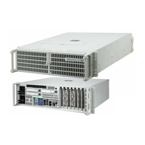
Preface This document, entitled RES-XR4-3U Installation Manual, provides instructions on how to install, configure, power up, and boot the Themis Rugged Enterprise Server RES-XR4-3U (see Figure 1 below). RES-XR4-3U supports the SuperMicro X9DRH and X9DR3 motherboards in either a 17” deep, front I/O chassis, or a 20”... - Page 28 Each 3RU-high (5.25”) RES-XR4-3U chassis has been designed to fit into a stan- dard 19” width rack and is provided with rack-mount brackets with handles.
- Page 29 To reduce the risk, follow the instructions accompanying this sym- bol. Sidebar: A “sidebar” adds detail to the section within which it is placed, but is not absolutely vital to the description or procedure of the section. xxvii Themis Computer...
- Page 30 RES-XR4-3U Installation Manual Version 1.3 xxviii Themis Computer...
-
Page 31: Overview And Specifications
General Section Chapter Overview and Specifications Overview The RES-XR4-3U is a rack-mounted high-performance system designed specifi- cally for above-average shock and vibration environments (see Figure 1-1 below). ® The RES-XR4-3U supports two Intel Xeon processors, each with a QPI (Quick- Path Interconnect) up to 8.0 GT/s (Giga-Transfers per second), supporting memory... -
Page 32: Table 1-1 Major Features Of The Res-Xr4-3U
Version 1.3 the E5-2600 version 2 processors which offer up to 12-core capabilities. Motherboards supported by RES-XR4-3U are listed in Table 1-1 on page 1-2. The RES-XR4-3U is designed within a 3RU-high (5.25”) form-factor 17” (43.2 cm) wide (which, with mounting brackets, fits a 19”-wide rack). Rack depths are depen- dent on the type of motherboard installed. -
Page 33: External Features
I/O panel contains I/O faceplates for seven PCI cards, two AC power supplies with latch locks and power-cord sockets, and all I/O connectors. Major internal compo- nents of the RES-XR4-3U can be seen in the open top views (cover removed) begin- ning on page 1-11. -
Page 34: Figure 1-2 External Features Of Res-Xr4-3U (Rear I/O)
20” (50.8 c) deep Slot 7 (not installed) Dual Power Supplies Rear View Power Supply Latch Lock AC Power Socket (3-prong NEMA 15) Slot 1 Rear I/O Panel (see Figure 1-5, page 1-7) Figure 1-2. External Features of RES-XR4-3U (Rear I/O) Themis Computer... -
Page 35: System Leds And Indicators
1.1.2 System LEDs and Indicators All RES-XR4-3U system LEDs are located on the front panel (see Figure 1-4 on page 1-6). System LEDs are described in Table 1-3 on page 1-7. Power supply LEDs are described in Table 1-4 on page 1-8. -
Page 36: Figure 1-4 Res-Xr4-3U System Leds And Indicators
Rear I/O Chassis Front Panel (Doors Open) LEDs ENET1 ENET2 < > < > Storage Power Power NIC1 NIC2 Overheat/ Power Drives Fail Fail Fan Fail (PS1) (PS2) Front I/O Chassis Front Panel Figure 1-4. RES-XR4-3U System LEDs and Indicators Themis Computer... -
Page 37: Table 1-3 System Leds
- Off = 10 MHz LAN1 and LAN2 - Green = 100 MHz - Amber = 1 GHz The right LED, when lit, indicates LAN activity. a—NIC = Network Interface Controller. b—X9DRH -iTF/-7TF support 10 Gigabit speeds Themis Computer... -
Page 38: Table 1-4 Power Supply Led Behavior
RES-XR4-3U Installation Manual Version 1.3 Table 1-4. Power Supply LED Behavior Symbol LED Power System LED Description If system is powered on, Power Fail LED warns that the left power (Left Power Supply) (red LED) supply has failed or has Note: system is powered on lost AC input. -
Page 39: I/O Connectors
USB3 (top) USB0 (bottom) USB2 (bottom) I/O Connectors IPMI Dedicated LAN PS/2 Mouse/keyboard COM 1 Port LAN 1 Port LAN 2 Port USB1 (top) USB3 (top) VGA Port Gigabit Ethernet USB0 (bottom) USB2 (bottom) Figure 1-5. I/O Panel Diagrams Themis Computer... -
Page 40: Table 1-5 I/O Connectors
RES-XR4-3U Installation Manual Version 1.3 Table 1-5. I/O Connectors Connector Description PS/2 Mouse 6-pin mini-DIN (female) connector to attach a PS/2 mouse device. PS/2 Keyboard 6-pin mini-DIN (female) connector to attach a PS/2 keyboard device. Two or four (motherboard dependent) 4-pin USB connectors to attach... -
Page 41: Internal Views
1.1.4 Internal Views Power Supplies CPU 2 and adjacent memory slots PCIe Slots CPU 1 and adjacent memory slots 120-mm Fans CD/DVD Combo-Drive Storage Drive (1 of 8) Housing Figure 1-6. RES-XR4-3U (Open Top View) (X9DRH Motherboard) 1-11 Themis Computer... -
Page 42: Figure 1-7 Res-Xr4-3U (Open Top View) (X9Dbl Motherboard)
Version 1.3 Power Supplies PCIe Slots CPU 2 and adjacent memory slots Lithium Battery CPU 1 an adjacent memory s 120-mm Fans CD/DVD Storage Drive (1 of 8) Combo-Drive Housing Figure 1-7. RES-XR4-3U (Open Top View) (X9DBL Motherboard) 1-12 Themis Computer... -
Page 43: Figure 1-8 Res-Xr4-3U (Open Top View) (X9Dr3 Motherboard)
Power Supplies CPU 2 and adjacent memory slots PCIe Slots Lithium Battery Lithium Battery CPU 1 and adjacent memory slots 120-mm Fans CD/DVD Storage Drive (1 of 8) Combo-Drive Housing Figure 1-8. RES-XR4-3U (Open Top View) (X9DR3 Motherboard) 1-13 Themis Computer... -
Page 44: Block Diagrams
RES-XR4-3U Installation Manual Version 1.3 Block Diagrams 1.2.1 X9DRH Block Diagram #H-2 #H-1 #G-2 #D-2 #G-1 #F-2 #C-2 #F-1 #C-1 #E-2 #B-2 #E-1 #B-1 E5-2600 E5-2600 #A-2 8 SNB CORE 8 SNB CORE DDR-III #A-1 DDR-III (CPU1) (CPU2) #3A #3C... -
Page 45: X9Dr3 Block Diagram
Ports 0~3 LANE1/2/3/4 (SCU4~7: Ports 4~7 X9DR3-F only) LANE5 PCH C606/C602 3.0 Gb/S LANE6 6.0 Gb/S (for Ports 0/1) PCI-32 USB 2.0 COM1 COM2 1 Type-A Header Header 2 Rear 4 Front Figure 1-10. X9DR3 Block Diagram 1-15 Themis Computer... -
Page 46: X9Dbl Block Diagram
RES-XR4-3U Installation Manual Version 1.3 1.2.3 X9DBL Block Diagram #C-1 #F-1 #B-1 #E-1 #A-1 #D-1 CPU 1 CPU 2 DDR 3 DDR 3 4GB/s PCI-E X4 Gen3 PCI-E X8 Gen3 PCI-E X8 Gen3 PCI-E X16 Gen3 PCI-E X8 Gen3 PCI-E x4 PEG0 6.0 Gb/S... -
Page 47: Chipset Overview
(X9DR3 & X9DRH)(Socket R) and the PCH C602 Chipset, or the Intel E5-2400 V2 (X9DBL)(Socket B2) and the PCH C602/C606 Chipset. RES-XR4-3U provides the performance required for dual processor-based high-end systems, including opti- mal configuration options for communications, high-end CAD systems, or database applications. - Page 48 RES-XR4-3U Installation Manual Version 1.3 1.3.2 Main Features of the E5-2400/E5-2600 V2 Series Processor and C602/C606 Chipset ® This list includes the major features of the Intel E5-2400/E5-2600 V2 Series CPU ® and the Intel C602/C606 chipset families • Up to 12 processor cores and 20 Threads in each CPU •...
-
Page 49: Special Features
1.4.2.1 Fan Status Monitor The RES-XR4-3U has two 120-mm cooling fans for the motherboard components and one within each power supply. The PC health monitor utility can be used to check the RPM status of cooling fans. The onboard CPU and chassis fans are con- trolled by Thermal Management via BIOS. -
Page 50: System Resource Alert
1.4.3 Power Supply Monitoring The power supplies in the Themis RES servers support a feature allowing their status to be queried directly through software. The power supplies are connected to an I bus used for system monitoring. This bus can be reached through the Baseboard Management Controller (BMC), (described in subsequent paragraphs), on the moth- erboard. -
Page 51: Sample I2C Commands
When the CPU enters a suspend state, the Power LED will start blinking to indicate that the CPU is in suspend mode. Pressing any key on the keyboard will awaken the CPU, at which time the power LED will stop blinking and remain on. 1-21 Themis Computer... -
Page 52: Super I/O
RES-XR4-3U Installation Manual Version 1.3 1.4.6 Super I/O The Super I/O supports two high-speed,16550 compatible serial communication ports (UARTs). Each UART includes a 16-byte send/receive FIFO, a programmable baud rate generator, complete modem control capability and a processor interrupt system. Both UARTs provide legacy speed with baud rate of up to 115.2 Kbps as well as an advanced speed with baud rates of 250 K, 500 K, or 1 Mb/s, which sup- port higher speed modems. -
Page 53: Additional Supported Features Of The Wpcm450R
• Supports Management tools: IPMIView, CLI (Command Line Interface) • RMCP+ protocol supported Note: For more information on the Motherboard’s IPMI configuration, please re- fer to the IPMI User’s Guide posted on the SuperMicro website at, www.super- micro.com/support/manuals/. 1-23 Themis Computer... -
Page 54: Specifications
RES-XR4-3U Installation Manual Version 1.3 Specifications 1.5.1 General specifications for the RES-XR4-3U Table 1-6. RES-XR4-2U General Specifications Parameter Description Dimensions 5.25” (3RU) high 17” (43.2 cm) wide (19” rack-mountable) 20” (50.8 cm), 17” (43.2 cm) or 14” (35.6 cm) deep ... -
Page 55: System Power
= Not Applicable. 1.5.1.1 System Power The RES-XR4-3U operates with two N+1 redundant power supplies of 750-watts capacity each that auto-range single-phase AC input from 100 to 240 Vac (47 to 63 Hertz) sources. Filtered and fused (internal) AC is supplied to each power supply connection. -
Page 56: Output Voltage
The RES-XR4-3U conforms to the 54-db noise specification. It is possible to achieve further noise reduction by installing a sound baffle on both the front and rear of the RES-XR4-3U chassis (See Figure 1-12 on page 1-27 and Figure 1-13 on page 1-28). Call your Themis representative for additional information. -
Page 57: Figure 1-12 Res-Xr4-3U With Noise Baffle Installed (Front View)
Figure 1-12. RES-XR4-3U with Noise Baffle Installed (Front View) Note: All RES systems are shipped with BIOS fan speed set to the quietest mode. The default fan speed control mode of the RES-XR4-3U is Energy Saving/ES. Front Access—Opening the two front doors of the RES-XR4-3U requires removing the front sound baffle. -
Page 58: Figure 1-13 Res-Xr4-3U With Rear Sound Baffle Installed (Rear View)
Rear Access—Accessing the I/O connectors and PCI card I/O on the rear of the RES-XR4-3U requires opening the rear sound baffle door. To do this, loosen the four (4) captive knurled Phillips screws (A in Figure 1-13) holding the baffle door to the chassis and swing the door downward away from the chassis, exposing the rear con- nectors and PCI cards. -
Page 59: Figure 1-14 Res-Xr4-3U With Rear Baffle Open
1—Overview and Specifications Specifications Figure 1-14. RES-XR4-3U with Rear Baffle Open Removing the protective top cover for access to the interior requires that the rear sound baffle be totally removed (this can be done with the baffle door closed). To do this, five (5) M3x4 flathead Phillips screws (B in Figure 1-13, page 1-28) must be removed, two on each side of the baffle and one (captive) in the middle on the top. -
Page 60: Packaging And Shipping
AC power cords is 8.8 pounds (4 kg). The approximate weight of a RES-XR4-3U (loaded with 2 CPUs, 6 DIMMs, 2 stor- age drives, 2 full-length PCI cards, a CD-RW/DVD-ROM drive, and 2 power sup- plies) is approximately 28.5 pounds (13 kg). -
Page 61: Rack-Mount Slides (Optional)
1.6.2 Rack-Mount Slides (Optional) Rack-Mount Slides can be mounted on each side of the RES-XR4-3U for the pur- pose of sliding the unit in and out of a rack. Mounting slides are optional and can be ordered at the time of purchase. - Page 62 2 power supplies a—These are “typical” weights for a RES system. Please contact Themis for the exact weight of your configured system. b—Number represents total possible CPU sockets per system. Total of two CPU sockets per compute module. 1-32...
-
Page 63: Installation And Operation
To install or replace a storage drive, fan, or power supply, skip the next section and proceed directly to page 2-14, page 2-18, or page 2-21, respectively. Replacement of motherboard components requires removal of the protective cover. 2.1.1 Remove Protective Top Cover To access a motherboard component, open the RES-XR4-3U as follows: Themis Computer... -
Page 64: Figure 2-1 Remove The Res-Xr4-3U Protective Access Cover
1. Loosen the two captive Phillips screws holding the protective top access cover to the rear of the RES-XR4-3U chassis (see A, Figure 2-1). 2. Both the front and sides of the cover have flat hooks or tabs underneath that fit under slots on the chassis top edges (see B, Figure 2-1). -
Page 65: Memory Modules
(page 2-3), PCI card (page 2-10), or lithium battery (page 2-13). 2.1.2 Memory Modules The RES-XR4-3U supports memory according to Table 2-1. Note the total memory capacity varies according to the motherboard installed in the system. Table 2-1. RES-XR4-3U System Memory Capacity... -
Page 66: Table 2-2 X9Drh And X9Dr3 Slot/Cpu Assignment
RES-XR4-3U Installation Manual Version 1.3 Table 2-2. X9DRH and X9DR3 Slot/CPU Assignment CPU# Slot Numbers CPU1 DIMMA1 DIMMB1 DIMMC1 DIMMD1 DIMMA2 DIMMB2 DIMMC2 DIMMD2 CPU2 DIMME1 DIMMF1 DIMMG1 DIMMH1 DIMME2 DIMM F2 DIMMG2 DIMMH2 Table 2-3. X9DBL Slot/CPU Assignment CPU#... -
Page 67: Table 2-4 X9Drh And X9Dr3 Optimal Processor And Memory Population
CPU1 + CPU2—P1-DIMM1A, P2-DIMM1D, P1-DIMM1B 2 CPUs & 4 DIMMs CPU1 + CPU2—P1-DIMM1A, P2-DIMM1D, P1-DIMM1B, P2-DIMM1E 2 CPUs & 5 DIMMs CPU1 + CPU2—P1-DIMM1A, P2-DIMM1D, P1-DIMM1B, P2-DIMM1E, P1-DIMM1C 2 CPUs & 6 DIMMs CPU1 + CPU2—P1-DIMM1A, P2-DIMM1D, P1-DIMM1B, P2-DIMM1E, P1-DIMM1C, P2-DIMM1F Themis Computer... -
Page 68: Installation
RES-XR4-3U Installation Manual Version 1.3 2.1.2.1 Installation The following procedure explains how to install the DDR3 Memory Modules. 1. Loosen and remove the seven screws securing the air-flow deflector in the fol- lowing manner: (see Figure 2-2). • Screw A—After removing Screw A, remove the PCI card retainer bracket and store in a safe place. -
Page 69: Figure 2-3 X9Drh/X9Dr3 Memory Module Slot Locations
P2 DIMM G1 CPU 1 Lithium Battery P1 DIMM C1 P1 DIMM C2 P1 DIMM D1 P1 DIMM D2 P1 DIMM B2 P1 DIMM B1 P1 DIMM A2 P1 DIMM A1 Figure 2-3. X9DRH/X9DR3 Memory Module Slot Locations Themis Computer... - Page 70 RES-XR4-3U Installation Manual Version 1.3 CPU 2 P2 DIMM 1D P2 DIMM 1E P2 DIMM 1F CPU 1 P1 DIMM 1C P1 DIMM 1B P1 DIMM 1A Figure 2-4. X9DBL Memory Module Slot Locations 2. If a module is already seated in the slot you have selected for installation,...
- Page 71 5. Replace the PCI card retainer bracket and secure it with the single screw removed in Step 1 on page 2-6. 6. If installation of motherboard components is completed, close the RES-XR4- 3U chassis by refastening the top cover removed in Section 2.1.1, “Remove Protective Top Cover”, on page 2-1. Themis Computer...
-
Page 72: Pci Cards
RES-XR4-3U Installation Manual Version 1.3 2.1.3 PCI Cards The RES-XR4-3U PCI support depends on the motherboard installed. (See Table 2-6). All slots support cards up to 12.28-inches long. Table 2-6. RES-XR4-3U PCI-e 3.0 Slots PCI-e 3.0 Slots Motherboard 33MHz X9DRH-7F/7TF/iF/iTF... -
Page 73: Figure 2-7 X9Dr3 Pci Slots
2—Installation and Operation Installation Procedures Slot Figure 2-7. X9DR3 PCI Slots Slot PCI 32-bit/33-MHz Slot X4 in X8 Slot Figure 2-8. X9DBL PCI Slots 2-11 Themis Computer... -
Page 74: Installing Cards
7. Attach any internal I/O cables to the installed PCI cards, and carefully fold and tuck any exposed ribbon cables into the cabinet. 8. If you have no further installations to perform, close the RES-XR4-3U chassis by refastening the top cover removed in Section 2.1.1, “Remove Protective Top Cover,”... -
Page 75: Lithium Backup Battery
Perform the following steps to remove the lithium battery: 1. Make sure the system is powered off (see “Operation” on page 2-25). 2. If you cannot access the lithium battery directly, move and/or detach any wire cable routed over the battery. 2-13 Themis Computer... -
Page 76: Installing A Lithium Battery
Perform the following steps to remove and install a storage drive, which may be either SAS or SATA. The front doors of the RES-XR4-3U must be unlocked and opened to access the storage drives (see Figure 2-12 on page 2-15). -
Page 77: Opening The Res-Xr4-3U Front Doors
(SATA ID0) is designated as the boot drive. 2.1.5.1 Opening the RES-XR4-3U Front Doors The knurled captive screw on the front of the RES-XR4-3U allows the doors to lock without a key. To unlock the doors, turn the screw counterclockwise and pull both doors away from the chassis. -
Page 78: Storage-Drive Removal
After opening the front doors, perform the following steps to remove and install a storage drive: Note: Since RES-XR4-3U storage drives are “hot-swappable”, it is not necessary to turn off system power in order to remove and replace a drive (except the oper- ating system Drive 0). -
Page 79: Figure 2-14 Res-Xr4-3U Storage Drive Removal
Storage Drive Screw (1 of 4) Place the four screws in a plastic envelope for safe keeping. Drive Holder Remove drive from drive holder. Figure 2-14. RES-XR4-3U Storage Drive Removal 2-17 Themis Computer... -
Page 80: Storage Drive Installation
The RES-XR4-3U contains two high-speed 120-mm fans. Both fans are removable for replacement in case of a fan failure. Note: Since RES-XR4-3U fans are “hot-swappable”, it is not necessary to turn off system power in order to remove and replace a fan,... -
Page 81: Removing And Installing An 120-Mm Fan
With the right hand index finger, press on the right hand side of the fan and pull the fan directly upward from the RES-XR4-3U chassis. 2-19... -
Page 82: Figure 2-18 Fan-Lid Locking Stud Capture
RES-XR4-3U Installation Manual Version 1.3 3. When the fan is removed, its 4-wire connector will be disconnected from the chassis. Insert the replacement fan carefully into the empty fan slot until it is flush with the other fans. The 4-wire fan connection will automatically engage its mated connector successfully. -
Page 83: Power Supply
Each DC power supply is fitted with a Positronics PLB06M socket which mates with a PLB06F cable connector on the supplied cable. The supplied cable has three leads, each 80cm long, and is terminated with Y-type lugs, SVS5-4 or equivalent. Figure 2-19. DC Power Supplies 2-21 Themis Computer... -
Page 84: Removing A Power Supply
Extraction Handle Figure 2-20. The RES-XR4-3U Power Supply Locking Mechanism 2. Put the right index finger on the power supply extraction handle and the right thumb on the left side of the power supply locking lever. 2-22 Themis Computer... -
Page 85: Installing A Power Supply
2. Push the power supply carefully into its slot until it is firmly seated (a click will be heard when the locking lever is securely fastened to the chassis). 3. Replace the power supply locking bracket and tighten the two captive Phillips screws (see Figure 2-20) to secure both power supplies. 2-23 Themis Computer... -
Page 86: Rack Mounts
To learn how to install rack-mount slides, refer to Appendix B, “Rack-Mount Slide Installation”. Caution: Any screws used to mount a slide to a RES-XR4-3U chassis must not ex- ceed a length of 3/8” to prevent excessive penetration of the chassis. -
Page 87: Operation
Before powering on the RES-XR4-3U, plug in the AC power cords as follows: 1. On the rear of the RES-XR4-3U, plug an AC power cord (shipped with unit) into the AC power socket on each power supply (see Figure 2-22). -
Page 88: Getting Started
1. To turn the RES-XR4-3U power off, press and hold the system power on/off button (see Figure 2-23, page 2-25) for at least four (4) seconds. This will shut down the system and turn off the POWER LED as well as the power supply module LED. -
Page 89: Bios Setup Utility
BIOS Setup Utility Introduction This chapter describes the AMI BIOS Setup Utility for the RES-XR4-3U mother- boards. The AMI ROM BIOS is stored in a Flash EEPROM and can be easily updated. This chapter describes the basic navigation of the AMI BIOS Setup Utility setup screens. -
Page 90: How To Change The Configuration Data
RES-XR4-3U Installation Manual Version 1.3 highlighted in white. Often a text message will accompany it Note: The AMI BIOS has default text messages built in. Supermicro retains the option to include, omit, or change any of these text messages. The AMI BIOS Setup Utility uses a key-based navigation system called “hot keys”. -
Page 91: Main Setup
When you first enter the AMI BIOS Setup Utility, you will enter the Main setup screen. You can always return to the Main setup screen by selecting the Main tab on the top of the screen. The Main BIOS Setup screen is shown below. Figure 3-1. Main BIOS Setup Screen Themis Computer... -
Page 92: System Overview
RES-XR4-3U Installation Manual Version 1.3 3.2.1 System Overview The following BIOS information will be displayed: 3.2.1.1 System Time/System Date Use this option to change the system time and date. Highlight System Time or System Date using the arrow keys. Enter new values through the keyboard and press <Enter>. -
Page 93: Advanced Setup Configurations
Enabled (default) and Disabled. 3.3.1.2 AddOn ROM Display Mode This sets the display mode for the Option ROM. Select Keep Current to use the cur- rent AddOn ROM Display setting. Select Force BIOS to use the Option ROM dis- Themis Computer... -
Page 94: Bootup Num-Lock
RES-XR4-3U Installation Manual Version 1.3 play mode set by the system BIOS. The options are Force BIOS (default) and Keep Current. 3.3.1.3 Bootup Num-Lock This feature selects the Power-on state for Numlock key. The options are Off and On (default). -
Page 95: Restore On Ac Power Loss
• Intel VT-x (Virtualization) Technology • Intel SMX (Trusted Execution) Technology • L1 Data Cache • L1 Code Cache • L2 Cache • L3 Cache CPU Speed This item displays the speed of the CPU installed in Socket 1or 2. Themis Computer... -
Page 96: Clock Spread Spectrum
RES-XR4-3U Installation Manual Version 1.3 64-bit This item indicates if the CPU installed in Socket 1 or 2 supports 64-bit technology. Clock Spread Spectrum Select Enable to use the feature of Clock Spectrum, which will allow the BIOS to monitor and attempt to reduce the level of Electromagnetic Interference caused by the components whenever needed. -
Page 97: Cpu Power Management Configuration
Disable, Energy Efficient and Custom. If Custom is selected, the following options become available: EIST EIST (Enhanced Intel SpeedStep Technology) allows the system to automati- cally adjust processor voltage and core frequency in an effort to reduce power Themis Computer... -
Page 98: Turbo Mode
RES-XR4-3U Installation Manual Version 1.3 consumption and heat dissipation. Please refer to Intel’s web site for detailed information. The options are Disabled and Enabled. Turbo Mode This feature allows processor cores to run faster than marked frequency in spe- cific conditions. The options are Disabled and Enabled. - Page 99 This item displays the period of time (in seconds) during which long duration power is maintained. The default setting is 0. Recommended Short Duration Power Limit This item displays the short duration power settings (in watts) recommended by the manufacturer. 3-11 Themis Computer...
-
Page 100: Chipset Configuration
RES-XR4-3U Installation Manual Version 1.3 3.3.4 Chipset Configuration 3.3.4.1 North Bridge ® This feature allows the user to configure the settings for the Intel North Bridge. IOH (IO Hub) Configuration ® Intel VT-d Select Enabled to enable Intel Virtualization Technology support for Direct I/O VT-d by reporting the I/O device assignments to the VMM (Virtual Machine Monitor) through the DMAR ACPI Tables. - Page 101 Select GEN1 to enable PCI-Exp Generation 1 support for Port 3C. Select GEN2 to enable PCI-Exp Generation 2 support for Port 3C. Select GEN3 to enable PCI-Exp Generation 3 support for Port 3C. The options are GEN1, GEN2, and GEN3. 3-13 Themis Computer...
- Page 102 RES-XR4-3U Installation Manual Version 1.3 IOH 1 PCIe Port Bifurcation Control This submenu allows the user to configure the following 6 PCIe Port Bifurcation Control settings for the IOH 1 PCI-Exp port. This feature determines how to dis- tribute the available PCI-Express lanes to the PCI-E Root Ports.
-
Page 103: Qpi Link Speed Mode
RES-XR4-3U Installation Manual Version 1.3 PCI-Exp Generation 3 support for Port 3A. The options are GEN1, GEN2, and GEN3. LAN i350/x540 Link Speed Select GEN1 to enable PCI-Exp Generation 1 support for the above port. Select GEN2 to enable PCI-Exp Generation 2 support for the above port. Select GEN3 to enable PCI-Exp Generation 3 support for the above Port. -
Page 104: Dimm Configuration
RES-XR4-3U Installation Manual Version 1.3 DIMM Configuration • Current Memory Mode: This item displays the current memory mode. • Current Memory Speed: This item displays the current memory speed. • Mirroring: This item displays if memory mirroring is supported by the mother- board. -
Page 105: South Bridge
The options are Dis- abled and CLTT (Closed Loop Thermal Throttling). 3.3.4.2 South Bridge ® This feature allows the user to configure the settings for the Intel PCH chip. PCH Information 3-17 Themis Computer... -
Page 106: Sata Configuration
RES-XR4-3U Installation Manual Version 1.3 This item displays the following PCH information. Name: This item displays the name of the PCH chip. Stepping: This item displays the status of the PCH stepping. USB Devices: This item displays the USB devices detected by the BIOS. -
Page 107: Sata Mode
The options are Enabled and Disabled. Staggered Spin-up Select Enabled to enable Staggered Spin-up support to prevent excessive power con- sumption caused by multiple HDDs spinning-up simultaneously. The options are Enabled and Disabled. RAID Mode 3-19 Themis Computer... -
Page 108: Scu Configuration
RES-XR4-3U Installation Manual Version 1.3 The following items are displayed when RAID Mode is selected: Port 0~5 Hot Plug Select Enabled to enable hot-plug support for a port specified by the user. The options are Enabled and Disabled. 3.3.6 SCU Configuration 3.3.6.1 Storage Controller Unit... -
Page 109: Above 4G Decoding
PCI-E device. Select Force L0s to force all PCI-E links to operate at L0sstate. Select Auto to allow the system BIOS to automatically set the ASPM level for the system. Select Disabled to disable ASPM support. The options are Disabled, Auto, and Force L0s. 3-21 Themis Computer... -
Page 110: Cpu1 Slot 1 Pci-E 3.0 X8 Oprom, Cpu1 Slot 2 Pci-E
RES-XR4-3U Installation Manual Version 1.3 3.3.7.9 CPU1 Slot 1 PCI-E 3.0 x8 OPROM, CPU1 Slot 2 PCI-E 3.0 x8 OPROM, CPU1 Slot 3 PCI-E 3.0 x8 OPROM/, CPU2 Slot 4 PCI-E 3.0 x16 OPROM, CPU2 Slot 5 PCI-E 3.0 x8 OPROM, CPU2 Slot 6 PCI-E 3.0 x8 OPROM, CPU2 Slot 7 PCI-E 3.0 x8... -
Page 111: Super Io Configuration
Select Enabled to enable serial port 2. The options are Enabled and Disabled. Serial Port Mode This feature allows the user to set the serial port mode for Console Redirection. The options are SOL and COM. Device Settings This item displays the settings of Serial Port 2. 3-23 Themis Computer... -
Page 112: Serial Port Console Redirection
RES-XR4-3U Installation Manual Version 1.3 Change Settings This option specifies the base I/O port address and the Interrupt Request address of Serial Port 2. Select Disabled to prevent the serial port from accessing any system resources. When this option is set to Disabled, the serial port becomes unavailable. - Page 113 The options are Enabled and Disabled. Recorder Mode Select Enabled to capture the data displayed on a terminal and send it as text mes- sages to a remote server. The options are Disabled and Enabled. Resolution 100x31 3-25 Themis Computer...
- Page 114 RES-XR4-3U Installation Manual Version 1.3 Select Enabled for extended-terminal resolution support. The options are Disabled and Enabled. Legacy OS Redirection Use this feature to select the number of rows and columns used in Console Redirec- tion for legacy OS support. The options are 80x24 and 80x25.
-
Page 115: Acpi Settings
RDTSC Instruction embedded in the CPU. The High Performance Event Timer is used to replace the 8254 Programmable Interval Timer. The options are Enabled and Disabled. 3-27 Themis Computer... -
Page 116: Trusted Computing
RES-XR4-3U Installation Manual Version 1.3 3.3.10 Trusted Computing (Available when a TPM device is detected by the BIOS) 3.3.10.1 TPM Support Select Enabled on this item and enable the TPM jumper on the motherboard to enable TPM support to improve data integrity and network security. The options are Enabled and Disabled. -
Page 117: Intel ® Trusted Execution Technology (Txt) (Lt-Sx)
Select Enabled to support Intel Management Engine (ME) Subsystem, a small power computer subsystem that performs various tasks in the background. The options are Enabled and Disabled. When ME Subsystem is enabled, the following items will display. • ME BIOS Interface • ME Version 3-29 Themis Computer... -
Page 118: Event Logs
RES-XR4-3U Installation Manual Version 1.3 Event Logs Use this menu to configure Event Log settings. Figure 3-3. Event Logs Settings Screen 3.4.1 Change SmBIOS Event Log Settings 3.4.1.1 Enabling/Disabling Options Smbios Event Log Change this item to enable or disable all features of the Smbios Event Logging dur- ing boot. -
Page 119: Erasing Settings
1 to 255. The default setting is 1. METW The Multiple Event Time Window (METW) defines the number of minutes that must pass between duplicate log events before MECI is incremented. Enter a num- ber from 0 to 99. The default setting is 60. 3-31 Themis Computer... -
Page 120: View Smbios Event Log
RES-XR4-3U Installation Manual Version 1.3 View Smbios Event Log This feature displays the contents of the SmBIOS Event Log. This item allows the user to view the event in the SMBIOS event log. Select this item and press <Enter> to view the status of an event in the log as shown below. -
Page 121: Ipmi
IPMI Firmware Revision This item indicates the IPMI firmware revision used in your system. IPMI Status This item indicates the status of the IPMI firmware installed in your system 3.5.1 System Event Log (SEL) 3.5.1.1 Enabling/Disabling Options SEL Components 3-33 Themis Computer... -
Page 122: Erasing Settings
RES-XR4-3U Installation Manual Version 1.3 Select Enabled for all system event logging at bootup. The options are Enabled and Disabled. 3.5.1.2 Erasing Settings Erase SEL Select 'Yes, On next reset' to erase all system event logs upon next system reboot. - Page 123 This item displays the Router IP address for this computer. This should be in deci- mal and in dotted quad form (i.e., 192.168.10.253). Router MAC Address This item displays the Router Mac address for this computer. Mac addresses are 6 two-digit hexadecimal numbers. 3-35 Themis Computer...
-
Page 124: Boot
RES-XR4-3U Installation Manual Version 1.3 Boot This menu allows the user to configure the following boot settings for the system. Figure 3-5. Boot Settings 3.6.1 Boot Option Priority Boot Option #1/ Boot Option #2/ Boot Option #3 Use this feature to specify the sequence of boot device priority. -
Page 125: Security Settings
Use this feature to set a User Password which is required to log into the system and to enter the BIOS setup utility. The length of the password should be from 3 charac- ters to 20 characters long. 3-37 Themis Computer... -
Page 126: Save And Exit
RES-XR4-3U Installation Manual Version 1.3 Save and Exit Select the Exit tab from the AMI BIOS Setup Utility screen to enter the Exit BIOS Setup screen. Figure 3-7. Exit Options 3.8.1 Discard Changes and Exit Select this option to quit the BIOS Setup without making any permanent changes to the system configuration, and reboot the computer. -
Page 127: Save Options
When the dialog box appears, asking you if you want to restore user's defaults, select Yes to restore the user's defaults previously saved in the system, or select No to abandon the user's defaults that were previously saved. 3-39 Themis Computer... -
Page 128: Boot Override
RES-XR4-3U Installation Manual Version 1.3 3.8.3.6 Boot Override This feature allows the user to override the Boot Option Priorities setting in the Boot menu, and instead immediately boot the system with one of the listed devices. This is a one-time override... -
Page 129: Bios Recovery
Flashing the wrong BIOS can cause irreparable damage to the system. In no event shall Themis Computer be liable for direct, indirect, special, incidental, or conse- quential damages arising from a BIOS update. If you need to update the BIOS, do not shut down or reset the system while the BIOS is updating. -
Page 130: Boot Sector Recovery From An Ide Cd-Rom
RES-XR4-3U Installation Manual Version 1.3 3. Once the USB drive LED is on, release the <Ctrl> and <Home> keys. AMI- BIOS will issue beep codes to indicate that the BIOS ROM file is being updated. 4. When BIOS flashing is completed, the computer will reboot. Do not interrupt the flashing process until it is completed. - Page 131 BIOS file is being uploaded. 7. To use Hyper Terminal to transfer the XModem protocol by using the “Send File” dialog under the “Transfer” menu, follow the instructions below to com- plete XModem transfers. 3-43 Themis Computer...
-
Page 132: Figure 3-8 Ami_Flsh Hyperterminal
RES-XR4-3U Installation Manual Version 1.3 a. Select the “Transfer” menu and enter <Send> (see Figure 3-8). Figure 3-8. AMI_FLSH Hyperterminal b. Specify the location of the ROM file and select the proper protocol (XMo- dem). c. Press <Send> to start ROM File extraction. (see Figure 3-9) Figure 3-9. -
Page 133: Figure 3-10 Flash Recovery
VT-100 and XModem protocols, including protocols designed for GNU/LINUX & BSD operating systems such as minicom. It is recommended that the terminal program be configured to use the “CR/LF” style of line termina- tion. 3-45 Themis Computer... - Page 134 RES-XR4-3U Installation Manual Version 1.3 3-46 Themis Computer...
-
Page 135: Appendix A. Connector Pinouts
This appendix provides connector pinouts for all standard user I/O interfaces on the RES-XR4-3U. PS/2 Keyboard and Mouse The RES-XR4-3U provides a 6-pin female mini-DIN connector for the PS/2 key- board, and another for the PS/2 mouse. Signals for both connectors are defined in Table A-1. -
Page 136: Usb Ports
Signal Name Signal Name PO– Serial Port The RES-XR4-3U supports one male DB9 serial port connector on the rear I/O panel (see Figure A-2)—TTYA (COM1). COM1 pinout signal descriptions are listed in Table A-3. Figure A-2. COM1 Serial Connector Pinout Table A-3. -
Page 137: Vga Monitor Port
A—Connector Pinouts VGA Monitor Port A VGA connector is installed on the RES-XR4-3U on the rear I/O panel. A pinout for this connector is given in Figure A-3, and connector-pin signals are described in Table A-4. Symbol SVGA Display Port Figure A-3. -
Page 138: Gigabit Ethernet Lan Ports
The right LED, when lit, indicates LAN activity (network traffic). IPMI Dedicated LAN Port The single IPMI dedicated Ethernet LAN port on the RES-XR4-3U rear I/O panel has identical pinout and signal descriptions as the LAN Ethernet ports described in Section A.5, “Gigabit Ethernet LAN Ports”. -
Page 139: Appendix B. Rack-Mount Slide Installation
339.2 250.6 202.4 149.1 85.6 37.6 424.9 24.9 Legend Screw Hole Size = #8-32 Note: All dimensions are given in millimeters (mm), and measured from the baseline “0” of the drawing Figure B-1. Screw Locations for Rack-Mount Slides Themis Computer... - Page 140 Push the system into the rack until the mounting brackets on the front of the chassis are flush with the front of the rack. 6. Secure the RES-XR4-3U system to the 19” rack with two bolts on each side. Themis Computer...
- Page 141 (included in slide kit) Attach both inside slide sections to the left and right sides of the RES-XR4-3U chassis with #8-32 screws (included in slide kit) Figure B-2. Rack-Mount Slide Installation Themis Computer...
- Page 142 RES-XR4-3U Installation Manual Version 1.3 Themis Computer...
-
Page 143: Appendix C. Red Hat Enterprise Linux 5 Installation
Installation Step 1: Insert the Redhat Enterprise Linux 5 DVD and Power on the system; you will see the first installation screen with a boot prompt, press “ENTER” to begin installation (see Figure C-1 on page C-2). Themis Computer... -
Page 144: Figure C-1 Power On After Linux Dvd Is Inserted Into Drive
RES-XR4-3U Installation Manual Version 1.3 Figure C-1. Power On after Linux DVD is Inserted into Drive Step 2: Press the “tab” key to move focus to the “Skip” key, then press “Enter” key to Continue (see Figure C-2 on page C-2) Figure C-2. -
Page 145: Figure C-3 Welcome Screen
Selecting the appropriate language also helps target your time zone configuration later in the installation. The installation program tries to define the appropriate time zone based on what you specify on this screen (see Figure C-4 on page C-4). Themis Computer... -
Page 146: Figure C-4 Language Selection
RES-XR4-3U Installation Manual Version 1.3 Figure C-4. Language Selection Once you select the appropriate language, click Next to continue. Step 5: Using your mouse, select the correct layout type (for example, U.S. English) for the keyboard you would prefer to use for the installation and as the system default (see Figure C-5 on page C-5). -
Page 147: Figure C-5 Selecting Layout Type
Step 6: Enter the installation number, if you don’t have an installation number; select the Skip Entering Installation Number Radio Button. Click OK, and if you did not enter an installation number, you’ll be given a warning. Click Skip to continue (see Figure C-6 on page C-6). Themis Computer... -
Page 148: Figure C-6 Enter Installation Number
RES-XR4-3U Installation Manual Version 1.3 Figure C-6. Enter Installation Number Click Next to continue. Step 7: Partitioning allows you to divide your hard drive into isolated sections, where each section behaves as its own hard drive. Partitioning is particularly useful if you run multiple operating systems. -
Page 149: Figure C-7 Partitioning
Using your mouse, choose the storage drive(s) on which you want Red Hat Enter- prise Linux to be installed. If you have two or more drives, you can choose which drive(s) should contain this installation. Unselected drives, and any data on them, are not touched. Themis Computer... -
Page 150: Figure C-8 Reviewing Option
RES-XR4-3U Installation Manual Version 1.3 To review and make any necessary changes to the partitions created by automatic partitioning, select the Review option. After selecting Review and clicking Next to move forward, the partitions created for you in Disk Druid appear. You can make modifications to these partitions if they do not meet your needs (see Figure C-8). -
Page 151: Figure C-9 Creating A Custom Layout
“No”, Boot Loader will be Installed, you’ll need to use a third-party boot loader such as Partition Magic or Microsoft’s TLDR. Unless you want to set up a Boot Loader Password or Configure Advanced Boot Loader Options (see Figure C-10 on page C-10). Themis Computer... -
Page 152: Figure C-10 Setting Up Boot Loader
RES-XR4-3U Installation Manual Version 1.3 Figure C-10. Setting Up Boot Loader To configure more advanced boot loader options, such as changing the drive order or passing options to the kernel, be sure Configure advanced boot loader options is selected before clicking Next. -
Page 153: Figure C-11 Master Boot Record (Mbr)
SCSI device. Click Next. Step 12: The installation program automatically detects any network devices you have and displays them in the Network Devices list (see Figure C-12 on page C-12). C-11 Themis Computer... -
Page 154: Figure C-12 Network Devices List
RES-XR4-3U Installation Manual Version 1.3 Figure C-12. Network Devices List Step 13: Once you have selected a network device, click Edit. From the Edit Inter- face pop-up screen, you can choose to configure the IP address and Netmask (for IPv4 - Prefix for IPv6) of the device via DHCP (or manually if DHCP is not selected) and you can choose to activate the device at boot time. -
Page 155: Figure C-13 Edit Interface Pop-Up Screen
A red X appears indicating your selection. 2. You can also scroll through the list at the bottom of the screen to select your time zone. Using your mouse, click on a location to highlight your selection. C-13 Themis Computer... -
Page 156: Figure C-14 Selecting Time Zone
RES-XR4-3U Installation Manual Version 1.3 Figure C-14. Selecting Time Zone Click Next. Step 15: Setting up a root account and password is one of the most important steps during your installation. Your root account is similar to the administrator account used on Windows NT machines. -
Page 157: Figure C-15 Setting Up Root Account And Password
Clicking Next takes you to the Package Group Selection screen. You can select package groups, which group components together according to func- tion (for example, X Window System and Editors), individual packages, or a com- bination of the two. C-15 Themis Computer... -
Page 158: Figure C-16 Package Installation Default Screen
RES-XR4-3U Installation Manual Version 1.3 To select a component, click on the checkbox beside it. Figure C-16. Package Installation Default Screen Step 17: Select each component you wish to install. Once a package group has been selected, if optional components are available you can click on Optional packages to view which packages are installed by default, and to add or remove optional packages from that group (see Figure C-17 on page C-17). -
Page 159: Figure C-17 Optional Packages
Step 18: Once you have selected the package groups of your choice, you get one last chance to go back before starting the installation process. Click Next if you’re happy with your choices, or click Back to make changes (see Figure C-18 on page C-18). C-17 Themis Computer... -
Page 160: Figure C-18 Option To Review Or Continue
RES-XR4-3U Installation Manual Version 1.3 Figure C-18. Option to Review or Continue Click Next. Step 19: Installation Starts (see Figure C-19). Figure C-19. Installation Begins C-18 Themis Computer... -
Page 161: Figure C-20 Installation Is Complete
• Do nothing — after the boot loader's timeout period, (by default, five seconds) the boot loader automatically boots the default boot entry. Do whatever is appropriate to boot Red Hat Enterprise Linux. One or more screens of messages should scroll by. C-19 Themis Computer... -
Page 162: Figure C-21 Login Screen
RES-XR4-3U Installation Manual Version 1.3 Step 21: Eventually, a login: prompt or a GUI login screen (if you installed the X Window System and chose to start X automatically) appears (see Figure C-21. Figure C-21. Login Screen Step 22: Once logged in, you are ready to use the desktop (see Figure C-22). -
Page 163: Appendix D. Optional Res Audio/Usb/Serial Port Module
Customers interested in adding audio, USB, and serial port capabilities to the front of any RES system can easily order an optional RES Audio/USB/Serial Port Custom Module (see Figure D-1) that is installed at the Themis factory into an available stor- age-drive bay (see following Caution). -
Page 164: Figure D-2 Install The Res Audio/Usb/Serial Port Custom Module
Module to the RES motherboard, the RES Custom Module must be installed at the Themis factory before being shipped to the customer. Do not attempt to remove the RES Custom Module from its drive slot unless you have some hardware experience (see the following paragraph, Figure D-2, and Figure D-3 on page D-3. -
Page 165: Attach I/O Cables
PCB (Printed Circuit Board) Attach the appropriate I/O Cables from the RES Custom Module to external devices. Port A Port B Stereo Audio Out Jack (Optional) USB Ports A and B DB9 Serial Port Figure D-3. Attach the Appropriate I/O Cables Themis Computer... -
Page 166: Figure
RES-XR4-3U Installation Manual Version 1.3 If the RES Audio/USB/Serial Port Custom Module is removed from its drive slot, it is recommended that the end of the motherboard I/O cable attached to the Module header be appropriately tagged so that it can be correctly reconnected when the Module is reinstalled. -
Page 167: Serial Port Com1
Serial Port COM1 Header Figure D-5. COM1 Serial Connector Pinout Table D-2. COM1 Serial Connector Pinout Signal Descriptions (J8 and J9) Signal Connected Signal Connected Signal Connected Name to J9 Pin Name to J9 Pin Name to J9 Pin Themis Computer... -
Page 168: Stereo Audio Ports (Optional
RES-XR4-3U Installation Manual Version 1.3 D.1.2.3 Stereo Audio Ports (Optional) The RES Custom Module supports one optional Stereo Audio Out jack on the front I/O panel (see Figure D-6). The Stereo Audio Out pinout is listed in Figure D-6; header J1 pinout signal descrip- tions are described in Table D-3. -
Page 169: Ordering The Res Audio/Usb/Serial Port Custom Module
Because internal modifications must be made to the RES chassis in order to support the RES Audio/USB/Serial Port Custom Module, the Custom Module must be spec- ified on the purchase order for your RES system. Please contact Themis for further information regarding the RES Audio/USB/Serial Port Custom Module. You can reach Themis on the web at www.themis.com, or by calling +1 510.252.0870. - Page 170 RES-XR4-3U Installation Manual Version 1.3 Themis Computer...
-
Page 171: Appendix E. Repackaging Instructions
Repackaging Instructions Repackaging for Shipment If it becomes necessary to return equipment to Themis Computer, it is very important that the equip- ment be shipped in the original packaging which provides adequate protection against crushing and moisture invasion. Failure to use original packaging materials, exactly as described in this appendix may invalidate the warranty. -
Page 172: Packaging Components
RES-XR4-3U Installation Manual Version 1.3 Packaging Components The original packaging components are shown in Figure E-1, page E-2. They comprise a packaging box, bottom crush-resistant layer, and top crush-resistant layer. The bottom and top crush-resistant lay- ers are identical components, placed so that the side with the plastic membrane is against the equip- ment. -
Page 173: Instructions For Repackaging
• Seal the top of the box with strong packaging tape, wrapping the tape completely around the box, both lengthwise, and crosswise. • Prepare for shipment in accordance with the instructions received from Themis Computer. Figure E-2. Order of Assembly... - Page 174 RES-XR4-3U Installation Manual Version 1.3 Themis Computer...
-
Page 175: Index
IOU2 - PCIe Port 3-13, 3-14 BIOS Setup Utility IOU3 - PCIe Port 3-13, 3-14 Advanced Setup Configurations 3-5 LAN i350/x540 Link Speed ACPI Settings 3-27 3-15 ACPI Sleep State 3-27 LSI SAS 2208 Link Speed High Precision Timer 3-27 3-14 Index-1 Themis Computer... - Page 176 RES-XR4-3U Installation Manual Version 1.3 Port 1A Link Speed 3-12 Turbo Mode 3-10 Port 1B Link Speed 3-13 Recommended Short Duration Port 2A Link Speed 3-13 Power Limit 3-11 Port 3A Link Speed 3-13 Socket 1/ Socket 2 CPU Information...
- Page 177 View Smbios Event Log 3-32 Console Redirection 3-24 When Log is Full 3-31 Console Redirection (for EMS) IPMI 3-33 3-26 Console Redirection Settings IPMI Firmware Revision 3-33 3-24 IPMI Status 3-33 Trusted Computing 3-28 BMC Network Configuration 3-34 Index-3 Themis Computer...
- Page 178 RES-XR4-3U Installation Manual Version 1.3 Update IPMI LAN Configuration USB Ports A-2 3-34 System Event Log (SEL) 3-33 Custom EFI Logging Options 3-34 DC Power Supply Option 2-21 Enabling/Disabling Options 3-33 Erasing Settings 3-34 Main Setup 3-3 Electrical Specifications 1-25...
- Page 179 Enter Installation Number C-6 WPCM450R PCI System Interface 1-22 Installation Begins C-18 Installation is Complete C-19 Language Selection C-4 Opening the RES-XR4-3U Front Doors 2-15 Login Screen C-20 Output Voltage 1-26 Master Boot Record (MBR) C-11 Overheat LED 1-7 Network Devices List C-12...
- Page 180 RES-XR4-3U Installation Manual Version 1.3 PSM LED (On) 1-8 Packaging and Shipping 1-30 Power Supply Monitoring 1-20 Relative Humidity 1-24 protective cover, chassis 2-1 Shock 1-24, 1-26 Temperature 1-24 Vibration 1-24 Weight 1-24 Rack-Mount Slides 1-31, 2-24 Stereo Audio Jack D-3...
- Page 181 Index Website Information xxvi X9DBL Block Diagram 1-16 X9DR3 Block Diagram 1-15 X9DRH Block Diagram 1-14 Index-7 Themis Computer...
- Page 182 RES-XR4-3U Installation Manual Version 1.3 Index-8 Themis Computer...
- Page 183 Place Stamp Here Themis Computer 47200 Bayside Parkway Fremont, CA 94538 Attn: Publications Department Fold here; tape at top to seal...
-
Page 184: Reader Comment Card
Reader Comment Card We welcome your comments and suggestions to help improve the RES-XR4-3U Installation Manual. Please take time to let us know what you think about this manual. • Information provided in the manual was complete. Agree___ Disagree___ Not Applicable___ •...
Need help?
Do you have a question about the RES-XR4-3U and is the answer not in the manual?
Questions and answers