Table of Contents
Advertisement
Quick Links
71
Adjustment.
Side View
RUDDER
40mm
40mm
Top view
Two wheel retract system
Make sure to assemble retracts as instructed below.
3-way
Strut
pressure inlet
3-way
pressure inlet
Quick release connector
Pressure reduction inlet
Ø1.7mm
Please insure the sealing of theretract
system before flight .
Pleas notice the inner diameter
of eachside the pressure reduction inlet.
o
Switch
Strut( 90 )
1
2
Air line (3000mm)
1
Retainer
3-way pressure inlet
1
3
Air tank
Clevis
1
1
Air inlet
1
Rod (2X300mm)
Quick release connector
1
2
Pressure reduction inlet
TP Screw(2x14mm) 2
1
72
The centre of the Gravity.
153mm
3-way
pressure inlet
Air inlet
Air tank
Quick release connector
Ø0.2mm
S w i t ch
Air valve
Air valve
Pull out length of 8mm
The status when the
to make gear down
gear up
14
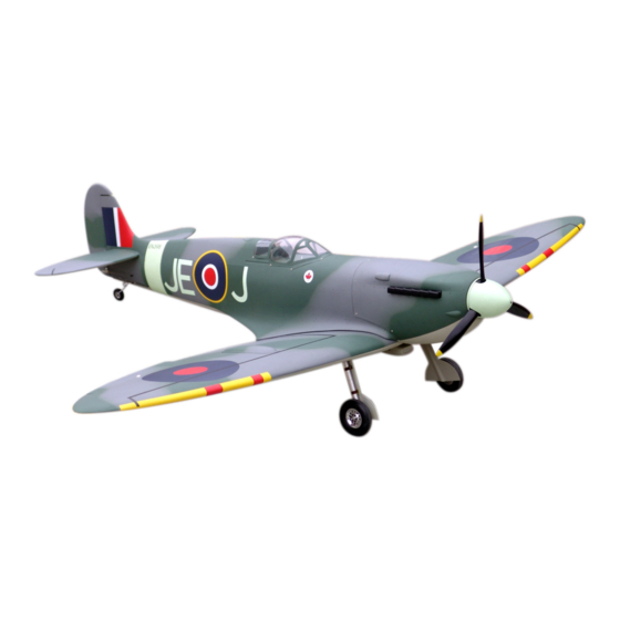
50cc SPITFIRE
Strut
Specifications:
Length:
1935mm(76.2")
Wing span:
2260mm(89")
Wing area:
93sq.dm(10sq.ft)
Wing loading: 108.6g/sq.dm(35.6oz/sq.ft)
Flying weight: 10.1kg(22.2lbs)
Radio:
6ch & 8servos
Engine:
50cc gas engine
SAFETY PRECAUTIONS
INSTRUCTION MANUAL
This R/C airplane is not a toy!
(The people under 18 years old is forbidden from flying this model)
First-time builders should seek advice from people having building
experience.If misused or abused,it can cause serious bodily injury
and damage to property.
Fly only in open areas and preferably at a dedicated R/C flying site.
We suggest having a qualified instructor carefully inspect your
airplane before its first flight.Please carefully read and follow all
instructions included with this airplane,your radio control system
and any other components purchased separately.
Advertisement
Table of Contents

Subscribe to Our Youtube Channel
Related Manuals for Troy Built Models 50cc SPITFIRE


Summary of Contents for Troy Built Models 50cc SPITFIRE
- Page 1 Adjustment. The centre of the Gravity. 50cc SPITFIRE Side View RUDDER 40mm 40mm 153mm Top view Two wheel retract system Make sure to assemble retracts as instructed below. 3-way pressure inlet 3-way Strut pressure inlet Strut Air inlet 3-way Air tank...
- Page 2 Epoxy the fiber deconations to aprropriate position Epoxy the landing gear to the wing steadily. on the bottom of the wing. Gasoline tube 210mm Gasoline 195mm 6 channel radio for aiplane is highly recommended for this model. Accessory list for the coming installation steps. Adjustment.
- Page 3 Epoxy plies to relevant position inside the fuselage as Disassemble the wing and set the ply to the slot Assemble the aileron to main wing with instant type AB glue. Be careful Accessory list for the coming installation steps. below for assembling the cowling. in the wing root.
- Page 4 The sketch map should be when the stabilizer Keep some space about 1mm width between Accessory list for the coming installation steps. Secure the servo.Install the nylon control horn assembly completion. trailing edge and flap. and connect the linkage. Make sure to glue securely. Canopy TP Screw (2.3x12mm) If not properly glued, a failure in flight may occur.
- Page 5 Drill a small hole to appropriate possition in the Mount the gear door and the wheel to the retract. Install the servo. Install the nylon control horn and connect the linkage. fuselage for installing the plastical tube. Collar (3mm) Washer(2x5mm) LockNut(4mm) Screw (2x10mm) Bushing (8X4mm)
- Page 6 Assemble the wheel mount to the thick wooden block Trim the sheet carefully from the wing for assembling According to the rib template drill a hole to one wing Drill holes to appropriate position in the rudder and epoxy with screw,cut the surplus parts and epoxy the thinner the wheel well,epoxy the wheel well to it.
- Page 7 The sketch map should be when the stabilizer Mount the fuel tank to the fuselage. Accessory list for the coming installation steps. Assemble the servos. assembly completion. Make sure to glue securely. TP Screw (2.3x12mm) Set screw (3x4mm) If not properly glued, a failure in flight may occur. Securely glue together.If coming off during flights, U-style wire (130x25x3mm) you'll lose control of your airplane which leads...
- Page 8 Keep some space about 1mm width between Fix the elevator servo to appropriate position The side view when the engine installation finished,the steps should be assemble Set the U-style wire through the enlarged hole as below. the engine to engine mount after step 36 &37,adjust the engine mount to a proper elevator and tailing edge.
Need help?
Do you have a question about the 50cc SPITFIRE and is the answer not in the manual?
Questions and answers