
Subscribe to Our Youtube Channel
Related Manuals for MIMAKI JF-1631


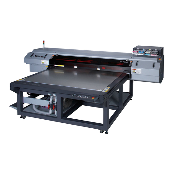
Summary of Contents for MIMAKI JF-1631
- Page 1 MIMAKI ENGINEERING CO., LTD. TKB Gotenyama Building, 5-9-41, Kitashinagawa, Shinagawa-ku, Tokyo 141-0001, Japan Phone: +81-3-5420-8671 Fax: +81-3-5420-8687 D201645-20 URL: http: // www.mimaki. co. jp/...
-
Page 2: Table Of Contents
Installing the device ..........1-2 Where to install the device ........1-2 Configuration and Function ........1-3 Front Side ..............1-3 Rear Side ..............1-3 Operation Panel (JF-1631) ........1-4 Operation Panel (JF-1610) ........1-5 Carriage ..............1-6 Capping Station ............1-6 Flushing BOX ............1-6 EMERGENCY SWITCH ..........1-7 Connecting the cables .......... - Page 3 Turning the power ON ..........2-4 Setting the media ........... 2-5 Setting the media on JF-1610 ........2-5 Setting the media on JF-1631 ........2-6 Using of Roll Sheet ........... 2-8 Test drawing ............2-9 Execution of test drawing ......... 2-9 Execution of head cleaning ........
- Page 4 Other useful settings ..........3-17 Initializing set contents ..........3-18 For setting media correctly ........3-19 CHAPTER 4 Daily Maintenance Routine maintenance ..........4-2 When the device is left unused for a long period of time ...............4-2 Notes on cleaning .............4-2 Maintenance of frame component ......4-3 Ink cartridge ............
- Page 5 Checking UV ink curing level ....... 4-41 Adjusting UV light level ........... 4-42 Checking method of UV illumination intensity ..4-43 Check the UV illumination intensity ......4-44 CHAPTER 5 In Case of Trouble Before taking a phenomenon as a trouble ..... 5-2 The device cannot be energized ......
-
Page 6: Caution
• In the case where MIMAKI-recommended cable is not used for connection of this device, limits provided by FCC rules can be exceeded. To prevent this, use of MIMAKI-recommended cable is essential for the connection of this device. -
Page 7: Laser Safety
CAUTION LASER SAFETY This Model is certified as a Class II laser product under the U.S. Department of Health and Human Services Radiation Performance standard according to the Radiation Control for Health and Safety Act of 1968. This means that this Model does not produce hazardous laser radiation. CDRH REGULATION The Center for Devices and Radiological Health for the U.S. -
Page 8: Foreword
Before starting to operate the printer, be sure to read this Operation Manual carefully . On this operation manual • This Operation Manual describes the operation and maintenance of Model JF-1631/1610 Color Ink Jet Printer (hereinafter referred to as the device). -
Page 9: Features
As the ultraviolet curing device (UV lamp) is mounted, ink curing fixation of ink after printing is allowed. Wide printing width Wide printing width is realized. JF-1631 :1602mm (63 inch) × 3100mm (122 inch) JF-1610 :1602 mm(63inch)x1016mm(40inch) Printing on media having thickness up to 50mm This machine can print on media having thickness up to 50mm. -
Page 10: For Safe Operation
For safe operation Pictorial signs Pictorial signs are used in this Operation Manual for safe operation of and in prevention of damages to the device. Pictorial signs and their meanings are given below. Read and fully understand before reading the text. - Page 11 For safe operation WARNING • Be sure to setup the appropriate air-moving system in case of using the device in a closed room or a room with bad ventilation. Cautions for constructing exhaust outlet Please observe the following things to prevent the device. (1) The sharp of the exhaust outlet depends on your building enviroment.
- Page 12 Never do the following WARNING Do not disassemble or remodel the device Handling of ink cartridges • Never disassemble or remodel the main • Some of the ingredients (UV Curing unit printer initiator) have toxic consequences to cartridge.Disassembling/remodeling any of aquatic life.Avoid leak into water system or them will result in electric shocks or sewage containing water.
- Page 13 • Be sure to use only the UV lamp • Use the unit under the power specifications recommended by Mimaki,or it may cause given.Be sure to connect the power cable fire or damages to the unit.Never use UV...
-
Page 14: Precautions For Use
Handling the Anti-freezing liquid • Use the exclusive Anti-freezing liquid by • If you swallowed the Anti-freezing liquid or Mimaki ,or the heater may be damaged. mixed soft water with antifreezing liquid • If the Anti-freezing liquid or mixed soft... - Page 15 For safe operation CAUTION Ink cartridges • If the ink cartridge is moved from a cold • You cannot use any other ink type than the place to a warm place, leave it in the room exclusive one. If you use any other ink temperature for three hours or more before type, it may cause the damage for the using it.
- Page 16 UV devices other the UV ink curing level is significantly than those recommended by Mimaki.We lowered.If the UV lamp or silica glass is would take no responsibility for any...
- Page 17 For safe operation Notices for installation CAUTION A place exposed to direct A place that is not horizontal A place in which temperature sunlight and humidity vary by a great margin • Use the device under the following environment. Operating •...
-
Page 18: How To Read This Operation Manual
How to Read This Operation Manual This manual provides the explanation about the displayed characters and used keys on the “Display Panel” in addition to the operation procedures. Proceed operations confirming them while using. xvii... - Page 19 Where to install the device ........1-2 Configuration and Function ......... 1-3 Front Side ..............1-3 Rear Side ..............1-3 Operation Panel (JF-1631) ........1-4 Operation Panel (JF-1610) ........1-5 Carriage ..............1-6 Capping Station ............1-6 Flushing BOX ............1-6 EMERGENCY SWITCH ..........
-
Page 20: Installing The Device
Secure sufficient space for installation before assembling this unit. Decide the place considering the size of the device and a space required for execution of drawing. Machine Type Width Depth Height Total Weight JF-1631 3430 mm 4250 mm (Min.) 1385 to (Max.) 1465mm Approx.1150 kg JF-1610 3430 mm 2005 mm (Min.) 1385 to (Max.) 1465mm... -
Page 21: Configuration And Function
Configuration and Function Front Side Indicator Ink station Indicating a state of the machine. Insert ink cartridges here. P.1-10) P.1-9) ( Carriage ( P.1-6) Table Setting media on it. ( P.2-5) There are absorbing holes on the table so that media is absorbed when vacuum is ON. -
Page 22: Operation Panel (Jf-1631)
Operation Panel (JF-1631) The operation panel is used for setting of drawing method and each operation. POWER Lamp Key ( P.2-5) VACUUM/BLOW Lit when the power is ON. Switching VACUUM to BLOW, and vice versa. TEST VACUUM Lamp ( P.2-5) Press to start the test drawing. -
Page 23: Operation Panel (Jf-1610)
Configuration and Function Operation Panel (JF-1610) POWER Lamp Key ( P.2-5) VACUUM/BLOW Lit when the power is ON. Switching VACUUM to BLOW, and vice versa. TEST VACUUM Lamp ( P.2-5) Press to start the test drawing. Lit when media is set. P.2-9) BLOW Lamp ( P.2-12) -
Page 24: Carriage
Carriage A print head for drawing, a UV irradiation appliance, and a light pointer in the print head cover are mounted on the carriage. Depending on UV lamp condition, the carriage is positioned differently. Capping Station The capping station on the front-right side of the unit consists of the ink caps and suction nozzle used for the maintenance of the print head. -
Page 25: Emergency Switch
Configuration and Function EMERGENCY SWITCH One EMERGENCY switch is placed on the front face of the unit and 2 are placed on each of the buck surface and Y-bar respectively. When stopping the machine for safety reason, press the switch. -
Page 26: Connecting The Cables
Connecting the cables Connecting the USB2.0 interface cable Connect a computer to this machine with the USB2.0 interface cable. • Your RIP is required to support USB2.0 interface. • If USB2.0 interface is not installed in your computer, ask a RIP maker near you or our branch office. -
Page 27: Uv Irradiation Device And Indicator
UV irradiation device and Indicator UV irradiation device • Do not expose your naked eyes directly to the light irradiated from the UV lamp when it lights. Orange • Do not touch the lamp when it is being lit or just after it is Green set OFF. -
Page 28: Setting Of Ink Cartridge
Setting of ink cartridge Use ink cartridge inserting it into the ink station. Kinds of ink that can be used Kind of ink Color Product Number Magenta SPC-0371M Cyan SPC-0371C Yellow SPC-0404HY Black SPC-0371K-2 UV Ink Light cyan SPC-0371Lc Light magenta SPC-0371Lm White SPC-0371W-5... - Page 29 • Never disassemble the ink cartridge. • Never refill the ink cartridge with ink. Refilling the ink cartridge can cause a trouble. Remember that Mimaki assumes no responsibility for any damage caused by the use of the ink cartridge replenished with ink.
-
Page 30: About Media
About Media The sizes of media that can be used and the method of handling are described here. The sizes of media that can be used JF-1631 JF-1610 Maximum width 1694 mm Maximum length 3194 mm 1080 mm Max. drawing width 1602 mm Max. -
Page 31: Menu Mode
Menu mode This device has three modes. Each mode is described below. Local Mode Local mode is a mode in drawing preparation state. All keys are available. Receiving of data from the computer is allowed, however, drawing is not executed. The following operations are allowed in the local mode. - Page 32 1-14...
- Page 33 Operation flow ............2-3 Turning the power ON........... 2-4 Setting the media........... 2-5 Setting the media on JF-1610 ........2-5 Setting the media on JF-1631 ........2-6 Using of Roll Sheet ............ 2-8 Test drawing ............2-9 Execution of test drawing .......... 2-9 Execution of head cleaning ........
-
Page 34: How To Use The Opening/Closing Door
How to use the opening/closing door Close the door while performing the drawing to avoid the bad effect to be caused by UV lamp. When setting the media Set the media after opening the door. • When setting the media, avoid contact of the media to the door. -
Page 35: Operation Flow
Operation flow Turning the power ON See "Turning the power ON" P.2-4) Setting the media See "Setting the media" ( P.2-5) Test drawing See "Test drawing" ( P.2-9) Execution of head See "Execution of head cleaning" P.2-10) cleaning Drawing an image from See "Drawing an image from source data"... -
Page 36: Turning The Power On
Turning the power ON • When the power is turned ON, the Y-bar moves. To avoid injuries, keep your hands away from the table. • If the temperature in the hot water device has not reached the predetermined value, a message is indicated. -
Page 37: Setting The Media
Setting the media • If, within the absorption area, there are suction holes not closed by the media, close such suction holes placing thin sheet form material such as paper, film or tape. • The peripheral parts of the media could roll up due to heat. Fix the media supplementarily using adhesive tapes, etc. -
Page 38: Setting The Media On Jf-1631
Setting the media on JF-1631 Switch over the suction valve at the front of the table adjusting with the size of the media to be set. • The valve is opened when the knob is turned vertically and closed when it is turned horizontally. - Page 39 Setting the media On the absorption area The absorption area of JF-1631 is shown in the following figure. Pressing key, set the FRONT REAR optimum absorption area for the media to be set. ▲ Mark Use as a rough guide for valve opening and closing.
-
Page 40: Using Of Roll Sheet
Setting the media Using of Roll Sheet Set the roll sheet on the roll sheet hunger on the back face of this device. -
Page 41: Test Drawing
Test drawing Make test drawing to check whether there is nozzle clogging or other drawing failures (such as wearing or missing). Execution of test drawing • Printing is disabled when the following messages are displayed. It is enabled when the message has disappeared. -
Page 42: Execution Of Head Cleaning
Execution of head cleaning When a correct pattern is not obtained in the test drawing, perform the head-cleaning. As for the head cleaning, the following 3 types are available. To be used if ten odd numbers of the lines are missing when the test pattern is normal P.2-10 made. -
Page 43: When Cleaning With "Wiping
Execution of head cleaning When cleaning with “Wiping” Press the key in the local CLEANING C L E A N I NG mode. T Y P E : n o r m a l Select wiping with keys C L E A N I NG and press key. -
Page 44: Drawing An Image From Source Data
Drawing an image from source data Starting the drawing operation • If the UV irradiation device is not ready or the temperature of the water heating system has not reached the predetermined value, a message is displayed. Drawing is not allowed in such cases. -
Page 45: Interruption Of Drawing
Drawing an image from source data Interruption of drawing To interrupt the drawing, stop the drawing operation and erase the received data from the device. Press the key while drawing. REMOTE < L OC A L > 2 . 5 mm •... - Page 46 Drawing an image from source data Set the moving position by pressing V I EW keys. P O S I T I ON 5 0 0 MM • If you press key, the Y-bar will move to the back of the table centering the origin of the drawing.
-
Page 47: Turning The Power Off
Turning the power OFF To turn off, check first whether or not there is data received and there remains data that has not yet been output in the device. Turn the power of the connected computer off. Press the power button to cut the power. •... - Page 48 2-16...
- Page 49 CHAPTER 3 Useful Function This chapter describes the setting procedures of each functions, and how to operate the plotter usefully. Changing origin ............. 3-2 Changing origin with JOG keys ......... 3-2 Changing origin with FUNCTION menu ....3-3 Registering the thickness of the media....3-4 Register the thickness of the media manually ...
-
Page 50: Changing Origin
Changing origin The default origin position can be changed. There are following 2 changing methods. Changing with the JOG keys Changing with the “ORIGIN” in the FUNCTION menu Changing origin with JOG keys Press the keys OR I G I N S E T U P in the local mode. -
Page 51: Changing Origin With Function Menu
Changing origin Changing origin with FUNCTION menu To precisely set the origin of coordinates, set its X- and Y- coordinates from the FUNCTION menu. This setting value becomes the origin position (0, 0). Press the key in the local FUNCTION F UN C T I ON mode. -
Page 52: Registering The Thickness Of The Media
Registering the thickness of the media Register the thickness of loading media. There are two ways to register the thickness, one is to register manually and the other is to measure the thickness automatically. Register the thickness of the media manually Press the key in the local FUNCTION... -
Page 53: Measuring The Thickness Of The Media Automatically
Registering the thickness of the media Measuring the thickness of the media automatically Press the key in the local FUNCTION F UN C T I ON mode. V I EW < E N T > Select the [HEAD HEIGHT] by pressing F UN C T I ON key. -
Page 54: Adjusting Head Gap
Adjusting head gap The value of gap between the head and the media is adjusted. There are 2 setting methods, namely a method of selecting with keys and a method of setting in the “HEADGAP” of the FUNCTION menu. Adjust head gap with the keys DOWN Press the... -
Page 55: Registering Head Gap Value
Adjusting head gap Registering Head gap value Inputting the value of gap between the head and the media The registered value is reflected on all media. Press the key in the local FUNCTION F UN C T I ON mode. V I EW <... -
Page 56: Turing The Uv Lamp Off
Turing the UV lamp off The UV lamp is turned off automatically in 30 minutes after finishing the drawing (default). If turning off of the UV lamp immediately is required, execute the following operation. Press the key in the local FUNCTION F UN C T I ON mode. -
Page 57: Other Useful Functions
Other useful functions Data clear Erase the data not required for this device with the following operation. Press the key in the local DATACLEAR D A T A C L E A R mode. < E N T > Press the key. -
Page 58: Each Setting
Each setting Setting the print method Settings on printing Press the key in the local FUNCTION F UN C T I ON mode. V I EW < E N T > Select the [SET UP] by pressing F UN C T I ON key. - Page 59 Each setting Item Value Outline STANDARD Standard drawing quality QUALITY FINE High quality drawing (drawing speed is slower) FAST High speed drawing (quality is inferior) Drawing is conducted in both directions when the head moves on the BI-DIR media at drawing. (Quicker drawing compared to “UNI-DIRN”...
-
Page 60: Setting The Light Intensity Of The Uv Lamp
Setting the light intensity of the UV lamp The light intensity of the UV lamp may be set in 3 stages. This setting is made when the media vulnerable to the heat is used or when the test drawing is made in which the lighting of the UV lamps is not desired. -
Page 61: Setting Of Priority
Each setting Setting of priority Priority of setting of this device or that of the computer on the following items respectively is selected. Items to be selected:Drawing type/ Over-painting Press the key in the local FUNCTION F UN C T I ON mode. -
Page 62: Changing Language Display On The Screen
Changing language display on the screen Display language can be selected between Japanese and English. Press the key in the local FUNCTION F UN C T I ON mode. V I EW < E N T > Select the [DISPLAY] by pressing the F UN C T I ON key. -
Page 63: Output The Setting List
Each setting Output the setting list Keep the list for customer’s record or send it by the fax at inquiry on the maintenance. Set a larger media than the legal size. P.2-5) ( Press the key in the local FUNCTION F UN C T I ON mode. -
Page 64: Displaying Machine Information Of This Device
Displaying machine information of this device Press the key in the local FUNCTION F UN C T I ON mode. V I EW < E N T > Select the [MAINTENANCE] by F UN C T I ON pressing the key. -
Page 65: Other Useful Settings
Each setting Other useful settings Change settings according to need. Press the key in the local FUNCTION F UN C T I ON mode. V I EW < E N T > Select the [SET UP] by pressing the F UN C T I ON key. -
Page 66: Initializing Set Contents
Each setting Initializing set contents Press the key in the local FUNCTION F UN C T I ON mode. V I EW < E N T > Select the [SET UP] by pressing the F UN C T I ON key. -
Page 67: For Setting Media Correctly
For setting media correctly Guide holes for inserting commercial screws are placed on each end (3 sides) of the table. • Fix a guide for placing the media on the correct position using those holes. • For JF-1610, the guide holes are not arranged in the front side. - Page 68 3-20...
- Page 69 CHAPTER 4 Daily Maintenance Items required for using this unit conveniently, such as an ink replacing method or a cleaning manner, are described. Routine maintenance......4-2 In case defective printing is not When the device is left unused for a resolved ...........
-
Page 70: Routine Maintenance
Routine maintenance Be sure to conduct maintenance works for the device depending on operation frequency or periodically so as to use the device for a long time while keeping its drawing accuracy. When the device is left unused for a long period of time •... -
Page 71: Maintenance Of Frame Component
Routine maintenance Maintenance of frame component If the frame components of the device have stained, dampen a poece of soft cloth with water or neutral detergent diluted with water, squeeze it and wipe the frame components clean. -
Page 72: Ink Cartridge
Ink cartridge Replacing with a new ink cartridge Replacing of ink cartridges is required in the following cases. Display on the screen Outline Remaining amount of ink in an ink cartridge is few. < L OC A L > • Drawing can be continued, but running out of ink may occur during the drawing. I N K N E A R E ND : M _ _ _ _ _ _ Earlier replacement is recommended. -
Page 73: Ink Cartridge Trouble
Ink cartridge Ink cartridge trouble When an ink cartridge trouble is detected, a warning message appears and printing, cleaning and all other activities that use ink are deactivated. In this case, replace the ink cartridge in question immediately. • Do not leave the ink cartridge unreplaced for a long time as this will cause the nozzle clogging and the printer must be repaired by a service person. -
Page 74: Cleaning Flushing Box
Cleaning flushing BOX Replacing waste ink absorption material in the flushing BOX. Contents of the • Maintenance cleaning liquid (SPC-0385) cleaning kit • Gloves • Paper towel • Goggles • When conducting the replacing, be sure to wear the supplied goggle and gloves since you may get ink in your eyes. - Page 75 Cleaning flushing BOX eplace the absorption material inside the flushing BOX. Replace the absorption material inside the flushing BOX on the left side.
-
Page 76: Avoiding Dripping Of Ink Droplet At Printing
Avoiding dripping of ink droplet at printing Cleaning of the head guard plate Ink droplets caused by drawing may appear on a head guard plate on a bottom face of the carriage. As they can cause stain on media by dripping of ink droplets or drawing trouble, conduct cleaning of the bottom face of the carriage periodically. - Page 77 Avoiding dripping of ink droplet at printing Press the key. ENTER MA I N T E N A N C E S T A T I ON < e n t > Press the key. ENTER S T A T I ON ME N T : C A RR I A G E o u t Press the key.
-
Page 78: When The Waste Ink Is Pooled Up
When the waste ink is pooled up Waste ink used for cleaning the heads will gather in the waste ink tank. • Contact the local dealer or call our branch if you need a spare waste ink tank. • Prepare a polyethylene tank for emptying waste tank. •... -
Page 79: Disposing Of The Ink In The Wiper Tank
When the waste ink is pooled up Disposing of the ink in the wiper tank Screw Open the waste ink box cover. (1) Remove the screws fixing the both sides of the waste ink BOX cover. (2) Open the cover. Waste ink box cover Remove the wiper tank and discard the... -
Page 80: Replacing The Filter Of The Cooling Fan
Replacing the filter of the cooling fan Replace the filter of the cooling fan periodically. (Once around a month) • When replacing, be sure to wear the supplied goggles and gloves since you may get ink in your eyes. • Alcohol •... - Page 81 Replacing the filter of the cooling fan Remove screws (4 pieces) of the filter Assy. Replace the filtering element. • Prepare the new filtering element and replace with filtering element Return the filter Assy to the original state. Attach the filter Assy to the cooling fan and tighten the screws of the upper Finger part.
-
Page 82: Cleaning Nozzle Face Automatically
Cleaning nozzle face automatically When predetermined times of printing is completed, nozzle face of the head is cleaned automatically to remove ink droplets stuck to the nozzle face. Select the “PERIODICAL WIPING MODE” of the maintenance menu. (1) Press the key in the local mode. -
Page 83: When Media Thickness Is Changed
When media thickness is changed Adjust the ink drop position in drawing by the following operations so as to obtain proper drawing performance when the media thickness is changed in use. Samples of pattern drawn Set a media and the home position for drawing. •... - Page 84 When media thickness is changed Check the position where the drawn pattern is in one straight line. • In the case of the figure in the right, you will notice that a straight line is formed at the point +140. Adjust it by pressing P RN .
-
Page 85: Changing The Ink Set
Changing the ink set The standard ink set of this machine consists of 4 colors (Magenta, Cyan, Yellow, Black) and is changeable to the following ink sets according to user’s purpose Available Ink Sets Ink slot No. The number of colors (Magenta) (Cyan) (Yellow) - Page 86 Changing the ink set Ink set changing procedures are described below. Example) : When “4 colors ink set” is changed to “6 colors ink set”, Select the “INKSET MODE” of the maintenance menu. (1) Press the key in the local mode. FUNCTION (2) Select the [MAINTENANCE] by pressing key, and press the...
- Page 87 Changing the ink set Set the ink color cartridge indicated on I N K S E T : * * * * m c * * the display when the display shown on S E T C A R T R I DG E the right is indicated.
-
Page 88: In Case Defective Printing Is Not Resolved
In case defective printing is not resolved When the image quality is not improved after repeated head cleanings, perform the filling of the ink. Filling the ink Insert the ink cartridge in the ink station. • Set the ink cartridge securely. Press the key in the local FUNCTION... - Page 89 In case defective printing is not resolved Press the key. ENTER F I L L U P * - - - - - - - - - - - - - - - - - - - • Filling of the ink will start. •...
-
Page 90: Regular Maintenance For White Ink
Regular maintenance for white ink White ink is easier precipitate than other inks. • In case without printing more than two weeks, white ink may cause precipitate in ink cartridge or inside of the device. • When the ink is precipitated, nozzle clogging occurs and normal drawing can not be obtained. •... - Page 91 Regular maintenance for white ink When a screen shown in the right is WH I T E MA N T displayed,Return the white cartridge to S E T C A R T R I DG E the ink station. • As shown in the drawing, set an ink cartridge turning up a side containing the IC chip.
-
Page 92: Head Maintenance Function
Head maintenance function With the use of the head maintenance function, when the power supply is put ON, the head cleaning and wiping will be performed automatically to prevent the media from being stained. • After putting ON the power supply and when the head reaches the set temperature, the cleaning/wiping operation will be performed. -
Page 93: Special Refresh
Special refresh Set the head frequently to refresh by the following operations when refreshing is required frequently due to drawing failures (blurring or missing) on the data drawn. Select the “SP.REFRESH MODE” of the maintenance menu. (1) Press the key in the local mode. FUNCTION (2) Select the [MAINTENANCE] by pressing key, and press the... -
Page 94: Cleaning Of Wiper And Cap
Cleaning of wiper and cap A cap prevents a nozzle from clogging caused by drying. A wiper sweep ink stuck to a nozzle of the head. The wiper or the cap becomes tainted with ink or dusts during the operation of the device. In order to maintain good condition of the heads, clean the wipers and caps frequently. - Page 95 Cleaning of wiper and cap Remove ink stuck to the wiper and the bracket with the exclusive cleaning swab soaked in the cleaning liquid. • If stain or bent of the wiper is too severe, replace the wiper with new one. Conduct replacing follow the wiper replacement procedure, after completing this operation.
- Page 96 Cleaning of wiper and cap Attach the suction nozzle Assy pressing it firmly under the suction nozzle. • The wiper M will stick out by around 0.5 mm after being attached. Wipe off the ink and others stuck to the cap with nonwoven cloth.
-
Page 97: Replacing Water In Water Heater Tank
Precautions in handling the antifreeze liquid • Be sure to wear goggle and gloves for handling the antifreeze liquid. • Use the recommended antifreeze liquid by Mimaki. (Antifreeze liquid for replacement: SPC- 0394 [1000cc X 2 pieces]) • Do not touch the antifreeze liquid directly. If the antifreeze liquid settles on the skin or clothes, immediately wash it off with soap and water. -
Page 98: Replacement Method Of Antifreeze Liquid Water
Replacement method of antifreeze liquid water There are following two methods for changing the antifreeze liquid mixed water: Make replacement using hot The antifreeze liquid mixed water inside the piping can also be water exchange mode on the discharged completely. Further, this work is performed safely, as it may maintenance menu. - Page 99 Replacing water in water heater tank Lift the water heating system and engage the hanger with the hook. Remove the hot water tank. • Move the remaining antifreeze liquid into a polyethylene tank. • Take care not to spill the antifreeze fluid. If spilled, be sure to wipe it off immediately.
- Page 100 Replacing water in water heater tank Press the key. ENTER WA T E R CHNG S E T A F : e n t Press the key twice to finish. Replacing when the power is turned OFF Make sure that the power supply is turned OFF and remove the blue colored socket.
-
Page 101: Replacing Exhaust Blower
Replacing exhaust blower Using exhaust blower, the heat generated at the time of making drawings is exhausted. The ink mist sucked in at such time will be hardened and disturb the normal operation of the exhaust blower. Replace the exhaust blower in the following situations: When the exhaust blower does not function normally “ERROR706 UV1 overheat”... - Page 102 Replacing exhaust blower Remove the connecting cable of the exhaust blower from the clamps. Remove the exhaust blower. • Remove the screws (2 pieces), and take out the exhaust blower. Fix the new exhaust blower. • Tighten the screws (2 pieces) to fix the exhaust blower.
-
Page 103: Setting The Uv Lamp Off Duration
Setting the UV lamp OFF duration Select the “UV LAMP MODE” of the maintenance menu. (1) Press the key in the local mode. FUNCTION (2) Select the [MAINTENANCE] by pressing the key, and press the key. ENTER (3) Select the [UV LAMP] by pressing the key. -
Page 104: Cleaning Of Uv Lamp Filter
Cleaning of UV lamp filter To use for a long time, clean the UV lamp filter periodically (once around two weeks). • When cleaning, be sure to wear the supplied goggles and gloves since you may get ink in your eyes. - Page 105 Cleaning of UV lamp filter Remove the filter holder. Filter holder Remove the mesh filter. • The mesh filter is under the UV lamp connector cover. Remove it while pulling the filter. Mesh filter UV lamp connector cover Clean the mesh filter. •...
-
Page 106: Replacing Uv Lamp
Replacing UV lamp The UV lamp is a consumable parts. This units counts the duration of irradiation with the UV lamp to notify the replacing timing. Checking UV lamp irradiation duration Press the key several times in ENTER < L OC A L > the local mode. - Page 107 Replacing UV lamp Pull out the exhaust blower Assy upward. Pull out • After removing the finger screws on the top part of the exhaust blower Assy, pull out the exhaust blower Assy. Exhaust blower Assy Remove UV lamp cassette. Remove (1) Remove the bolt on the front of the UV lamp cassette using supplied hexagonal wrench.
-
Page 108: Resetting Uv Lamp Irradiation Duration
Replacing UV lamp Resetting UV lamp irradiation duration After replacing the UV lamp, reset the irradiation duration stored in this unit. Select the “UV LAMP MODE” of the maintenance menu. (1) Press the key in the local mode. FUNCTION (2) Select the [MAINTENANCE] by pressing the key, and press the key. -
Page 109: Checking Uv Ink Curing Level
Checking UV ink curing level As the UV lamp is deteriorated, the ink curing level may be lowered. Check the UV ink curing level and adjust the UV lamp light intensity, if necessary. Set media for drawing patterning on the table. •... -
Page 110: Adjusting Uv Light Level
Checking UV ink curing level Press the key. ENTER T E S T D R AW * * • Test drawing starts. Check the drawing pattern after completion of the drawing. • If the UV light intensity goes lower, good drawing pattern cannot be obtained. In this case execute the operation of “Adjusting UV light level”. -
Page 111: Checking Method Of Uv Illumination Intensity
Checking method of UV illumination intensity UV lamp is a consumable. The more the irradiation time increases, the more the amount of light decreases and the ink will become hard to harden. When the cumulative irradiation time exceeds a certain value, a message prompting you for checking the illumination intensity is displayed on the operation panel. -
Page 112: Check The Uv Illumination Intensity
Check the UV illumination intensity Mount the sensor part of the illumination meter on the illumination meter bracket. (1) Turn over the illumination meter bracket and insert the sensor into the guide part. • Set it with the sensor hole faces downward so that the hole can be seen from the obverse side of the bracket. - Page 113 Checking method of UV illumination intensity Mount the illumination meter bracket on the device. (1) Place the illumination meter bracket and the illumination meter on the left rear of the table. • Adjust the rabbet for positioning the illumination meter bracket in order to match to the corner of the adsorption board.
- Page 114 Checking method of UV illumination intensity Remove the illumination meter bracket from the device. • The illumination meter bracket is heated by the UV lamp immediately after checking the illumination intensity and if you touch it, you may suffer burns. Remove the illumination meter bracket after being cooled fully.
- Page 115 CHAPTER 5 In Case of Trouble This chapter describes the actions to be taken when the plotter develops any trouble or displays an error message. Before taking a phenomenon as a trouble..5-2 The device cannot be energized ....... 5-2 The device cannot perform printing ......
-
Page 116: Before Taking A Phenomenon As A Trouble
Before taking a phenomenon as a trouble If something is wrong with the device, the buzzer sounds and a corresponding error message is given on the LCD. Take an appropriate corrective measure in accordance with the message. The device cannot be energized More often than not, this is due to improper connection of the power cable. -
Page 117: If Image Quality Declines
Corrective measures against troubles in the case where satisfactory image quality is not provided are described in this station. Take measures in accordance with actual state of the picture. If the measures fail restore the device to the normal state, contact your local MIMAKI distributor or MIMAKI office call for service. Development... -
Page 118: Troubles For Which Error Messages Are Given On The Lcd
: MC Y K K Y CM previous one. The loaded ink cartridge is not • Use the ink specified by MIMAKI. < L O C A L > MIMAKI genuine. N O N - O R I G N L : MC Y K K Y CM •... -
Page 119: Error Message
If any error message is given on the LCD, turn off the power to the device and turn it on after a while. If the same error message appears again on the LCD, contact your local MIMAKI distributor or MIMAKI office to call for service. - Page 120 Error message Cause Corrective measure • Turn off the power to the device an E R R O R 4 0 1 The X motor has been overload. turn it on after a while. MO T O R X • If the same error message appears again on the LCD, contact your local E R R O R 4 0 2 The Y motor has been overload.
- Page 121 Troubles for which error messages are given on the LCD Error message Cause Corrective measure • Conduct cap cleaning with reference The time for cleaning the E R R O R 6 0 7 to P.4-26. capping has come. C A P C L E A N I N G •...
- Page 122 Troubles for which error messages are given on the LCD Error message Cause Corrective measure • Execute ink filling. ( P.2-4 ) E R R O R 9 0 1 Certain ink is not filled. N O T C OM P L E T E F U P •...
- Page 123 CHAPTER 6 Appendix Tables of specifications and functions of this unit are described. Specifications ............6-2 Basic unit specifications ..........6-2 Specifications for ink ..........6-3 Position of the warning label........ 6-4 Function Flowchart ..........6-7...
-
Page 124: Specifications
UV unit Bottle type (200cc/, with tank full sensor) Waste ink tank USB2.0 compliance Interface MRL-II B Command <ESC/P Level 2 base, MIMAKI original command> Less than 55dB Stand-by (FAST-A, 1m in all direction) Operation continuous Noise Less than 65 dB... -
Page 125: Specifications For Ink
Specifications Specifications for ink As for the detail, ask the dealer or our branch. Item Parts No./ Specification Exclusive UV ink cartridge Feature Black, magenta, cyan, yellow, light cyan, light magenta, Ink type white , Clear coat 440CC Capacity of ink cartridge One year from the date of manufacture Shelf life During storage... -
Page 126: Position Of The Warning Label
Position of the warning label This device is adhered with the warning label. Be sure to fully understand the warning given on the labels. In the case where any of the warning label has become so soiled that the warning message is illegible or has come off, purchase a new one from your local distributor or our office. - Page 127 Position of the warning label No. Reorder No. Lavel No. Reorder No. Lavel M903330 M903763 M903747 M904131 M904148 M903764 LHCM-02 PEC-02 M904130 M902396 M905491 M963239 M905490 M901549 M905122 M905265 M903946...
-
Page 129: Function Flowchart
Function Flowchart TEST key < L OCA L > T E S T DRAW * * T E S T DRAW * * 2 . 5 mm NOZ Z L E CHK < EN T > T E S T DRAW HARDEN CHK <... - Page 130 < L OCA L > F UNC T I ON V I EW 2 . 5 mm V I EW < EN T > S T AR T < e n t > V I EW S E T V I EW POS <...
- Page 131 Function Flowchart MOV I NG NOW P L E A S E WA I T V I EW POS I T I ON : * * * * MM MED I A T H I CKNE S S MED I A T H I CKNE S S 2 .
- Page 132 Followed Followed S E T UP I NK L A Y ERS < e n t > S E T UP UV L E V E L < e n t > S E T UP PR I OR I T Y <...
- Page 133 Function Flowchart S E T UP I NK L A Y ERS 1 to 9 S E T UP UV L E V E L : H I GH HIGH , STANDRD , LOW, NONE , NOPRINT S E T UP S E T UP PR I N T MODE : HOS T...
- Page 134 Followed Followed MA I N T ENANCE I N T . W I P I NG < e n t > MA I N T ENANCE PRN . a d j u s t < e n t > MA I N T ENANCE I NK S E T <...
- Page 135 Function Flowchart I N T . W I P I NG PR I N T COUN T = 1 0 OFF , 1 to 100 PRN . a d j u s t PRN . a d j u s t PRN .
- Page 136 Followed Followed MA I N T ENANCE S P . RE F RE SH < e n t > MA I N T ENANCE UV L AMP < e n t > MA I N T ENANCE WA T ER CHNG <...
- Page 137 Function Flowchart S P EC I A L RE F RE SH HE AD [ _ _ _ _ _ _ W_ ] UV L AMP L E V E L CHECK L E V E L CHECK L E V E L CHECK <...
- Page 138 Followed Followed MA I N T ENANCE L I S T < e n t > MA I N T ENANCE I N FOMA T I ON < e n t > MA I N T ENANCE WA I T CA P <...
- Page 139 Function Flowchart MA I N T ENANCE PR I N T I NG MA I N T ENANCE MA I N T ENANCE V ERS I ON < e n t > MA I N V e r 1 . 0 0 MA I N T ENANCE MA I N T ENANCE S E L I A L N o .
- Page 140 6-18...
- Page 141 D201645-20-29082008...
- Page 142 Printed in Japan © MIMAKI ENGINEERING CO., LTD.2008 FW : 2.80...
Need help?
Do you have a question about the JF-1631 and is the answer not in the manual?
Questions and answers