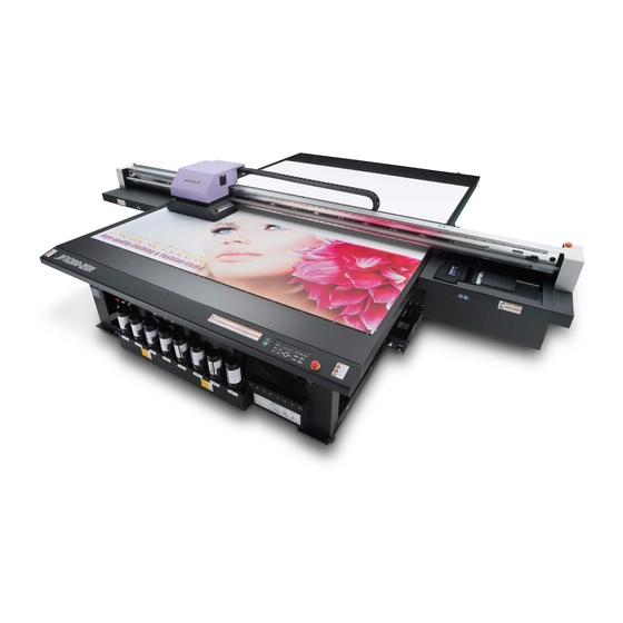
MIMAKI JFX200-2531 Operation Manual
Hide thumbs
Also See for JFX200-2531:
- Requests for care and maintenance (17 pages) ,
- Print manual (28 pages) ,
- Manual (30 pages)

Related Manuals for MIMAKI JFX200-2531


Summary of Contents for MIMAKI JFX200-2531
- Page 1 MIMAKI ENGINEERING CO., LTD. URL: http://mimaki.com/ D203111-10 Original instructions...
-
Page 2: Table Of Contents
TABLE OF CONTENS CAUTION ................v DISCLAIMER OF WARRANTY ........v Requests ................. v FCC Statement (USA) ............. v Interference to televisions and radios ......v Restriction in use .............vi Foreword ................vii About usable ink .............vii On This Operation manual ..........vii Safety Precautions .............viii Symbols ................. - Page 3 Perform head cleaning depending on the test printing result ................2-15 Printing Data ..............2-16 Starting a Printing Operation ..........2-16 Stopping a printing operation halfway ......2-17 Deleting Received Data (Data Clear) ......2-17 Move the Y-bar ...............2-18 Chapter 3 Extended Functions Changing origin ..............3-2 Changing origin with JOG keys ........3-2 Changing origin with FUNCTION menu ......3-3 Registering the thickness of the media ......
- Page 4 Setting Print Mode ............3-44 Initializing the Settings .............3-45 Confirming Machine Information ........3-46 Check the using status of the machine ......3-46 Check the machine version information ......3-47 Displaying the Information of this machine ..... 3-48 Chapter 4 Maintenance Maintenance ..............4-2 Precautions for Maintenance ..........
- Page 5 Chapter 5 Troubleshooting Troubleshooting ..............5-2 Power does not turn on .............5-2 The machine does not start printing .........5-2 Image quality is poor ............5-3 Nozzle is clogged ..............5-3 Ink bottle warning appears ..........5-4 If a Message “SHAKE WHITE INK BOTLES” Appears ..5-5 If an error related to the sub tank occurs (Error 618 to 61b) .............5-6 If negative pressure abnormality occurs ......5-7...
-
Page 6: Caution
Operation of this equipment in a residential area is likely to cause harmful interference in which case the user will be required to correct the interference at his own expense. In the case where MIMAKI-recommended cable is not used for connection of this device, limits provided by FCC rules can be exceeded. -
Page 7: Restriction In Use
CAUTION Restriction in use Restriction in use This machine is very dangerous as it has high-speed movable part, hot part and UV irradiating part. Use of this machine is limited to the user who understands this dangerousness completely. Restriction for user The user of this machine shall get proper training. -
Page 8: Foreword
Foreword Congratulations on your purchase of MIMAKI color ink jet printer "JFX200 Series" . “JFX200 Series” is a UV inkjet printer that can print with UV ink realizing high speed and high image quality. About usable ink Usable ink for this machine is LUS-150, LUS-200, LH100, LUS-120,LUS-350 (4-color/ 4-color+white ink / 4- color+white + clear ink model). -
Page 9: Safety Precautions
Safety Precautions Symbols Symbols are used in this Operation Manual for safe operation and for prevention of damage to the machine. The indicated sign is different depending on the content of caution. Symbols and their meanings are given below. Please follow these instructions as you read this manual. Examples of symbols Meaning Failure to observe the instructions given with this symbol can result in death or serious injuries... -
Page 10: Warning For Use
Warning for Use WARNING • Be sure to setup the appropriate air-moving system in case of using the device in a closed room or a room with bad ventilation. • The ink used for this device falls into the category of UN No.3082 and UN Class 9. Since the ink is flammable, never use fire when using the device. - Page 11 Handling the Anti-freezing liquid • Use the exclusive Anti-freezing liquid by Mimaki ,or the machine may be damaged. • If the Anti-freezing liquid or Cooling tank water gets on the skin or clothes, immediately wash it off with soap.
-
Page 12: Precautions In Use
Handling of media • Use media recommended by MIMAKI to ensure reliable, high-quality printing. • Pay attention to the expansion and contraction of the media. Do not use media immediately after unpacking. The media can be affected by the room temperature and humidity, and thus it may expand and contract. - Page 13 • Never use those UV devices other than those • Do not use the unit in a place where there is a recommended by Mimaki. We would take no possibility of being wet, or electrical leakage may responsibility for any troubles caused through occur.
- Page 14 Safety Precautions Cautions on Installation CAUTION A place exposed to direct A place where temperature or On an inclined surface sunlight humidity varies significantly • Use the machine under the following environmental conditions: • Operating environment: 15 to 30 °C (59 to 86 °F) 35 to 65 % (Rh) A place exposed to direct air Around a place where fire is...
-
Page 15: Warning Labels
Warning labels Warning labels are stuck on the machine. Be sure to fully understand the warning given on the labels. If a warning label is illegible due to stains or has come off, purchase a new one from a distributor or our sales office. - Page 16 Warning labels 1:Reorder .M909381 2:Reorder .M903330 3:Reorder .M906115 6:Reorder .M902663 7:Reorder .M905980 8:Reorder .M913783 8:Reorder .M906311 8:Reorder .M906311 9:Reorder .M907935 10:Reorder .M906031 11:Reorder .M910571 12:Reorder .M903764...
-
Page 17: Ec Declaration Of Conformity
AA: AH, B: 0 to 9, C: any alpha-numeric, D: any alphabet, EEE: 001 to 999 Manufacturer MIMAKI ENGINEERING CO.,LTD. 2182-3, Shigeno-otsu, Tomi, Nagano, 389-0512, JAPAN Authorised Compiler MIMAKI EUROPE B.V. in the Community Stammerdijk 7E 1112 AA Diemen, The Netherlands Managing Director Sakae Sagane... - Page 18 xvii...
-
Page 19: Before Use
Chapter 1 Before Use This chapter describes the items required to understand before use, such as the name of each part of the machine or the installation procedures. About installing this machine ......1-2 Safety sensor ..........1-7 Connecting Cables ........1-8 Where to Install This Machine ..... -
Page 20: About Installing This Machine
Model Width Depth Height Gross weight JFX200-2531 4400mm 4290mm 1250mm 1000kg • A service engineer will perform installation work of this machine. At this time, he/ she will contact you and explain about the usage and the installation of this machine. After fully understanding that content, use this machine safely. -
Page 21: About Fixing Machine
About installing this machine About fixing machine The leg of this machine has the level foot to fix the machine. Before turning the power ON, make sure that the printer body is fixed with the leveling feet. The printer body may start moving during operation if it is not fixed with the leveling feet. -
Page 22: Names Of Parts And Functions
Names of Parts and Functions Front Side of the Machine Power button Turns on/off the power to Carriage the machine. The carriage is provided with the heads for printing. Warning light Indicates the machine status or absorption status. Waste ink tank Waste ink gathers in this tank. -
Page 23: Operation Panel
Names of Parts and Functions Operation Panel Use the operation panel to make settings for printing or operate this machine. The panel is installed at two positions: On the front side and the rear side. Press to perform the absorption Toggles the printing area while operation on the entire table. -
Page 24: Carriage
Carriage The carriage is provided with the heads for printing and LED UV unit. • Do not expose your naked eyes directly to the light irradiated from the LED UV when it lights. • Do not touch the LED UV unit when it is being lit or just after it is set OFF. -
Page 25: Safety Sensor
Names of Parts and Functions Safety sensor This machine is equipped with safety sensors on the front and rear sides of the station and maintenance area. Any contact with the safety sensor will immediately stop the motor and cut off excitation. When detecting any contact with the safety sensor, this machine displays a confirmation screen. -
Page 26: Connecting Cables
Connecting Cables Connecting USB2.0 Interface Cable Connect the PC and this machine with the USB2.0 interface cable. • Your RIP must be compatible with USB 2.0. • Contact a RIP maker near your location or our office when the USB2.0 interface is not attached to the USB cable Notes on USB 2.0 Interface •... - Page 27 Connecting Cables Removing USB memory If a USB memory module is inserted in the personal computer to which a JFX200 machine is connected, click "Stop" in the "Safely Remove Hardware" window by following the instructions given there first and then remove the module.
-
Page 28: Connecting Power Supply Cable
Connecting Cables Connecting Power Supply Cable FRONT-side table Power cable 10m (supplied part) Main unit three- Supplied power cable Switchboard prong inlet Outlet FRONT-side table Power cable 10m (supplied part) Supplied power cable Main unit three- Switchboard prong inlet Outlet 1-10... -
Page 29: Setting Ink Bottles
Setting ink bottles Take out the ink bottle, and slowly shake it twenty times and more. • To prevent ink from leaking when you shake it, wear gloves and cover the ink bottle cap with a paper towel etc. Being in that status, slowly shake it twenty times and more by flowing ink. •... - Page 30 (2) Tighten the specialized cap using the tightening jig. Tightening jig Align the with the tightening jig. • Tighten until the arrows on the tightening jig are aligned. • Do not tighten the dedicated cap too much. Doing so may damage it. (3) Turn the bottle upside-down and check that ink does not leak.
- Page 31 Setting ink bottles Move the lever on the tank completely from the right to the left side. Insert the IC chip. • Insert the IC chip with the left side with metal upward. If you insert the wrong side by accident, it causes faulty or damage of the IC chip.
- Page 32 Replace the ink bottle Perform as follows when [INK END] or [INK NEAR END] is displayed on the display. When [INK END] is displayed Move the lever on the tank completely from the left to the right end. • Do not ever rotate the ink bottle at all after setting it into the tank.
- Page 33 Setting ink bottles Remove the cap from the used ink bottle. • Use the tightening jig to remove the cap if it is difficult to remove. Refer to P.1-11 “Setting ink bottles” to set the new ink bottle. • Do not leave an ink bottle with the specialized cap attached in a location where it is exposed to light for a long period of time.
- Page 34 For Ink bottle lamps The condition of the ink bottles set in the machine is confirmable with lamps located over the ink bottles. Ink bottle lamps Condition of Ink bottle lamp Description No error There is less ink in the ink bottle (Near End). Or, one month has passed from the Blinks in red.
-
Page 35: Caution In Handling Of Ink Bottles
• Do not shake ink bottles violently. This may result in ink leakage from the ink bottles. • Never refill the ink bottles with ink. This may result in troubles. MIMAKI will not bear any responsibility for any damage caused by the use of the ink bottles refilled with ink. -
Page 36: Media
Media Usable media sizes and notes for handling are described. Usable sizes of media Model JFX200-2531 2580mm Maximum width 3100mm Maximum length 2500mm Maximum printing width Thickness Less than 50mm Less than 325kg Weight *1. 1300mm (FRONT/REAR) when the toggle print function is enabled. - Page 37 Chapter 2 Basic Operations This chapter describes procedures and setting methods for ink and media preparation, and printing. Workflow ............2-2 Head Cleaning ..........2-15 Turning the Power ON/OFF ......2-3 About head cleaning ........2-15 Perform head cleaning depending on Turning the Power ON ........ 2-3 the test printing result ........2-15 Turning the Power OFF .......
-
Page 38: Workflow
Workflow Referring to “Turning the Power ON/OFF” Turning the Power ON/OFF P.2-3). Referring to “Setting a Media” ( P.2-5). Setting a Media Move the irradiation position of Referring to “Move the irradiation position of the the UV lamp UV lamp” ( P.2-8). -
Page 39: Turning The Power On/Off
Turning the Power ON/OFF Turning the Power ON Power button Push the power button. • Push the power button located on the left side of the operation panel. • The firmware version is displayed when the power is turned ON. J F X 2 0 0 S t a r t - u p V e r... -
Page 40: Turning The Power Off
Turning the Power ON/OFF Turning the Power OFF When having ended the operation of the machine, turn the power OFF by pressing the power button located on the front side. Check the following items when turning the power OFF. • If the machine is receiving data from the PC or if there is any data that has not been output yet •... -
Page 41: Setting A Media
Setting a Media This machine can be used with a leaf media. For usable medias, refer to P.1-18 “Usable sizes of media”. Setting the Media • If, within the absorption area, there are suction holes not closed by the media, close such suction holes placing thin sheet form material such as paper, film or tape. - Page 42 On the absorption area The absorption area of JFX-2513 is shown in the following figure. Origin • When changing the point of origin, please refer to P.3-2. • The foot switch toggles ON/OFF for each table.
- Page 43 Setting a Media About the media guide hole There are guide holes into which the attached positioning pin is inserted at the position shown below. Use these as a guide to set the media straight. • You can attach the M3 screw in the marketplace instead of the attached positioning pin. In this case, you can attach the screws in two locations at the left and front of the table.
-
Page 44: Move The Irradiation Position Of The Uv Lamp
Move the irradiation position of the UV lamp When printing with this machine, it is necessary to move the LED UV position according to ink to use (color ink/ white ink). This machine provides three printing methods: Single-layer printing: printing color ink layer on media ... - Page 45 Move the irradiation position of the UV lamp 4-colors + clear ink + white ink (M/K/C/Y/CL/CL/W/W) Printing method UV lamp position Single-layer print that prints color ink layer on media. • Move the right and left UV lamp to the position at 0mm. Single-layer print that prints clear ink layer on media.
- Page 46 (2) Adjustment on LH-100 4-colors (M/M/K/K/C/C/Y/Y) Printing method UV lamp position Single-layer printing: printing color ink layer on media. • Move the right and left UV lamp to the position at 65mm. 4-colors + white ink (M/K/C/Y/M/C/W/W) Printing method UV lamp position Single-layer print that prints color ink layer on media.
- Page 47 Move the irradiation position of the UV lamp • The left and right of the UV lamp at 0mm position at Three layers print that overlap the white ink layer on the primer printing primer layer and then overlap the color ink layer Move to 65mm position at the white and color printing •...
- Page 48 Positioning method of UV lamp This part explains the method to move the UV lamp for right and left of the carriage. Loosen the screw of the lamp you move, slide it. Align the top edge of the arrow with the scale. Screw Screw •...
-
Page 49: Test Printing
Test Printing Print a test pattern to check that there are no discharging defects such as nozzle clogging (slight touching of ink or nozzle missing). Relationship between head row and test pattern The relations between head row and test pattern print position are as follow. Head 1 Head 2 Pattern of... -
Page 50: Test Printing
Test Printing Test Printing Print a test pattern to check that there are no discharging defects such as nozzle clogging (slight touching of ink or nozzle missing). In addition, you can select the orientation of the test pattern to print from two types in order to perform test printing repeatedly. -
Page 51: Head Cleaning
Head Cleaning About head cleaning Check the printed test pattern result and perform cleaning depending on the status. Select one from the three types below: : When lines are bent, when any line is missing SOFT NORMAL : When any line is missing, when colors are mixed : When poor image quality cannot be improved even by NORMAL or SOFT cleaning HARD Perform head cleaning depending on the test printing result... -
Page 52: Printing Data
Printing Data Starting a Printing Operation • To perform toggle printing, refer to P.3-20 "Starting toggle printing". Setting a Media ( P.2-5) (1) Open/Close the suction valve adjusting to the media size. (2) Press the key to light the VACUUM lamp and vacuum the media. -
Page 53: Stopping A Printing Operation Halfway
Printing Data Stopping a printing operation halfway Perform the following operation when stopping a printing operation halfway. < L OCA L > Press the key during printing. DA T A REMA I N • The printing operation stops. • Interrupt data sending at the PC side during the data is sent from the •... -
Page 54: Move The Y-Bar
Printing Data Move the Y-bar When you wish to check the printing results etc., you can move the Y-bar. Set the evacuation position (view position) of the Y-bar in advance. Setting the view position F UNC T I ON Press the key in LOCAL. - Page 55 Chapter 3 Extended Functions This chapter describes the operation procedures for using the machine more conveniently and each setting procedure. Changing origin ..........3-2 printing ............3-24 Changing origin with JOG keys ....3-2 Setting Logical Seek ........3-26 Changing origin with FUNCTION menu ..3-3 Setting UV mode .........3-27 Registering the thickness of the media ..
-
Page 56: Changing Origin
Changing origin The default origin position can be changed. There are following 2 changing methods. Changing with the JOG keys Changing with the ÅgORIGINÅh in the FUNCTION menu • When the toggle print function is enabled, refer to "Changing printing origin" in P.3-20 "Starting toggle printing". -
Page 57: Changing Origin With Function Menu
Changing origin Changing origin with FUNCTION menu To precisely set the origin of coordinates, set its X- and Y- coordinates from the FUNCTION menu. This setting value becomes the origin position (0, 0). F UNC T I ON Press the key in LOCAL. -
Page 58: Registering The Thickness Of The Media
Registering the thickness of the media Register the thickness of loading media. There are three types of registering; “Register the thickness of the media manually”, “Adjust the gap with the keys”, and “Measuring the thickness of the media automatically”. • When the toggle print function is enabled, refer to "Changing printing origin" in P.3-20 "Starting toggle printing". Register the thickness of the media manually F UNC T I ON Press the... -
Page 59: Measuring The Thickness Of The Media Automatically
Registering the thickness of the media Measuring the thickness of the media automatically Thickness of media is automatically measured with the gap pin on the left of the carriage. Set a media. • Be sure to set a media on the printing area. If measured automatically without media, the head can break. -
Page 60: Registering Head Gap Value
Registering Head gap value Set the head gap (height from the media to the nozzle plane of the heads). When the carriage is to move above the platen for printing or maintenance, it moves while keeping the head gap at the preset value. The upper limit of the head gap varies with media thickness. -
Page 61: Toggle Printing
Toggle Printing You can divide the printing area into two areas and toggle the area for each printing. While printing in one area, you can set a media for the other area to reduce the time required for media setting. While printing the FRONT-side area, set the While printing the REAR-side area, set the media for the REAR-side area. -
Page 62: Enabling The Toggle Print Function
Enabling the toggle print function To enable the toggle print function, set the toggle print from the FUNCTION menu. When the toggle print function is set to OFF, toggle printing is disabled. When the toggle print function is set to ON, toggle printing is enabled. F UNC T I ON Press the key in LOCAL. -
Page 63: Deciding The Setting Procedure For The Settings Related To Front/Rear Printing Area
Toggle Printing Press the key several times to end the setting. Deciding the setting procedure for the settings related to FRONT/REAR printing area Two types of setting procedures are available. The settings for each area are set individually. INDIVIDUAL When the settings for one area are set, the same values are applied to the other area. COMMON •... -
Page 64: Setting Automatic Area Toggling For Toggle Printing
Setting automatic area toggling for toggle printing Set whether to toggle the printing area automatically after online drawing. For details about setting Work Change while the toggle print function is set to OFF, refer to P.3-33 "Setting Work Change". F UNC T I ON Press the key in LOCAL. - Page 65 Toggle Printing Press to select a set value. WORK CHANGE V ACUUM : OF F • OFF: Turns OFF the vacuum for the area where printing has completed after automatic toggling of print area. • ON: Vacuum for the area where printing has completed stays ON after automatic toggling of print area. Press the key.
-
Page 66: How To Check Printing Area While Toggle Printing Is Enabled
How to check printing area while toggle printing is enabled You can check the printing area from the local screen. You can check the printing area from the local screen. When [R] is displayed, printing is performed for the REAR-side area. Printing area For FRONT side For REAR side... - Page 67 Toggle Printing Press to select [PRINT AREA]. TOGG L E PR I N T PR I N T AREA [ EN T ] Press the key. PR I N T AREA : F RON T PR I N T AREA Press to select an area.
-
Page 68: Registering The Thickness Of The Media
Registering the thickness of the media Register the thickness of the media manually • For the setting procedure when the toggle print function is set to OFF, refer to P.3-4 "Register the thickness of the media manually". • When [[F]/[R] SETUP] is set to "COMMON", the same setting procedure is used as with the case where the toggle print function is set to OFF. - Page 69 Toggle Printing Adjust head gap with the [UP] or [DOWN] keys • For the setting procedure when the toggle print function is set to OFF, refer to P.3-4 "Adjust head gap with the [UP] or [DOWN] keys". Press the key. AREA : F RON T Press...
-
Page 70: Measuring The Thickness Of The Media Automatically
Measuring the thickness of the media automatically • For the setting procedure when the toggle print function is set to OFF, refer to P3-5 "Measuring the thickness of the media automatically". Set a media. • Be sure to set a media on the printing area for the area to measure the thickness. If measured automatically without media, the head can break. -
Page 71: Registering Head Gap Value
Toggle Printing Press the key. T H I CKNE S S CHECK < F > * * CHECK I NG * * • The media thickness will be measured automatically. • The measured thickness will be displayed. T H I CKNE S S CHECK < F > 1 . -
Page 72: Changing Printing Origin
Changing printing origin Changing printing origin with JOG keys • For the setting procedure when the toggle print function is set to OFF, refer to P.3-2 "Changing origin". Press in LOCAL. • The origin mode starts. When is pressed, proceed to step 4. <... - Page 73 Toggle Printing Changing printing origin with FUNCTION menu • For the setting procedure when the toggle print function is set to OFF, refer to P.3-2 "Changing origin". • When [[F]/[R] SETUP] is set to "COMMON", the same setting procedure is used as with the case where the toggle print function is set to OFF.
-
Page 74: Starting Toggle Printing
Press the key several times to end the setting. • The set value is not cleared by cutting the power. Starting toggle printing • Before starting printing, check the settings. Item Check TOGGLE PRINT Whether set to "ON" Whether set to "ON" or "AUTO" SETUP WORK CHANGE Whether VACUUM is set properly... - Page 75 Toggle Printing Start printing. After completion of printing, transmit data to be printed to the other area. Start printing for the other area. Take out the media for the area where printing has completed. • When VACUUM in [WORK CHANGE] is set to OFF, the vacuum for the area where printing has completed is automatically turned to OFF.
-
Page 76: Print Functions With Printing Area Selection
Toggle Printing Print functions with printing area selection When the toggle print function is set to ON, select a print area before starting the following prints: • TEST PRINT (P.2-13) • DROP.POScorrect (P.3-24) • NOZZLE RECOVERY (P.4-20) • LIST (P.3-30) •... -
Page 77: List Of Functions
List of Functions This section describes the overview of each function to be set and set values that can be registered in user types. • About default “HOST” function You can operate this by the setting value specified in RIP software. When you set to other than “HOST”, it operates by that setting value, not by the instruction from RIP software. -
Page 78: Correct The Ink Drop Position For Bidirectional Printing
Correct the ink drop position for bidirectional printing When the condition for printing (media thickness/head height/etc.) has been changed, perform the following operation to correct the ink drop position for bidirectional (Bi) printing and obtain the proper printing result. Example of a Drop Position correct Printed Pattern Output direction The dots at the fourth position counted from the zero... - Page 79 Correct the ink drop position for bidirectional printing Press to correct the dot position of Pattern P A T T ERN 1 0 . 0 • Corrected feeding rate: -40.0 to 40.0 • Check the test patterns. The position where an outward feeding line and a return feeding line become one straight line is the correction value.
-
Page 80: Setting Logical Seek
Setting Logical Seek The motion of Head varies depending on the set of Logical-seek. • You cannot specify the logical seek at the RasterLink side. When you set this machine to “Host”, printing will be performed in “LOGICAL SEEK=ON” status. MACHINE LENGTH MEDIA Movement of heads when... -
Page 81: Setting Uv Mode
Setting UV mode Set the emission pattern and illumination intensity for the UVLED. Press the key in LOCAL. F UNC T I ON V I EW [ EN T ] S E T UP Press to select [SET UP], and the press F E ED COMP . -
Page 82: Perform Setting To Reduce Stripes Between Passes
Perform setting to reduce stripes between passes What is the MAPS Function? If performing media correction does not resolve feeding stripes, use the MAPS (Mimaki Advanced PassSystem) function to disperse the pass boundary to make the feeding stripes less visible. -
Page 83: Setting Maps2 Function (4 Color)
Perform setting to reduce stripes between passes Press the key. S E T UP MA PS [ EN T ] Press the key several times to end the setting. Setting MAPS2 Function (4 color) Press the key in LOCAL. F UNC T I ON S E T UP [ EN T ] S E T UP... -
Page 84: Setting Maps2 Function (4Color + Special Color Ink)
Press to select pattern to print. MA PS 2 P A T T ERN : 2 • AUTO : A pattern that matches the print mode will be set automatically. • Pattern 1 to 5 : The pattern that you select will be printed. •... - Page 85 Perform setting to reduce stripes between passes Press the key. MA PS : OF F Press to select “MAPS2” and press the MA PS 2 : AU TO key. • Set Value:MAPS1, MAPS2, OFF • If you selected OFF, proceed to step 11. MA PS 2 Press to select “AUTO”...
-
Page 86: Perform Setting To Reduce Stripes Between Passes
Perform setting to reduce stripes between passes (6) Press the key. < S POT > • A screen for setting SMOOTHING.LV will appear. SMOOT H I NG L V . : AU TO (7) Press to set the SMOOTHING LV. . <... -
Page 87: Setting Work Change
Setting Work Change • When the toggle print function is enabled, refer to "Setting automatic area toggling for toggle printing" in P.3-20 "Starting toggle printing". Set whether to return to the local mode or keep the remote mode after online drawing. F UNC T I ON Press the key in LOCAL. - Page 88 Setting Work Change Press to select a set value. S E TUP WORK CHANGE [ EN T ] • This setting is enabled only while the toggle print function is enabled. • For the setting procedure, refer to "Setting automatic area toggling for toggle printing" in P.3-7 "Toggle printing".
-
Page 89: Setting Ionizer
Setting Ionizer Set the operation when the ionizer is installed. • If you have installed the ionizer but these settings fail to appear, contact the distributor or a MIMAKI sales office or call center. Press the key in LOCAL. F UNC T I ON... -
Page 90: Setting Auto Cleaning
Setting Auto Cleaning You can set the machine so that it counts the number of printed files or the length after printing has been completed, and performs cleaning automatically if required. The machine can perform a stable printing operation with its heads always kept clean. F UNC T I ON Press the key in LOCAL. -
Page 91: Setting Nozzle Face Cleaning Time
Setting nozzle face cleaning time Cleaning of the head nozzle face is performed automatically before printing begins in order to remove any ink adhering to the nozzle face. Press the key in LOCAL. F UNC T I ON V I EW [ EN T ] F UNC T I ON Press... -
Page 92: Other Settings
Other Settings Change the settings according to the types of use. Press the key in LOCAL. F UNC T I ON V I EW [ EN T ] F UNC T I ON Press to select [SET UP]. S E TUP [ EN T ] Press the key. -
Page 93: Machine Settings
Machine Settings Machine settings are functions for using this machine easily. The following items can be set in Machine settings. Item Set value Default Meaning When no operation has been performed for the NONE/ AUTO Power-off 30min set time, the power supply is automatically P.3-39) 10 ~ 600min turned “OFF”. -
Page 94: Setting Time
Setting Time You can set time of your country (time difference). F UNC T I ON Press the key in LOCAL. V I EW [ EN T ] Press to select [MACHINE SETUP]. F UNC T I ON MACH I NE SE T UP [ EN T ] MACH I NE SE T UP Press the... -
Page 95: Setting Units
Machine Settings Setting Units Units used by this machine are set. F UNC T I ON Press the key in LOCAL. V I EW [ EN T ] Press to select [MACHINE SETUP]. F UNC T I ON MACH I NE SE T UP [ EN T ] MACH I NE SE T UP Press the... -
Page 96: Setting A Key Buzzer
Setting a KEY BUZZER You can turn off the buzzer sound when pressing the key. F UNC T I ON Press the key in LOCAL. V I EW [ EN T ] Press to select [MACHINE SETUP]. F UNC T I ON MACH I NE SE T UP [ EN T ] MACH I NE SE T UP... -
Page 97: Setting A Language
Machine Settings Setting a LANGUAGE You can change the displayed language. Press the key in LOCAL. F UNC T I ON V I EW [ EN T ] F UNC T I ON Press to select [MACHINE SETUP]. MACH I NE SE T UP [ EN T ] Press the key. -
Page 98: Setting Print Mode
Machine Settings Setting Print Mode Use this setting when you want to prioritize the printing speed or when an error occurred on the linear encoder. Press the key in LOCAL. F UNC T I ON V I EW [ EN T ] F UNC T I ON Press to select [MACHINE SETUP]. -
Page 99: Initializing The Settings
Initializing the Settings You can return the setting of “SETUP”, “MAINTENANCE” and “MACHINE SETUP” to the status before shipment. F UNC T I ON Press the key in LOCAL. V I EW [ EN T ] Press to select [MACHINE SETUP]. F UNC T I ON MACH I NE SE T UP [ EN T ]... -
Page 100: Confirming Machine Information
Confirming Machine Information The information of this machine can be confirmed. The following items can be confirmed as machine information. Item Description WIPING PRINT LENGTH PRINT AREA USAGE The information of this machine can be confirmed. USE TIME WASTE INK TANK UV LAMP VERSION This displays the firmware version of the machine. -
Page 101: Check The Machine Version Information
Confirming Machine Information Check the machine version information F UNC T I ON Press the key in LOCAL. V I EW [ EN T ] Press to select [INFORMATION]. F UNC T I ON I N FORMA T I ON [ EN T ] I N FORMA T I ON Press the... -
Page 102: Displaying The Information Of This Machine
Confirming Machine Information Displaying the Information of this machine L US - 1 5 0 MMKKCCK K Press the key in LOCAL. REMA I N 9 9 9 9 9 9 9 9 The information is displayed sequentially with the key . -
Page 103: Maintenance
Chapter 4 Maintenance This chapter describes the items required to use this machine more comfortably, which are the methods for the daily care, the maintenance of the ink unit etc. Maintenance ..........4-2 Setting the Cleaning Intervals ....4-26 Replacing consumables ......4-27 Precautions for Maintenance ...... -
Page 104: Maintenance
Maintenance Maintain the machine regularly or as necessary so that its accuracy will be maintained and it can continue to be used for a long time. Precautions for Maintenance Pay attention to the following items when maintaining this machine. • When using cleaning solution for maintenance, be sure to wear the supplied protective glasses. •... -
Page 105: Mbis Maintenance
Maintenance MBIS Maintenance There is a cotton pad attached to the cap wiper section on the rear of the tank that is used to wipe off any ink adhering to the underside of the cap when replacing ink bottles of the MBIS. Periodically replace the cotton pad. -
Page 106: Maintaining The Capping Station
Maintaining the Capping Station Maintain the ink cap, wiper, etc. located in the capping station. (SATION MAINT.) The ink cap and wiper function as follows. • Wiper : It wipes off ink sticking to the head nozzles. • Ink cap : It prevents the head nozzles from clogging due to dryness. As the machine is used repeatedly, the wiper and ink cap gradually become dirty with ink, dust, etc. - Page 107 Maintaining the Capping Station Remove the wiper. Projection • Pull out the wiper by holding the protrusions at its both ends. Clean the wiper and bracket. Wiper • Wipe off the ink sticking to the wiper and bracket with a clean stick dipped in cleaning liquid for maintenance.
- Page 108 Clean the cap rubber and cap rubber cover. • Wipe off the ink sticking to the cap rubber and cap rubber Cap rubber cover with a clean stick dipped in cleaning liquid for maintenance. Cap rubber cover Wipe off so that cleaning solution for maintenance will not remain.
-
Page 109: Cleaning The Around Station
Maintaining the Capping Station Cleaning the around station It is recommended that the wiper and cap be cleaned frequently in order to maintain the high image quality of the machine and keep the machine itself in good working order. • Clean the station and the area around it about twice a week (it varies, depending on frequency in the use of the machine). -
Page 110: Cleaning The Head And The Area Around It
Cleaning the Head and the Area around It Because the head employs a very precise mechanism, due care needs to be taken when it is cleaned. Using a clean stick, etc., rub off gelatinous ink or dust that may stick to the lower part of the slider and the area around the head.In doing so, never rub the nozzles of the head. - Page 111 Cleaning the Head and the Area around It Wipe ink sticking to the side of the head off with a clean stick. • Never rub the nozzles. The nozzle part (Never Clean the side surface of the head (shown in deep gray) with a clean stick. touch it.) Clean with a clean stick.
-
Page 112: Washing The Ink Discharge Passage (Disway Wash)
Washing the Ink Discharge Passage (DISWAY WASH) Wash the ink discharge passage regularly to prevent the head nozzles from clogging due to ink coagulation inside the passage. CARR I AGE OU T Press the key in LOCAL. [ EN T ] Press to select [DISWAY WASH]. -
Page 113: When The Machine Is Not Used For A Long Time (Custody Wash)
Cleaning the Head and the Area around It When the Machine Is Not Used for a Long Time (CUSTODY WASH) When the machine is not going to be used for a week or more, use the cleaning function for custody to clean the head nozzles and ink discharge passage.After this, keep the machine in custody. - Page 114 Press the key. CA P C L E AN I NG COMP L E T ED ( NEX T ) [ EN T ] • The carriage moves onto the platen. • Until wiper cleaning is competed, [COMPLETED (NEXT): ENT] is displayed on the screen. After the work up to the step 6 is completed, press the key.
- Page 115 Cleaning the Head and the Area around It Fill up the cap with cleaning solution for maintenance, using a dropper. • Fill the cap with the cleaning solution just before the solution overflows from the cap. Press the key. CUS TODY WA SH P L E A SE WA I T •...
-
Page 116: When Nozzle Clogging Cannot Be Solved
When Nozzle Clogging Cannot Be Solved When nozzle clogging cannot be solved even after the head cleaning ( P.2-15) has been done, perform the following two functions: • Fill the head with ink. ( P.4-14) HEAD FILLUP • Wash the head nozzle. ( P.4-15) NOZZLE WASH •... -
Page 117: Washing Of Head Nozzle
When Nozzle Clogging Cannot Be Solved Washing of Head nozzle Perform cleaning of the nozzles in the heads to prevent them being clogged with coagulated ink. Is [INK END] displayed? • The ink is absorbed when the nozzles are washed. Check the items on the At this time, if the state of "INK END"... - Page 118 Cap rubber Clean the cap rubber and cap rubber cover. • Wipe off the ink sticking to the cap rubber and cap rubber cover with a clean stick dipped in cleaning solution for Cap rubber maintenance. Wipe off so that cleaning solution for cover maintenance will not remain.
-
Page 119: If Nozzle Missing Due To Color Mixture Of Ink Or Aeration
When Nozzle Clogging Cannot Be Solved If nozzle missing due to color mixture of ink or aeration If nozzle missing occurs due to color mixture of ink in the head or aeration, push ink or air in the head out from the port. - Page 120 Open, one at a time, the ink port caps on the side you selected in step 3. • Be sure to carry out air purging on only one port at a time. • Do not open the port cap at the side you did not select in the Step 3.
- Page 121 When Nozzle Clogging Cannot Be Solved Perform the procedures from 9 to 10 on all ports which have to be purged the air. • Attach the jig to the port from which you want to purge air and press the key to release air from the machine.
-
Page 122: Alternative Nozzles For Printing, When Nozzles Missing Can Not Be Improved
Alternative nozzles for printing, when nozzles missing can not be improved NOZZLE RECOVERY: When nozzles missing can not be improved at specific points, other good nozzles can be used as alternatives for printing. The head of this machine consists as the right figure. You can set the recovery by specifying the nozzle line each for the H1-2 (Head 1-2). - Page 123 When Nozzle Clogging Cannot Be Solved Press to select the Nozzle line that needs SE L EC T NOZ Z L E NOZZLE RECOVERY and press the key. : H 1 - A Nozzle line: A,B,C,D Head No.: H1 or Register the Nozzle number that needs NOZZLE H 1 - A RECOVERY and press the...
- Page 124 Check if the registered nozzle is recovered You can check whether registered nozzle has been successfully recovered. With the following settings “ON”, you can print a test pattern using a recovered nozzle when test print ( P.2- 13). Select [NOZZLE RECOVERY] of the maintenance menu.
- Page 125 When Nozzle Clogging Cannot Be Solved At the time of the start of printing, check whether or not there is a nozzle that can not be recovered Depending on the print conditions that have been set, there are times when it can not be recovered even register the nozzle recovery.
- Page 126 When Nozzle Clogging Cannot Be Solved Clear the set value Select [NOZZLE RECOVERY] of the maintenance menu. (1) Press the key in LOCAL. (2) Press to select [MAINTENANCE] and press the key. (3) Press to select [NOZZLE RECOVERY]. (4) Press the key.
-
Page 127: Automatic Maintenance Function
Automatic Maintenance Function To use this machine comfortably, you can set various maintenances to be performed automatically. Here, set performing intervals of various automatic maintenances. You can prevent troubles such as ink clogging by performing automatic maintenance periodically (automatic maintenance function). For the auto maintenance functions, the following items can be set: •... -
Page 128: Setting The Cleaning Intervals
Automatic Maintenance Function Setting the Cleaning Intervals The cleaning type and the interval between each cleaning operation are set. Select [AUTO MAINT.] of the maintenance menu. (1) Press the key in LOCAL. (2) Press to select [MAINTENANCE] and press the key. -
Page 129: Replacing Consumables
Replacing consumables Replacing the wiper The wiper is consumable.When the display indicates that it is necessary to < L OCA L > replace the wiper, immediately replace the wiper with a new one. R e p l a c e a WI P ER [ M N T ] Also, wipe ink sticking to the lower surface of the slider off. -
Page 130: If A Waste Ink Tank Confirmation Message Appears
If a Waste Ink Tank Confirmation Message Appears Ink used in head cleaning, etc. is stored in the waste ink tank on the lower right side of the machine. This machine counts the accumulated amount of discharged ink. When that reaches a specified amount, the machine displays a confirmation message.(When this message is displayed, consider the replacement of the waste ink tank.) •... -
Page 131: Disposing Of Waste Ink
Replacing consumables Disposing of waste ink • Be sure to wear the supplied goggles and gloves when disposing the waste ink tank. Otherwise, you may get ink in your eyes. • Do not replace the waste ink tank while this machine operates (during printing or cleaning). •... - Page 132 Move waste ink to a polyethylene tank and return the empty waste ink tank to the original position. (1) As indicated in the right figure, move waste ink pooled in the waste ink tank to another polyethylene tank. (2) Hold the handle of the waste ink tank and insert it along the rail.
-
Page 133: Replacing The Waste Ink Tank Before The Waste Ink Tank Confirmation Message Is Displayed
Replacing consumables Replacing the waste ink tank before the waste ink tank confirmation message is displayed if you replace the waste ink tank before the waste ink tank confirmation message is displayed (before the 2L tank is 80% (1.6L) full), set the waste ink information to 0% in the Information menu. Perform steps 3 through 6 in “Disposing of waste ink”... -
Page 134: Replacing The Waste Ink Tank Before The Waste Ink Tank Confirmation Message Is Displayed
Replacing consumables Replacing the waste ink tank before the waste ink tank confirmation message is displayed Set the waste ink information to 0% in the maintenance menu. Perform steps 3 through 6 in "Disposing of waste ink" ( P.4-29) to empty the waste ink tank. -
Page 135: Refilling Antifreeze Mixed Water
Precautions in handling the antifreeze liquid • Be sure to wear goggle and gloves for handling the antifreeze liquid. • Use the recommended antifreeze liquid by Mimaki. If not, the cooling device may be broken. (Supplied antifreeze liquid :1000cc x 2 bottles) •... -
Page 136: Refill Cooling Water
Refill cooling water If an error of lack of water, refill cooling water. To fill up its capacity, about 500cc refill is required. • If leave the error message of lack of water without refilling cooling < L OCA L > water after one week, the error display on the display switches to RE F I L L WA T ER "REFIL WATER". - Page 137 Refilling antifreeze mixed water Refill antifreeze liquid. • Fill the antifreeze liquid from the feed-water inlet. • Fill the syringe with mixed water and inject while checking the level indicator. Stop injecting when the red part is visible. • Be sure to check the level indicator as you inject the mixed water.
-
Page 138: Exchange The Flushing Filter
Exchange the flushing filter • Cleaning liquid for maintenance (SPC-0568) Tools required for Exchabge • Waste cloth • Gloves • Goggles • Be sure to wear the supplied goggles and gloves when exchanging theflushing filter. Since the ink is absorbed in the Flushing filter, you may get ink in your eyes. If a Flushing Filter Exchange Message Appears The flushing filter needs to be replaced periodically. -
Page 139: Replacing The Flushing Filter Before The Replacement Message Is Displayed
Exchange the flushing filter Replacing the flushing filter before the replacement message is displayed Select [STATION] of the maintenance menu. (1) Press the key in LOCAL. (2) Press to select [MAINTENANCE] and press the key. (3) Press to select [STATION]. (4) Press the key. -
Page 140: Ionizer Maintenance
Ionizer maintenance • Before taking care of it, be sure to turn off the main power switch of the main body. You may get an electric shock. Also, you may get injured collaterally. • Do not touch the electrode probe directly. You may get injured. Be careful to work. •... - Page 141 Wipe off the electrode probe and around it with a cotton swab immersed in alcohol. • Recommended: ethyl alcohol, isopropyl alcohol When it is very dirty • Use an ultrasonic bath. Also, you can use alcohol as washing liquid. • After cleaning, fully dry it and then attach it to the ionizer to use. If cleaning liquid remains on the electrode probe, it may cause an accident or failure of the machine.
-
Page 142: Clean With Electrode Probe Cleaning Kit (Spa-0237)
Clean with Electrode Probe Cleaning Kit (SPA-0237) Explain the filter exchange method of Electrode Probe Cleaning Kit (SPA-0237). • Do not touch the electrode probe directly. You may get injured. Be careful to work. • Do not touch the electrode probe with a hard thing such as a tool. It may cause an accident or failure of the machine. - Page 143 Ionizer maintenance Installing the Filter Explain the filter exchange method of Electrode Probe Cleaning Kit (SPA-0237). Cleaning Kit Replacement Filter • After the filter is used to clean multiple electrode probes, dust becomes attached to the filter and the cleaning abilities are reduced. •...
-
Page 144: Clean The Electrode Inner Wall
Clean the electrode inner wall Electrode Probe Cleaning Kit 2 (SPA-0239) is used to clean the inner wall of the electrode probe cap. When clean the tip of the electrode Probe, please use Electrode Cleaning Kit (SPA-0237). • Electrode Probe Cleaning Kit 2 (SPA-0239) Tools required for maintenance •... - Page 145 Ionizer maintenance Installing the Filter Explain how to replace the filter of Electrode Probe Cleaning Kit 2(SPA-0239). Cleaning Kit 2 Replacement Filter • After the filter is used to clean multiple electrode probes, dust becomes attached to the filter and the cleaning abilities are reduced.
-
Page 146: Alarm Output Function
Ionizer maintenance Alarm output function This ionizer has the function to output alarms. Alarm output part Indicator light Alarm function Item Alarm (ALM) Ion level (ION) Condition (COND) Indicator light blinks three times Indicator light blinks twice about Indicator light blinks. - Page 147 Chapter 5 Troubleshooting This chapter describes the corrective measures to be taken for a phenomenon suspected to be trou- ble and the procedures to clear the error number displayed on the LCD. Troubleshooting ................5-2 Power does not turn on ..............5-2 The machine does not start printing ..........5-2 Image quality is poor ...............5-3 Nozzle is clogged ................5-3...
-
Page 148: Troubleshooting
Troubleshooting Take appropriate actions as described below before taking the trouble as a failure. If still the problem is not solved after troubleshooting, contact your dealer or an office of MIMAKI. Power does not turn on In most cases, this is due to improper connection of the power cable for the machine or computer. Check that the power cable is connected properly. -
Page 149: Image Quality Is Poor
This section describes the corrective actions to be taken in case the image quality is not satisfactory. Take remedy for particular problems with image quality. If the remedy does not work, contact your dealer or an office of MIMAKI. Phenomenon Measures (1) Execute the head cleaning. -
Page 150: Ink Bottle Warning Appears
• Once ink bottle trouble is displayed, do not leave the ink bottle without replacing it for a long time; otherwise, the machine will lose the nozzle clogging prevention function. If nozzles are clogged, the machine must be repaired by MIMAKI's service engineer. Displaying the description of ink bottle trouble The contents of ink bottle error are confirmable by the following operations. -
Page 151: If A Message "Shake White Ink Botles" Appears
Troubleshooting If a Message “SHAKE WHITE INK BOTLES” Appears White ink tends to settle, so you must periodically shake the ink bottles. SHAK E WH I T E I NK If using white ink, a message will be displayed periodically instructing you to BOT L E S [ EN T ] shake the white ink bottle. -
Page 152: If An Error Related To The Sub Tank Occurs (Error 618 To 61B)
If an error related to the sub tank occurs (Error 618 to 61b) The Error 618 to 61b are related to the sub tank. Execute following procedures when an error about sub tank occurs, or when the nozzle is not unclogged after cleaning. -
Page 153: If Negative Pressure Abnormality Occurs
Troubleshooting If negative pressure abnormality occurs By the environment or aging, the pressure controlled in this machine may exceed the control range. If an error related to pressure abnormality occurs, perform the procedures below: • If pressure abnormality occurs, immediately adjust the pressure with the following procedures and return it to the normal value. -
Page 154: If Pl Enc Sns(L)/(R) Occurs
Troubleshooting Press the key. P L E A SE WA I T • The error is released and the negative pressure control starts. • When an error occurs even after you adjusted the pressure, contact your local distributor to call for service. -
Page 155: Warning / Error Messages
Warning / Error Messages If some trouble occurs, the buzzer sounds and the display shows a corresponding error message. Take an appropriate remedy for the displayed error. Warning messages Errors when performing operations Message Cause Solution • Check the ink bottle for the supply path C A N ‘... - Page 156 Message Cause Solution The value of the negative pressure • Perform “PRESSURE ADJUST” ( P.5- < L OC A L > sensor is abnormal. N E G A T I V E P R E S S U R E 7) of the maintenance.
- Page 157 Warning / Error Messages Ink Error Ink error is displayed also in the local guidance. ( P.3-48) Message Cause Solution • Remove the ink bottle generating the I N K : - - - - Y Y K K warning once and install it again. The IC chip of the ink bottle cannot be •...
-
Page 158: Error Messages
Error messages When an error message is displayed, eliminate the error according to the chart below. If the same error message appears again, contact your dealer or an office of MIMAKI to call for service. Message Cause Solution There is an abnormality in the parame-... - Page 159 Warning / Error Messages Message Cause Solution An error occurred in the main PCB 35- E R ROR 1 5 8 2V power supply. M a i n P C B V 3 5 2 COM driver becomes the high tem- E R ROR 1 5 f perature.
- Page 160 Message Cause Solution E R ROR 3 0 4 USB device initialization failure. U S B I N I T E R R Occurrence of a time out error on a E R ROR 3 0 5 USB device. U S B T I ME OU T E R ROR 4 0 1 An excessive load was applied to the X •...
- Page 161 Warning / Error Messages Message Cause Solution • Perform “SUB TANK” ( P.5-6) of the Though a certain amount was con- maintenance. Even if you performed this, E R ROR 6 1 8 sumed, there is no change in the sub when the message is displayed, contact T A N K l e v e l H : 1 2 3 4 5 6 7 8...
- Page 162 Warning / Error Messages Message Cause Solution • Turn OFF the power of the machine and turn E R ROR 7 1 6 it ON again after a while. I n k H e a t e r L T m p : 1 2 When the power is ON, the screen for selecting whether to control the ink heater is Anomaly temperature of ink heater.
- Page 163 Chapter 6 Appendix This chapter contains the lists of the specifications and functions of this machine. Specifications ..................6-2 Machine specifications ..............6-2 Ink specifications ................6-3 Setting orders depending on ink type ..........6-4 Setting orders of ink bottles .............6-4 Sheet for inquiry ................6-6 Function Flowchart ................6-10...
-
Page 164: Specifications
Specifications Machine specifications Method Drop-on-demand piezoelectric print heads Print head Specification 2 heads: 2-layered staggered arrangement in 1-line 300x450HQ : Bi/Uni 6/12 pass 600x600 : Bi/Uni 8/16 pass 4-colors 600x900 : Bi/Uni 12/24 pass 1200x1200 : Bi/Uni 16/32 pass Printing mode (scan x feed) 300x450HQ : Bi/Uni 12/24 pass... -
Page 165: Ink Specifications
Transportation at temperature of 40˚C is permitted within a month.) Do not use any ink other than MIMAKI designated ink. Also, do not disassemble the ink bottles or refill or replenish their ink. Ink could freeze if kept in a cold place for an extended period. -
Page 166: Setting Orders Depending On Ink Type
Setting orders depending on ink type The setting value and the setting orders of the ink bottles differ depending on the ink type you use. Setting orders of ink bottles The order of the ink bottles that are set differs depending on the ink set that is used. 4-colors ink set 4-colors + white ink set 4-colors + clear + white ink set... - Page 167 Setting orders depending on ink type 4-colors + clear + primer + white ink set 6-colors + white ink set...
-
Page 168: Sheet For Inquiry
Sheet for inquiry Use this sheet for troubles and abnormal functions of the machine. Fill in the following necessary items, and then fax the sheet to our sales office. Company name Person in charge Telephone number machine model Operating OS Machine information Error message Contents of inquiry... - Page 169 Sheet for inquiry...
-
Page 170: Function Flowchart
Function Flowchart < L OC A L > WH I D T H : * * * * mm OR I G I N S E T U P OR I G I N S E T U P 0 . 0 - - - - * * OR I G I N * * OR I G I N S E T U P... - Page 171 Function Flowchart OR I G I N S E T U P OR I G I N S E T U P H E A D GA P = * . * mm ME D I A = * . * mm * * P R I N T I NG * * P L E A S E WA I T * * C L E A N I NG * *...
- Page 172 From P.6-10 DROP . POS c o r r e c t DROP . POS c o r r e c t [ E N T ] P R I N T [ E N T ] L H - 1 0 0 MMCC Y Y K K I N K I C C A N ‘...
- Page 173 Function Flowchart * * P R I N T I NG * * P A T T E RN 1 P A T T E RN 2 P L E A S E WA I T 0 . 0 0 . 0 -40 to 40 -40 to 40 WA RN I NG...
- Page 174 From P.6-12 F UNC T I ON V I EW * * MOV I NG NOW* * V I EW [ E N T ] S T A R T [ E N T ] P L E A S E WA I T V I EW S E T V I EW POS S E T V I EW POS...
- Page 175 Function Flowchart ME D I A T H I C K N E S S P L E A S E WA I T T H I C K N E S S CH E C K T H I C K N E S S CH E C K T H I C K N E S S CH E C K CH E C K S T A R T [ E N T ]...
- Page 176 From P.6-14 From P.6-14 MANUAL S E T U P U V MOD E U V MOD E [ E N T ] : HOS T HOST HOST/PATTERN1, 2 S E T U P R E F R E S H R E F R E S H [ E N T ] : HOS T...
- Page 177 Function Flowchart U V MOD E U V MOD E U V MOD E L I GH T A D J U S T : C o l o r : B i Bi / Uni -50 to +50% Color/ White/ Clear ink U V MOD E U V MOD E : P A T T E RN 1...
- Page 178 From P.6-16 F UNC T I ON MA I N T E N A NC E S T A T I ON MA I N T E N A NC E [ E N T ] S T A T I ON [ E N T ] C A RR I AGE OU T [ E N T ]...
- Page 179 Function Flowchart MOV E POS I T I ON C A RR I AGE OU T : S T A T I ON MA I N T . COMP L E T E D [ E N T ] STATION MAINT. / HEAD MAINT. W I P E R C L E A N I NG C A P C L E A N I NG F i l l...
- Page 180 From P.6-18 From P.6-18 From P.6-18 NO Z Z L E R E COV E R Y : CON F I RM ME NU NO Z Z L E R E COV E R Y : CH E C K B E F OR E P R I N T MA I N T E N A NC E A U T O MA I N T .
- Page 181 Function Flowchart CON F I RM ME NU : O F F ON/ OFF CH E C K B E F OR E P R I N T : O F F OFF/ CONTINUE/ STOP R E F R E S H : L v .
- Page 182 From P.6-20 F UNC T I ON MA CH I N E S E T U P A U T O P o w e r - o f f MA CH I N E S E T U P [ E N T ] A U T O P o w e r - o f f [ E N T ]...
- Page 183 Function Flowchart L E NG T H : mm mm / inch P L E A S E WA I T P R I N T MOD E S E A RCH I NG OR I G I N CH A NGE . OK ? [ E N T ] R E S E T Settings are initialized...
- Page 185 JFX200-2531 Operation Manual Oct. 2016 MIMAKI ENGINEERING CO.,LTD. 2182-3 Shigeno-otsu, Tomi-shi, Nagano 389-0512 JAPAN D203111-10-17102016...
- Page 186 © MIMAKI ENGINEERING CO., LTD.2016...
Need help?
Do you have a question about the JFX200-2531 and is the answer not in the manual?
Questions and answers