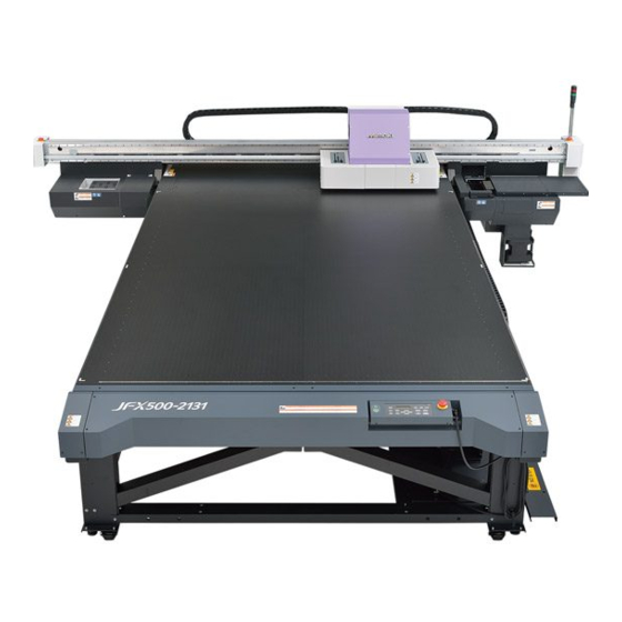
MIMAKI JFX500-2131 Installation Manual
For service engineers; vacuum unit
Hide thumbs
Also See for JFX500-2131:
- Operation manual (156 pages) ,
- Product manual (48 pages) ,
- Safety precautions (36 pages)
Advertisement
Quick Links
For Service Engineers
Vacuum Unit
(OPT-J0330)
Installatioin Guide
Revision 1.1
Contents
Safety Precautions................................................................. 3
Parts list ................................................................................. 4
Work procedures ................................................................... 5
Changing vacuum control unit parameter.............................. 9
MIMAKI ENGINEERING CO., LTD.
URL:http://eng.mimaki.co.jp/
D901827-11
Advertisement

Subscribe to Our Youtube Channel
Related Manuals for MIMAKI JFX500-2131


Summary of Contents for MIMAKI JFX500-2131
- Page 1 For Service Engineers Vacuum Unit (OPT-J0330) Installatioin Guide Revision 1.1 Contents Safety Precautions..............3 Parts list ................. 4 Work procedures ..............5 Changing vacuum control unit parameter......9 MIMAKI ENGINEERING CO., LTD. URL:http://eng.mimaki.co.jp/ D901827-11...
- Page 2 This manual for service engineers provides the necessary setup information for adding a vacuum cable to the flatbed UV inkjet printer JFX500-2131. When performing maintenance work, refer to this manual and the following related documents for details on working procedures.
-
Page 3: Safety Precautions
Safety Precautions Warning signs The meanings of the warning signs used in this manual are described below. Make sure you fully understand the meaning of these warnings before beginning work. Sign Title Meaning Indicates that there is a risk of death or serious injury if the Danger sign directions are ignored or the device is not handled correctly. -
Page 4: Parts List
Parts list Check Check Check Part Cable Part Part Cable clamp Banding band Name (with hexagonal locking screw) Name Name Quantity Quantity Quantity Remark Remark Remark Check Check Check Part Part Part Tiflex hose Hose clamp Cuff Name Name Name Quantity Quantity Quantity... -
Page 5: Work Procedures
Work procedures Turn off the power supply. (1) Move the Y bar to the waiting position (rear of main body). (2) Turn off the sub power switch of the oper- ation panel. (3) Turn off the main power switch on the side of the main body. - Page 6 (2) Fix attached cable on the vacuum unit fix- ing plate with the hexagonal locking screw. (3) Push the cable edge of the opposite side into the hole. Push it into this hole. (4) Fix the vacuum unit fixing plate on the original position with the screw.
- Page 7 Work procedures (2) Pass it through the rear hole of the bear- ing BOX and the side hole of the power supply rear cover (middle one of the three holes). (3) Fix it with the existing clamp inside the power supply BOX. (4) Connect it with CN14 and CN15 of the big/ small feeding and taking-up PCB.
- Page 8 (3) Fix the original hose with the banding band as required. Put the hose newly attached out of the machine from beneath the bottom plate so that it may not contact with the X bearing. Put the hose newly attached here out of the machine from beneath the bottom plate.
-
Page 9: Changing Vacuum Control Unit Parameter
Changing vacuum control unit parameter It is necessary to change the parameter of the vacuum control unit. Operation procedures [PROG/ RESET] key Operation mode [FUNC/ DATA] key Operation mode Program mode Display example 1 “1.F--” “1.E--” “1.C--” --- Menu (Display is changed with []/[]) Display example 2 “F00”... - Page 10 Change the setting of the function code data. • Change three function codes below according to the table below: Function code Name Setting before shipment Changed example Multistage frequency 1 15.00 20.00 Multistage frequency 2 10.00 40.00 Multistage frequency 3 6.00 60.00 •...
- Page 11 Changing vacuum control unit parameter • Function code parameter Function code data Function code Name Default Change value Frequency setting1 Operation Highest output frequency 60.0 60.0 Base frequency 60.0 60.0 Base frequency voltage Acceleration time1 6.00 15.00 Deceleration time1 6.00 15.00 Heat damping time constant Momentary-power-failure reboot...
Need help?
Do you have a question about the JFX500-2131 and is the answer not in the manual?
Questions and answers