Tektronix Phaser 360 Service Manual
Color printer
Hide thumbs
Also See for Phaser 360:
- User manual (252 pages) ,
- Supplementary manual (5 pages) ,
- Network manual (186 pages)
Table of Contents
Advertisement
Quick Links
Service Manual
®
Phaser
360
Color Printer
Warning
The following servicing instructions are for
use by qualified service personnel only. To
avoid personal injury, do not perform any
servicing other than that contained in
operating instructions unless you are qualified
to do so.
This printing: 10-27 1997
070-9923-00
Advertisement
Table of Contents

Related Manuals for Tektronix Phaser 360


Summary of Contents for Tektronix Phaser 360
- Page 1 Service Manual ® Phaser Color Printer Warning The following servicing instructions are for use by qualified service personnel only. To avoid personal injury, do not perform any servicing other than that contained in operating instructions unless you are qualified to do so. This printing: 10-27 1997 070-9923-00...
- Page 2 OS/2® is a registered trademark of International Business Machine Corporation. PANTONE Colors generated by the Phaser 360 Color Printer are four- and/or three-color process simulations and may not match PANTONE-identified solid color standards. Use current PANTONE Color Reference Manuals for accurate color.
-
Page 3: Users Safety Summary
Users safety summary Terms in manual: CAUTION Conditions that can result in damage to the product. WARNING Conditions that can result in personal injury or loss of life. Power source: Do not apply more than 250 volts RMS between the supply conductors or between either supply conductor and ground. - Page 4 Service safety summary For qualified service personnel only: Refer also to the preceding Users Safety Summary. Do not service alone: Do not perform internal service or adjustment of this product unless another person capable of rendering first aid or resuscitation is present. Use care when servicing with power on: Dangerous voltages may exist at several points in this product.
-
Page 5: Table Of Contents
Connecting the printer to a workstation 2-11 Direct connection to a workstation 2-11 Networked connection to a workstation 2-11 Installing a SCSI hard disk drive on a Phaser 360 2-12 Turning on the printer 2-13 Startup page 2-13 Configuration page 2-14... - Page 6 Setting up the Phaser 360 printer driver 2-24 Setting up the Apple LaserWriter 8 printer driver 2-24 Setting up the Phaser 360 GX printer driver 2-25 Installing a printer driver for Microsoft Windows 95 2-26 Installing printer software for Windows NT 4.0 2-28 Installing printer software for Windows NT 3.51 2-30...
- Page 7 Supplies ordering 4-6 If you need help 4-7 Receiving email update notices 4-8 Customer Support Hotline 4-8 Downloading files from the Tektronix Color Printer Information Server 4-9 Using the automated fax systems 4-9 Service support 4-11 Accessing the printer’s web page 4-11...
- Page 8 Oil streaks on top of print 6-16 Error codes and messages 6-17 PC-based diagnostics 6-29 Requirements 6-29 Starting the diagnostics 6-30 Selecting tests 6-33 Running tests 6-35 Saving and restoring test selections 6-40 Saving and restoring other settings 6-40 viii Phaser 360 Color Printer...
- Page 9 The diagnostic pull-down menus summary 6-41 Test Command (Alt-T) 6-41 View Menu 6-41 Run Command 6-41 Next Command 6-41 Stop Command 6-41 File Menu (Alt-F) 6-42 Options Menu 6-42 Help Menu 6-42 Problems and solutions 6-43 Power problems 6-43 Front panel indications 6-43 Macintosh printing problems 6-43 PC DOS printing problems 6-45 Windows printing problems 6-46...
- Page 10 I/O board 1 8-50 I/O board right and transfix solenoid/sensor bracket 8-51 I/O board 4 8-52 Power control board 8-53 Interconnect board 8-55 Main board 8-57 RAM SIMM 8-58 Code ROM SIMM 8-60 Font SIMM 8-61 Network card 8-62 Phaser 360 Color Printer...
- Page 11 Checks and Adjustments Required tools summary 9-1 Front panel menu 9-2 Bypass mode 9-4 Cool down mode 9-4 Printing test prints 9-5 Printing service test prints 9-5 Printing the configuration page 9-5 Adjustments 9-6 Paper-feed belt tension adjustment 9-6 Y-axis belts tension adjustment 9-7 Printhead-to-drum spacing adjustment 9-9 Cap/wipe/purge assembly belt adjustments 9-11 Drum position encoder gap 9-13...
- Page 12 Figures Figure 1-1 The Phaser 360 printer (shown with optional Lower Paper Tray Assembly) 1-1 Figure 1-2 Internal features of the print engine 1-4 Figure 1-3 Circuit boards of the print engine (right front view) 1-5 Figure 1-4 Circuit boards of the print engine (left-rear view) 1-6 Figure 1-5 The printer’s I...
- Page 13 Figure 5-17 Image transfixing, stripping and paper exiting 5-27 Figure 5-18 The printhead maintenance cycle 5-30 Figure 6-1 Measuring the DC voltages (test points) and fuses 6-8 Figure 6-2 Turning off AppleTalk 6-30 Figure 6-3 Configuring SoftPC’s Serial Port 6-31 Figure 6-4 PC-based diagnostics screen display 6-32 Figure 6-5...
- Page 14 Connecting the vacuum gauge to the printer 9-15 Figure 9-10 Selecting the vacuum check test 9-16 Figure 9-11 NVRAM menu 9-17 Figure 9-12 Viewing NVRAM contents 9-18 Figure A-1 The printer exterior FRUs A-3 Figure A-2 The printer interior FRUs A-7 Phaser 360 Color Printer...
- Page 15 Figure A-3 The printer interior FRUs (left side) A-9 Figure A-4 Lower Paper Tray Assembly FRUs A-10 Figure C-1 Print engine wiring diagram C-1 Figure C-2 Wire routing on the right side of the printer near I/O board right C-2 Figure C-3 Wire dressing above the x-axis drive C-2 Figure C-4...
- Page 16 Table A-1 FRU exterior parts list A-2 Table A-2 FRU interior parts list A-4 Table A-3 FRU interior part list (left side) A-8 Table A-4 supplies and accessories A-9 Table A-5 Lower Paper Tray Assembly FRUs A-10 Phaser 360 Color Printer...
-
Page 17: General Information
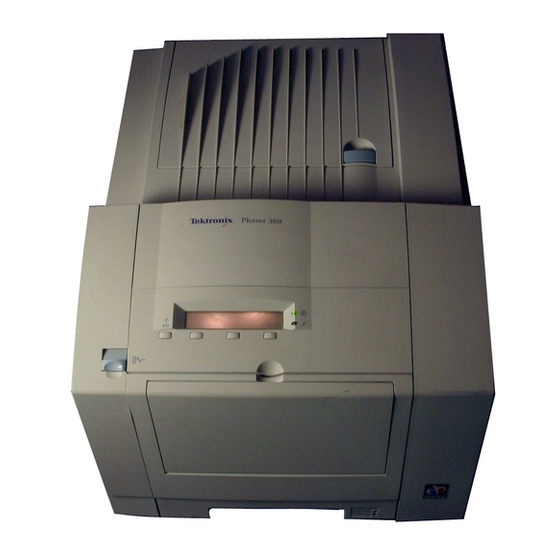
FRU list. To ensure complete understanding of the product, we recommend participation in Phaser 360 service training, if available. 9923-01 Figure 1-1 The Phaser 360 printer (shown with optional Lower Paper Tray Assembly) Service Manual... -
Page 18: Phaser 360 Overview
The Phaser 360 features 164 built-in fonts, and is equipped with 24 Mbytes of RAM. It can be upgraded to 48 MB of RAM. The Phaser 360 is capable of job pipelining; it can print one image and process the data for the next image at the same time. -
Page 19: Solid Inks
Memory considerations With its total of 24 Mbytes, the Phaser 360 prints in Fast Color, 300 x 300 dpi and 450 x 800 dpi modes, job pipeline images, quickly off-load images from the host, and store downloadable fonts. Upgrading the printer to 48 Mbytes of RAM provides maximum performance through greater image throughput, more virtual memory and greater data port buffering. -
Page 20: Print Engine Assemblies
Print engine assemblies Ink load assembly Cap/wipe/purge assembly Drum Power supply Transfix roller Printhead Process motor X-axis Maintenance tray drive X-axis motor Y-axis motor Paper pre-heater Drum heater 9923-02 Figure 1-2 Internal features of the print engine Phaser 360 Color Printer... -
Page 21: Figure 1-3 Circuit Boards Of The Print Engine (Right Front View)
General Information Ten circuit boards support the printer’s electronics. Three boards, called I/O boards support the front panel, solenoids and sensors. I/O board 4 is contained inside the paper preheater. The main board contains the printer’s CPU processor, RAM and ROM. Front panel Power control board... -
Page 22: Figure 1-4 Circuit Boards Of The Print Engine (Left-Rear View)
Power control board e t ® a r t r v ic r a ll D is D IP Main board I/O Board 1 Interconnect Interconnect board 9923-38 Figure 1-4 Circuit boards of the print engine (left-rear view) Phaser 360 Color Printer... -
Page 23: Figure 1-5 The Printer's I 2 C Bus
General Information An internal data bus, called the I C bus, connects all I/O boards to the main board. Through this single bus, the main board can “poll” the I/O boards for the state of the printer’s sensors as well as actuate the printer’s solenoids. This data bus greatly simplifies the wiring that would otherwise be required for monitoring numerous sensors and solenoids. -
Page 24: Figure 1-6 Printhead Maintenance System Of The Print Engine
Air valve solenoid E th e r n e t® a r t r v ic r a ll D is Vacuum D IP accumulator Vacuum pump 9923-03 Figure 1-6 Printhead maintenance system of the print engine Phaser 360 Color Printer... -
Page 25: Figure 1-7 Left-Side Sensors And Switches On The Print Engine
General Information Sensors in the printer provide information to the main board to determine the state of the printer. The printer monitors the positions of some of the movable assemblies, such as the drum, as well as the temperature of many other assemblies, such as the printhead, paper preheater and the drum. -
Page 26: Figure 1-8 Right-Side Sensors And Switches On The Print Engine
I/O Board 4 sensors (part of paper Maintenance tray preheater) blade position sensor Right Paper-empty sensor maintenance tray sensor Paper-pick Tray type sensors sensor 9923-73 Figure 1-8 Right-side sensors and switches on the print engine 1-10 Phaser 360 Color Printer... -
Page 27: Figure 1-9 Solenoids On The Print Engine
General Information Head tilt solenoid Maintenance tray camshaft solenoid Paper pick solenoid Air valve Transfer cam solenoid solenoid 9923-05 Figure 1-9 Solenoids on the print engine Service Manual 1-11... -
Page 28: The Main Board
The printer’s Ethernet address, unique to each printer, is stored in the printer ID chip, an 8-pin socketed IC. Code ROM SIMM SCSI Interface Font SIMM Printer ID chip NV RAM Network card DRAM 0 DRAM 1 9923-06 Figure 1-10 Features of the main board 1-12 Phaser 360 Color Printer... -
Page 29: Combination Sensors And Their Meanings
General Information Combination sensors and their meanings Combinations of sensors are used by the printer to determine the type of standard (or upper) media tray installed in the printer. Media tray type sensing The combinations of the three tray sensors inform the print engine what type of media tray is installed. -
Page 30: Front Panel
The topic “Resetting NVRAM” on page 9-17 explains how to use the front panel buttons to reset the NVRAM to its factory default values. Ready Info Clean Menu Exit 9923-08 Figure 1-11 Printer front panel 1-14 Phaser 360 Color Printer... -
Page 31: Rear Panel
General Information Rear panel Connectors The rear panel of the printer features the host interface connectors to the printer; it includes the following connectors: Standard parallel (high-density connector), IEEE 1284C Twisted Pair (10baseT) Ethernet connector SCSI high-density connector (font hard disk drive only) A special five-pin connector accommodates a service RS-232 cable from a PC or Macintosh computer running PC-based diagnostics. -
Page 32: Figure 1-12 Printer Rear Panel With The Optional Localtalk Card
The following figure illustrates the rear panel of the printer. SCSI Disk PhaserShare Series B LocalTalk® LocalTalk Card RESET 1 2 3 4 Service Only Parallel Second Ethernet Network Adapter Feeder 9923-07 Figure 1-12 Printer rear panel with the optional LocalTalk card 1-16 Phaser 360 Color Printer... -
Page 33: Specifications
General Information Specifications These specifications apply to the printer. Table 1-3 Physical dimensions Dimensions Value Height: 33 cm. (13 ins.) 45.7 cm (18 ins.) with Lower Paper Tray Assembly Width: 40 cm (15.7 ins.) Depth: 50.2 cm (19.7 ins.) Weight: Approximately 32 kgs (70 lbs). - Page 34 2368 x 3342 pixels Usable paper weights Tray fed: 16 - 32 lb Bond (60 - 120 g/m Manual fed: 16 - 32 lb Bond (60 - 120 g/m 50 - 80 lb Cover (135 - 220 gm 1-18 Phaser 360 Color Printer...
-
Page 35: Table 1-6 Electrical Specifications(Tbd)
General Information Table 1-6 Electrical specifications(tbd) Characteristic Specification Primary line voltages 87 to 132 VAC (115 VAC nominal) 174 to 264 VAC (220 VAC nominal) Input voltage range is auto-sensed. Primary voltage 47 to 63 Hz frequency range Power consumption 200 watts standby;... - Page 36 The printer may have any corner raised and dropped 6 cm (2.4 in.) while idle without subsequent impairment of operation. Acoustic Noise Average sound level (LEQ) is less than 50 dbA. Peak noise is (operating) 55 dbA. 1-20 Phaser 360 Color Printer...
-
Page 37: Regulatory Specifications
General Information Regulatory specifications The Phaser 360 is in conformance with the following regulatory standards: FCC Part 15 Class B (for 115 VAC equipment) EN55022 (CISPR 22) Class B VCCI (CISPR 22) Class B EN61000-3-2 Flicker on AC Mains Susceptibility... -
Page 39: Installing The Printer And Drivers
Drivers This chapter discusses installing the printer and its drivers as a part of the S0 installation option. Tektronix Service Option S0 consists of three main functions detailed in this and the next two chapters of this manual: Chapter 2 “Installing the Printer and Drivers.” The first portion of installation instructions, this chapter, consists of five basic processes:... -
Page 40: Pre-Install Questions For Customers
8-pin circular LocalTalk connector. Customers can obtain an adapter from their dealer. For Ethernet networks, customers must provide the appropriate network cables to connect to the printer’s ThinNet or Twisted Pair connector. Phaser 360 Color Printer... - Page 41 Customers must provide the particular interface cable or network adapter they need to use with the printer. Customers can purchase the following cable from the Tektronix Graphics Supplies Order Desk by calling 1-800-835-6100. Parallel cable, DB25-pin plug to Centronics 1284C 012-1468-00...
- Page 42 2 Mbytes RAM, 2 Mbytes of hard disk space DOS systems DOS 3.1 or later An application that supports color PostScript or PCL5 Windows systems Windows 3.1 Windows 95 OS/2 Windows for Workgroups 3.11 Windows NT and Daytona Phaser 360 Color Printer...
- Page 43 Tektronix-confidential service support site cpidserv.wv.tek.com for the latest information regarding installing, servicing and supporting the printer. Additionally, you can access the Tektronix Highly Automated Library (HAL) during business hours, at 1-800-835-6100 (ask to be transferred to HAL) for articles that may help with installing the printer into a customer's network. You can call HAL directly at (503) 682-7450, 24 hours a day, 7 days a week.
-
Page 44: Unpacking
Supplies information sheet Ink sticks Maintenance tray Paper sampler User manual Installation instructions Phaser 360 Printer Software CD-ROM and diskettes Optional Lower Paper Tray Assembly (with paper tray), in a separate box PhaserShare network utilities user manual Phaser 360 Color Printer... -
Page 45: Figure 2-1 The Printer Packaging
Installing the Printer and Drivers 9923-09 Figure 2-1 The printer packaging Service Manual... -
Page 46: Setting Up The Printer
Installing the Printer and Drivers Setting up the printer Installing the printer is explained in detail in the Phaser 360 Color Printer User Manual . The following is a brief list of the steps you follow to unpack and set up the printer. - Page 47 Installing the Printer and Drivers Install the printer’s maintenance tray and paper tray. Note that when a new maintenance tray is installed, the printer requires a 15-minute wait before it will print. Installing RAM SIMMs . The standard configuration of the printer includes 24 Mbytes of RAM.
-
Page 48: Cabling The Printer
If the network has multiple zones, the network router assigns the printer a default zone name. The printer’s configuration page lists the zone name. The topic, “Printing the configuration page” on page 9-5, explains printing this page. 2-10 Phaser 360 Color Printer... -
Page 49: Connecting The Printer To A Pc
Installing the Printer and Drivers Connecting the printer to a PC Direct connection to a PC Turn off the printer. Turn off the host computer. Attach the parallel interface cable to the host computer; attach the other end to the printer. Turn on the printer first and then the computer. -
Page 50: Installing A Scsi Hard Disk Drive On A Phaser 360
Ethernet Feeder 9923-10 Figure 2-3 Connecting a SCSI hard disk drive to a Phaser 360 Turn on the disk drive first, wait a few seconds, and then turn on the printer. Refer to the Phaser 360 Driver and Utilities Printing Reference for details on formatting a SCSI disk, controlling Sys/Start job files, and using the... -
Page 51: Turning On The Printer
Turning on the printer Startup page When you turn on a Phaser 360 printer, it executes a series of self-tests to determine if there are any problems. After running self-tests and reaching the “Ready” state, the printer prints a startup page (if the startup page has been enabled). - Page 52 Token Ring rate link-layer address if a Token Ring card sock- is installed; and it is used to generate eted the Novell printserver name. PROM PostScript Adobe version number of the 3010.103 version number PostScript firmware 2-14 Phaser 360 Color Printer...
-
Page 53: Table
Parameter Description Saved Default Limits or alternate choices NVRAM Tektronix FW Tektronix version number of the not applicable Expressed as version number firmware running on the main board a.aa,/b.bb/c.cc/d.dd where: and the network cards, separated by a.aa is VxWorks version slashes. - Page 54 Indicates if the port is enabled. Enabled Disabled EtherTalk PSPrinter Printer Control EtherTalk Port Indicates the type of interpreter in use PostScript Autoselect, PCL, PGL interpreter at the port. EtherTalk None Filtering Delayed Output Close 2-16 Phaser 360 Color Printer...
- Page 55 Parameter Description Saved Default Limits or alternate choices NVRAM EtherTalk Name Name the printer present to the Phaser 360 Any 31 digit name defined by network the user EtherTalk Indicates the type of printer installed at LaserWriter Any string of 32 character or Printer Type the port.
- Page 56 Source DHCP RARP Used for setting the printer’s IP Enabled Disabled address from a boot server. BOOTP/DHCP DHCP Server 0.0.0.0 DHCP Lease Infinite Expiration DHCP Lease Infinite Renewal Media Type Undefined SMTP Server IP Address 2-18 Phaser 360 Color Printer...
- Page 57 Installing the Printer and Drivers Table 2-1 Configuration page settings (cont'd.) Parameter Description Saved Default Limits or alternate choices NVRAM SMTP Reverse Path Indicates if the port is enabled Enabled Disabled LPR Printer PSPrinter Control LPR port Indicates the type of interpreter in use PostScript AutoSelect, PCL, PGL interpreter...
- Page 58 Indicates the type of interpreter in use. yes PostScript AutoSelect, PCL, PGL interpreter Filtering None Delayed Output Closed Login Password Not set Telnet Indicates if Telnet support has been Enabled Disabled enabled. Telnet Printer PSPrinter Control 2-20 Phaser 360 Color Printer...
- Page 59 Installing the Printer and Drivers Table 2-1 Configuration page settings (cont'd.) Parameter Description Saved Default Limits or alternate choices NVRAM Telnet port Indicates the type of interpreter in use. yes PostScript AutoSelect, PCL, PGL interpreter Filtering None Protocol Normal Delayed Output Close Data Port Number...
- Page 60 Parameter Description Saved Default Limits or alternate choices NVRAM Disk Address SCSI address of disk for the SCSI disk-dependant 0 to 6 communication channel. Printer address SCSI address of printer when it is the initiator. 2-22 Phaser 360 Color Printer...
-
Page 61: Driver And Communication Set Up
Insert either the printer’s CD-ROM or the first Macintosh diskette into the appropriate drive on your computer. Double-click the Phaser 360 Installer icon. Click Continue until the Easy Install window appears. Select Easy Install or Custom Install: For Easy Install a. -
Page 62: Setting Up The Phaser 360 Printer Driver
Select Chooser from the Apple menu after installing the printer’s software. Click on the icon of the Phaser 360 printer driver (on the left side of the Chooser). Click on the Zone for your printer. See your network administrator if you have questions. -
Page 63: Setting Up The Phaser 360 Gx Printer Driver
Select Chooser from the Apple menu after installing the printer’s software. Click on the icon of the Phaser 360 GX printer driver (on the left side of the Chooser). Click on the Zone for your printer. See your network administrator if you have questions. -
Page 64: Installing A Printer Driver For Microsoft Windows 95
For best performance and added features when printing from Windows 95, use the Windows 95 printer driver (as opposed to the Windows 3.1 printer driver, which may cause printing problems in Windows 95). The Phaser 360 Color Printer User Manual gives the step by step procedure you follow to perform this configuration. - Page 65 11. Select the printer, and click Next: 12. Select the port the printer is connected to, and click Next. 13. Enter a name for the printer, and select the Phaser 360 as the default printer if desired, and click Next.
-
Page 66: Installing Printer Software For Windows
Next. Select the port the printer is connected to, and click Next. 10. In the Manufacturers/Printers dialog box, click Have Disk. 11. Type in the drive for the CD-ROM or diskette, and click OK. 2-28 Phaser 360 Color Printer... - Page 67 Installing the Printer and Drivers 12. Select the printer, and click Next: 13. Enter a name for the printer, and select the Phaser 360 as the default printer if desired, and click Next. 14. Determine if the printer is to be shared, Shared or Not shared, and click Next.
-
Page 68: Installing Printer Software For Windows Nt 3.51
Next. The Print Manager opens automatically. From the Printer menu select Create Printer. In the Create Printer dialog box, under Driver, select Other. Type in the drive for the printer’s CD-ROM or diskette, click OK. 2-30 Phaser 360 Color Printer... - Page 69 Installing the Printer and Drivers 10. In the Select Driver dialog box, under Printer Driver, select the Phaser 360 printer, and click OK: 11. In the Create Printer dialog box, fill in the other fields as desired, then click OK. 12.
-
Page 70: Installing Printer Software For Windows 3.1
Note: The Tektronix Printer Driver for Windows 3.1 must be installed in the Windows directory (default Destination Directory). Do not change the Destination Directory when installing the Tektronix driver unless you are installing the driver on a network and you know the location of the Windows directory on the network drive. - Page 71 Go on to the setup instructions. Tektronix Driver for Windows 3.1: Setup instructions If you selected Easy Installation, or if you selected the Tektronix Driver for Windows 3.1 in the Custom Installation, continue with the following instructions: 1. Open the Windows Control Panel.
-
Page 72: Setting Up The Printer On A Network (Windows Nt 3.5 And 3.51)
Configuration Page. If not, ask the network administrator. For Name of printer on that machine, type in one of the following (use capital letters): for PostScript AUTO for automatic selection Click OK to complete the installation. 2-34 Phaser 360 Color Printer... -
Page 73: Appletalk Connection
Select AppleTalk Printing Devices for Available Print Monitors; click Double-click on the appropriate zone (if there are multiple AppleTalk zones). Select the Tektronix printer and click OK. At the prompt Do you want to capture this AppleTalk Printing Device?, click No. -
Page 74: Setting Up The Printer On A Network (Windows Nt 4.0)
Setting up the printer on a network (Windows NT 4.0) To add or update the driver on a Windows NT 4.0 Server or Workstation Note You must have the original Windows NT 4.0 diskettes (or CD-ROM) to complete this procedure. You will need the printer’s IP address for this procedure;... - Page 75 In the Add Printer Wizard dialog box, click the box next to this new port; then click Next. In the Add Printer Wizard dialog box, click Have Disk to add a new Tektronix driver. Type in the path name (CD-ROM or diskette) to the driver files, then click OK.
-
Page 76: Workstation Software - Downloadable Printer Utility Files
Look in the .bin directory for workstation-specific files. Mount the printer’s PC diskette 1 and copy the files to your workstation’s hard drive. Access the Tektronix anonymous ftp site on the Internet at ftp.tek.com. Download utility files from the Tektronix Bulletin Board Service (BBS). -
Page 77: Setting The Printer's Ip Address Using The Front Panel
PCL or UNIX-host TCP/IP printing. As an alternative you can download the editable PostScript snippet IPconfig.ps to the printer. the snippet is available on the Tektronix web page, bulletin board and the printer’s CD-ROM. -
Page 78: Configuring A Novell Netware 3.X Server For The Printer
The PhaserShare Network Cards and Software System Administrator User Manual gives the step by step procedure you follow to perform this configuration. Also refer to the Tektronix web pages www/tek./com/Color_Printers/userdocs for the latest install information. There are two methods, each using a different utility program, you can use to configure the file server and set up print queues. -
Page 79: Configuring Novell Netware 4.X Server For The Printer
Installing the Printer and Drivers Configuring Novell Netware 4.x server for the printer NDS method Log in to the network as ADMIN and open the NWAdmin utility. Create a queue object and add the correct queue users. Create a printer object, and add the queue just created to the list of queues through the Assignments option. -
Page 80: Configuring Tcp/Ip On A Unix Host
Add the printer name to the host table (/etc/host) and assign an IP address to the printer’s name. Assign a print queue to the printer. If necessary, refer to the Tektronix web page http://www.tek.com/Color_Printers/userdoc/PShare3/ tcpunix.html”, for the latest information on host-specific, TCP/IP configurations. - Page 81 Installing the Printer and Drivers HTTP. As you set the printer’s IP address, also set the gateway address as described in the earlier topic “Setting the printer’s IP address using the front panel” on page 2-39. FTP. An ftp session is opened with the ftp command, followed by the printer's IP address.
-
Page 83: Verifying The Printer And Host Connections
Displayed on the right side of the dialog box are a list of printers that the selected driver will print to. Select the newly installed printer Phaser 360 . (If, for example, a Phaser 360 is already on the network with the name Phaser 360 , then the newly installed printer will be named Phaser 3601 .) -
Page 84: Printing The Directory From A Macintosh
Close the Chooser by clicking on the small box in the upper-left corner of the dialog box; the Phaser 360 is now your chosen printer. You have now verified that the printer is on the network and is communicating with the Macintosh. -
Page 85: Verifying That An Application Communicates To The Printer
Contact the Customer Support Hotline at 1-800-835-6100. Refer to the appropriate reference manual for your printer: the Phaser 360 Drivers and Utilities Printing Reference . Each provides information on using the printer with specific applications. -
Page 86: Verifying Printing From A Pc
Type in a line of text such as THIS IS A TEST . Click the File menu item and select Printer Setup... from the menu list. Select Phaser 360 from the displayed list of available printer drivers. Click OK . -
Page 87: Windows 3.1 Driver Verification
Type in a line of text such as THIS IS A TEST . Click the File menu item and select Printer Setup... from the menu list. Select Phaser 360 , whichever applies) from the displayed list of available printer drivers. Click OK . -
Page 88: Os/2 Connection Verification
(Point to any printer object, click the right mouse button, click on Select Default, and click on Phaser 360.) This is a simple way to be sure that all printers are set up correctly. Novell NetWare verification NetWare is a shell program running above DOS. -
Page 89: Send A Print File To The Printer
Verifying the Printer and Host Connections Send a print file to the printer Log into a file server from a NetWare workstation. Type: CAPTURE NB NT Q=<queue name> L=1 where <queue name> is the name established by the network administrator of a queue the printer is to service, such as TEK360. L=1 specifies port LPT1 Use any text editor to create the following two-line, text-only print file. -
Page 90: Verifying Printing From A Workstation
Verifying printing from a workstation Verifying and printing using the TCP/IP protocols The Phaser 360 accepts files from networked UNIX and VMS workstations using TCP/IP communications. The printer supports BSD UNIX 4.3, AT&T's UNIX System V with BSD 4.3 lpr extensions, and DEC VMS with Tektronix PhaserSym software. - Page 91 Verifying the Printer and Host Connections To print to the Phaser 360 in the VMS environment, you must have the symbiont PhaserSym running on the host. To print to the printer from the host, you must first have the printer’s queue established. This is site-dependent and requires the aid of the site’s network administrator.
-
Page 93: Key Operator Training
Chapter Key Operator Training This chapter covers the last portion of the Tektronix Service Option S0 installation: Training the printer's key operator. The steps you follow here place an emphasis on encouraging the key operator to read and use the printer's user manual to operate, clean, and care for the printer. -
Page 94: Printer Controls And Indicators
Network connections: Explain the different types of PhaserShare cards that provide printer connectivity. Show where these connections are explained in the user manual and where to find more information about expanding their printing system with other network options, cables, and accessories. Phaser 360 Color Printer... -
Page 95: Loading Consumables
Key Operator Training Loading consumables Paper/transparencies: Demonstrate how to load paper or transparency film into a paper or transparency tray. Emphasize to customers not to touch the printing surface of the transparency media; handle it by the edges only. Fingerprints affect print quality. -
Page 96: Cleaning
Key Operator Training Ink sticks: Demonstrate how to load an ink stick. Emphasize to customers to use only Phaser 360 ink sticks. Also emphasize that they should not use ink sticks that have large pieces missing and not to load any small broken pieces. -
Page 97: Clearing Paper Jams
film must be loaded and waits for the customer to do so. Show where this is explained in the user manual and where to find the Tektronix order number for the transparency tray. Using TekColor color corrections: Explain that different color correction modes are available and where to find more information in the user manual. -
Page 98: Warranty Information
United States: Customers can call toll-free at 1-800-835-6100 (ask for the Color Printing Supplies Order Desk) to place a supplies order. Open Monday through Friday, 6:00 am to 5:00 pm (PST). Shipments are made within 24 hours. Outside the United States: Contact your nearest Tektronix dealer. Phaser 360 Color Printer... -
Page 99: If You Need Help
Key Operator Training If you need help If a customer needs assistance, have them contact a local Tektronix dealer or sales representative or any of these listed resources: Type of service How to access Details Online services Technical support, Technical support: support@ColorPrinters.tek.com... -
Page 100: Receiving Email Update Notices
Receiving email update notices Using the World Wide Web, you can register to receive email notification of new printer drivers, accessories and upgrades for your Tektronix Phaser color printer as they become available. To subscribe to this free service, simply follow these... -
Page 101: Downloading Files From The Tektronix Color Printer Information Server
Internet that responds to requests for files. If you can exchange electronic mail with other Internet sites, you can access the Tektronix Color Printer Information Server. From this server you can retrieve driver and utility files and color printer information. - Page 102 Switzerland France 0800 90 81 86 Germany 0130 819 220 Spain 07 44 1908 681839 Sweden 009 44 1908 681839 01908 681839 Other countries +44 1908 681839 (where + is your country’s International Access Code) 4-10 Phaser 360 Color Printer...
-
Page 103: Service Support
Service support If the printer needs service, customers should contact their Tektronix service representative at 1-800-835-6100 in the United States. Customers should be prepared with the printer type, serial number and, if applicable, print samples revealing the problem. -
Page 105: Theory Of Operation
Chapter Theory of Operation Overview This chapter covers the theory of operation of each subsystem within the printer: Functional block diagram Drum/transfix assembly Maintenance tray Printhead Ink loader Cap/wipe/purge assembly Power supply Main board Print process in operation Printhead maintenance cycle Service Manual... -
Page 106: Functional Block Diagram
The printer is made of seven major sub-systems: Drum/transfix assembly Drum maintenance tray Printhead Ink loader Cap/wipe/purge assembly Power supply Main board Power supply Ink loader Printhead Drum/transfix assembly Maintenance tray Main board Cap/wipe/purge assembly 9923-12 Figure 5-1 Overview of the printer Phaser 360 Color Printer... -
Page 107: Drum/Transfix Assembly
Theory of Operation Drum/transfix assembly The drum/transfix assembly forms the key portion of the printer where imaging takes place. The main features of the drum/transfix assembly are the drum and transfix roller. In operation, the image to be printed on paper is first “printed” on the rapidly rotating drum. - Page 108 A closed-loop servo drive system is inherently dangerous. Since the motor speeds up if it senses the drum drive system slowing down, fingers caught in the drum belts and gears can be severely injured. Phaser 360 Color Printer...
-
Page 109: Maintenance Tray
Theory of Operation Maintenance tray The maintenance tray performs two functions. Its primary function is to create a thin intermediate liquid transfer surface, a layer of silicone oil, on the surface of the drum prior to printing. The oil keeps the ink from sticking to the drum’s surface and facilitates its transfer to the sheet of paper or transparency film. - Page 110 When the flag interrupts its sensor, it indicates the maintenance cartridge must be replaced. The sensors are mounted on the maintenance tray guides on the inside of the printer frame. Phaser 360 Color Printer...
-
Page 111: Printhead
Theory of Operation Printhead The printhead is the heart of the printer. The printhead spans nearly the length of the drum. Using its 352 ink-jet nozzles (88 jets for each primary color), with a horizontal motion of slightly less than 5 mm (0.2 inches), the printhead can print the entire image on the rotating drum. -
Page 112: Figure 5-6 The Ink-Jet Array Nozzle Arrangement And Cross-Section
The illustration below shows a cross-section of the ink-jet array and the jet nozzle arrangement. Ink inlet Manifolds Piezoelectric crystals Color nozzles 28 pixels Black nozzles 24 pixels 24 pixels 12 pixels 2 pixels 9923-17 Figure 5-6 The ink-jet array nozzle arrangement and cross-section Phaser 360 Color Printer... -
Page 113: Figure 5-7 X-Axis Printhead Movement During Printing
Theory of Operation X-axis or lateral movement of the printhead is accomplished by a short-pull pulley system. Through a stiff, yet flexible band, the x-axis motor pushes on the end of a lever arm which, in turn, pulls the x-axis shaft. The printhead, mounted to the x-axis shaft, slews laterally across the surface of the drum. -
Page 114: Figure 5-8 The Printhead Tilting Mechanism
Printhead print position Drum Printhead Tilt cam gear X-axis shaft follower pin Cam groove Printhead maintenance position Maximum tilt back Wipe Print positon Cap/purge Cam gear marks 9923-19 Figure 5-8 The printhead tilting mechanism 5-10 Phaser 360 Color Printer... -
Page 115: Ink Loader
Theory of Operation Ink loader The ink loader consists of four parallel channels with an ink melting element at the end of each of the four channels. Ink sticks, one color loaded in each channel, are pressed by coil-spring pressure into the melting elements. As ink is required by the printhead, the appropriate color’s melting element is activated and the end of the ink stick is melted. -
Page 116: Figure 5-10 The Cap /Wipe/Purge Assembly
When servicing the printer be careful of the cap/wipe/purge assembly as it passes the printhead. If a damaged wiper blade of cap/wipe/purge assembly catches on the printhead it could propel hot liquid ink upward into your face. 5-12 Phaser 360 Color Printer... -
Page 117: Figure 5-11 The Cap/Wipe/Purge Assembly And Vacuum System
Theory of Operation Vacuum for the purge cycle is obtained from a vacuum pump and a vacuum accumulator. A small vacuum pump, running for 75 to 90 seconds, creates a strong vacuum in the vacuum accumulator. Then an air valve is energized for a fraction of a second, exposing the printhead faceplate to the strong, accumulated vacuum to suck debris and bubbles out of the printhead nozzles. -
Page 118: Power Supply
Even with the power switch in the OFF position, AC line voltages are present on the power supply, heaters and heater wiring. There are no field adjustments necessary on the power supply. 5-14 Phaser 360 Color Printer... -
Page 119: Figure 5-12 Power Supply Block Diagram
Theory of Operation +40V +54V -40V +12V -12V Drum heater 1 F° Reservoir heater 1 F° Black ink melter Magenta ink melter Cyan ink melter Power Yellow ink melter Cap/wipe/purge unit heater F° Jet stack left Paper pre-heater F° Jet stack right Reservoir heater 2 F°... -
Page 120: Print Process In Operation
The head tilt solenoid must be energized to allow the head tilt cam gear (with a slight spring assist) to advance forward enough to engage its drive gear and tilt the printhead back. 5-16 Phaser 360 Color Printer... -
Page 121: Figure 5-13 Tilting The Printhead
Theory of Operation Caution When servicing the printer, before turning on the printer, you should always make sure that the head tilt cam gear is latched by the head tilt solenoid and that the head tilt cam gear is disengaged (via its missing teeth) to the drive gear. -
Page 122: Drum Preparation
This keeps them from accumulating any oil on their fingertips which would stain the edge of the print as it is stripped off of the drum. 5-18 Phaser 360 Color Printer... -
Page 123: Figure 5-14 Drum Preparation For Printing
Theory of Operation Process motor Camshaft home position flag Three-position clutch Drum maintenance tray camshaft Process Home drive belt Maintenance Compound gear tray camshaft Three position Maintenance tray solenoid clutch camshaft solenoid Three-position Drum clutch Wick and blade up Cam pushes wick and blade against drum Three-position Drum... -
Page 124: Printing (300 X 300 Dpi)
28 pixels columns of each jet to properly interlace with the 28 pixel columns of the other jets it is combined with. A total of 2,432 columns, each 3,134 dots tall, are laid down. 5-20 Phaser 360 Color Printer... -
Page 125: Figure 5-15 Printing The 300 X 300 Dpi Latent (Pre-Transfer) Image On The Drum)
Theory of Operation The advantage of this print method is that variability between jets is “averaged out” by being interlaced with three other jets. As shown in the illustration, of the 28 pixel columns printed by any single jet, only two of its pixel columns are actually ever adjacent. -
Page 126: Printing (600 X 300 Dpi)
4 columns to the right. Repeat until another 14 columns are laid down (42 total so far). The 42th column also includes a four step movement to the right. Step 2 additional columns to the right. 5-22 Phaser 360 Color Printer... -
Page 127: Printing (450 X 800 Dpi)
Theory of Operation Print the 43nd column, step 4 columns to the right, print the 44th column, step 4 columns to the right. Repeat until the last 14 columns are laid down for a total of 56 pixel columns. The intermediate 2-step, 1-step and 2-step movement between the 14th and 15th pixel columns, the 28th and 29th columns, and the 42st and 43nd columns, respectively, allow the 56 pixels columns of each jet to properly interlace with the 56 pixel columns of the other jets it is combined with. -
Page 128: Paper Pick
The paper preheater heats the paper to improve ink transfer. The leading edge of the sheet of paper trips the paper preheater exit sensor as it passes out of the paper preheater. 5-24 Phaser 360 Color Printer... - Page 129 Theory of Operation Exit sensor Paper preheater exit sensor Paper preheater Paper width sensors Paper preheater entry sensor Paper pick sensor Upper feed roller Lower feed Pick roller roller Feed roller electric clutch Paper pick solenoid Pick roller clutch 9923-27 Figure 5-16 Paper picking and positioning for transfixing Service Manual 5-25...
- Page 130 After about 1.8 seconds, the complete image has been transferred to the paper and the transfix roller is lifted off of the drum. 5-26 Phaser 360 Color Printer...
- Page 131 Theory of Operation The rotating drum, driving the exit rollers, pushes the remainder of the sheet of paper into the exit tray. The trailing edge of the paper is detected by the exit sensor, ending the print cycle. Exit roller Exit sensor Transfix roller on eccentric shaft...
-
Page 132: Printer Self-Maintenance
These actions are used in different combinations for three different types of cleaning cycles: quick wipe short cleaning long cleaning The long cleaning is described here. The short cleaning and the quick wipe are basically subsets of the long cleaning cycle. 5-28 Phaser 360 Color Printer... - Page 133 Theory of Operation Preparation. Following printer power-up from a cold start or in response to a front panel menu selection, the print engine begins a printhead long cleaning cycle. The first step is to stop any ink melting operation. The main board starts the vacuum pump, which begins to create a vacuum in the vacuum accumulator.
-
Page 134: Figure 5-18 The Printhead Maintenance Cycle
Cap/wipe/purge assembly Printhead faceplate Vacuum valve Purge accumulator Vacuum pump Wipe Wiper blade Flush 9923-29 Figure 5-18 The printhead maintenance cycle 5-30 Phaser 360 Color Printer... -
Page 135: Paper Preheater Cleaning
Theory of Operation Paper preheater cleaning This is a customer-initiated cleaning procedure, selected through the front panel cleaning menu Clean: Ink Smears. The purpose of this cleaning item is to clean ink out of the paper pre-heater that may have been deposited there. Heavier-weight, high-grade quality bond paper works best for this procedure. -
Page 136: Drum Cleaning (Chase Page)
The printer then attempts to reprint the print that jammed. The chase page is processed the same as a regular print except the drum is not oiled and no image is printed on the drum (since an image is already printed on the drum). 5-32 Phaser 360 Color Printer... -
Page 137: System Power-Up Sequence
Chapter Troubleshooting This chapter discusses troubleshooting the printer. Troubleshooting is discussed with two approaches: A step-by-step verification procedure that systematically confirms that particular components of a printer are properly functioning until a problem is found. A symptom/cause scheme that lists particular printer failures and error codes and their possible causes. - Page 138 The printhead is tilted back to the locked position. The front panel displays a warm up message. The heaters are enabled and the drum begins to rotate. When the ink in the printhead is molten, the cap/wipe/purge assembly is positioned to the purge position. Phaser 360 Color Printer...
-
Page 139: Print Engine Troubleshooting
Troubleshooting The printhead tilts forward and a purge cycle begins. 10. A cleaning page is printed. 11. The front panel displays a message that the printer is initializing and then ready. The print engine is initialized. Print engine troubleshooting This topic is a step-by-step procedure for systematically verifying particular aspects of a printer's operation. - Page 140 This test does a walking ones and a walking zeroes test for that last 4 bytes in the VxWorks section of the NVRAM. EPROM This test reads in the first 24 bytes from the EPROM then verifies the Tektronix ethernet address 0x08, 0x00, and 0x11 has been copied into three locations. MCAIII ASIC This tests reads and verifies the version level of the MCA3 ASIC.
-
Page 141: Verifying Print Engine Operation By Using Its Test Print
Troubleshooting Table 6-1 Main board power up self-test error codes (cont'd.) Left LED Meaning Details flashes Long flash =5 Short flash=1 2L+1S=11 none Token Ring This test verifies the functionality of the processor chip. Any test failures with this Option Card component are treated as non-fatal errors with the error information written to the start page.If a failure is detected, the message “Token Ring Option Card:”... -
Page 142: Verifying Power Supply Operation
Plug in the printer and turn it on. Using the Tektronix DMM 252/254 set for Hz (also, press the blue button), measure the AC sense test point. If the power supply can sense the AC input voltage, you should measure ~8.2 kHz for 115 VAC, or ~16.4 kHz for 220 VAC. - Page 143 Service Required error code is displayed on the front panel. Using the Tektronix DMM 252/254 set for Hz (also, press the blue button), measure the heater triac control lines test points at the bottom of the power supply. When a heater is turned on full, you should measure a 30 Hz digital signal activating that particular heater’s triac.
-
Page 144: Figure 6-1 Measuring The Dc Voltages (Test Points) And Fuses
NEUTRAL HEAD L RES 2 LINE RES 1 DRUM WIPE PAPER RES 4 RES 4 DRUM 2 J2 AC J3 AC J2 AC J3 AC 9923-30 Figure 6-1 Measuring the DC voltages (test points) and fuses Phaser 360 Color Printer... -
Page 145: Inspecting The Power Supply Fuses
Troubleshooting Inspecting the power supply fuses Three fuses (F1 - F3) are mounted on the power supply. Turn off the printer and remove the power cord. Remove the right side cover to access the power supply and access the fuse test point. With a VOM, determine that the fuses are functional. -
Page 146: Testing For A Shorted Motor
Paper-pick solenoid 45 ohms Transfix cam solenoid 45 ohms In general, if you measure any low resistance, less than 4 ohms, from a motor winding to ground while the motor is installed, replace that motor. 6-10 Phaser 360 Color Printer... -
Page 147: Media Jams And The Paper Path
Troubleshooting Media jams and the paper path Required tools TORX screwdriver and tips Jams fall into the following four categories: Media-based problems Paper-picking errors Paper-feeding errors Paper-ejecting errors Media-based problems Check that the correct type of media is being used. Fanning the media eliminates its tendency to double-pick. -
Page 148: Print Transfer Jams
Check that the feed rollers rotate smoothly and that the front cover is fully closed and seated. Check the paper-eject path for obstructions. Test the sensors i the paper path. Ensure that the transfer roller rotates during the transfix process. 6-12 Phaser 360 Color Printer... -
Page 149: Checking The Process Motor And Drive Train
Troubleshooting Checking the process motor and drive train Determine if the process motor runs. If it does not rotate, go to Step 2. If it does rotate, go to Step 5. Measure to determine if +40 VDC is being supplied to the motor. If it is, go to Step 4. -
Page 150: Printing And Print Quality Problems
Print Service Test Print 1 “X-axis” to reveal an x-axis problem. Replace the x-axis drive, if indicated. Replace the x-axis drive assembly. Replace the power control board. 6-14 Phaser 360 Color Printer... -
Page 151: Scratches In The Transparency Parallel To The Long Axis Of Printing
Troubleshooting Scratches in the transparency parallel to the long axis of printing Usually caused by foreign debris in the paper path. Run a transparency through the manual feed to see if the scratch appears on the print. If it does not, the scratch occurred in the paper pick and early transport of the transparency film. -
Page 152: Printing Too Light Or Too Dark
Replace the drum/transfix assembly. Oil streaks on top of print Clean the stripper fingers. Run chase pages through the printer to clean the drum. PC diagnostics can help initiate chase pages. Clean or replace the maintenance tray. 6-16 Phaser 360 Color Printer... -
Page 153: Error Codes And Messages
Troubleshooting Error codes and messages Error codes indicate the following: the failing system (XX,yyy.zz) the failing subsystem (xx,YYY.zz) the actual problem (xx,yyy.ZZ). the print engine copy count (xx,yyy.zz:123) the error occurred on. Codes from 24,000 through 24,999 are engine failures reported by the PostScript controller. - Page 154 Y-axis position failure, the drum is not where is should be, possibly YA_POS_FAIL because the drum position sensor electronics have failed, or because the motor drive or drive belts have failed, or because something is physically blocking the motion of the drum 6-18 Phaser 360 Color Printer...
- Page 155 Troubleshooting Table 6-3 Front panel and fault history log error codes and messages (cont'd.) Error code Meaning 6,000: X axis 6,000.41 (0x3400): X axis motor over/under current. Indicates that motor coil(s) are open, or XA_FAULT_MCURRENT shorted, or the x-axis motor fuse has opened. 6,001.42 (0x3401): X-axis home position not found.
- Page 156 The drum thermistor appears to be open. Replace the drum TCD_THERMISTOR_OPEN temperature sensor. 15,002.43 (0x7c02): The drum thermistor appears to be shorted. Replace the drum TCD_THERMISTOR_SHORT temperature sensor. 15,003.44 (0x7c03): The drum heater is running away. Unplug the printer NOW! TCD_THERMISTOR_HOT 6-20 Phaser 360 Color Printer...
- Page 157 Troubleshooting Table 6-3 Front panel and fault history log error codes and messages (cont'd.) Error code Meaning 15,004.45 (0x7c04): The drum heater is not heating at all, or is not heating as quickly as it TCD_THERMISTOR_SLOW should. Check for open connection or open thermistor in power supply. 16,000: Preheater thermals 16,001.43 (0x8401): The preheater thermistor appears to be open.
- Page 158 Jam -- Media at auxiliary tray, unexpected event paper A-width sensor TRUE, A4-width sensor TRUE 22,046.38 Jam -- Media at auxiliary tray, unexpected event paper preheat entry sensor TRUE 22,047.30 Jam -- Media at auxiliary tray, unexpected event paper preheat entry sensor FALSE 6-22 Phaser 360 Color Printer...
- Page 159 Troubleshooting Table 6-3 Front panel and fault history log error codes and messages (cont'd.) Error code Meaning 22,048.31 Jam -- Media at auxiliary tray, unexpected event paper preheat exit sensor TRUE. 22,049.32 Jam -- Media at auxiliary tray, unexpected event paper preheat exit sensor FALSE.
- Page 160 Jam -- Media at exit cover, unexpected event paper preheat exit sensor TRUE. 22,113.33 Jam -- Media at exit cover, unexpected event paper preheat exit sensor FALSE. 22,114.34 Jam -- Media at exit cover, unexpected event paper exit sensor TRUE. 6-24 Phaser 360 Color Printer...
- Page 161 Troubleshooting Table 6-3 Front panel and fault history log error codes and messages (cont'd.) Error code Meaning 22,115.35 Jam -- Media at exit cover, unexpected event paper exit sensor FALSE. 22,116.36 Jam -- Media at exit cover, unexpected event paper hand-feed sensor TRUE.
- Page 162 Jam -- Media at hand-feed, unexpected event paper hand-feed sensor TRUE. 22,181.38 Jam -- Media at hand-feed, unexpected event paper hand-feed sensor FALSE. 22,182.30 Jam -- Media at hand-feed, unexpected event auxiliary tray not present. 6-26 Phaser 360 Color Printer...
- Page 163 Troubleshooting Table 6-3 Front panel and fault history log error codes and messages (cont'd.) Error code Meaning 22,183.31 Jam -- Media at hand-feed, unexpected event auxiliary tray A-size. 22,184.32 Jam -- Media at hand-feed, unexpected event auxiliary tray A4-size. 22,192.31 Jam -- Front access door open.
- Page 164 Engine is stuck while warming up -- it's too cold to warm up. 24,021.11 Engine is stuck while cooling down. 24,022.12 Engine is stuck while in cool state. 24,023.13 Engine is stuck while in printhead adjust state. 24.024.14 Engine is stuck while flushing the printhead. 6-28 Phaser 360 Color Printer...
-
Page 165: Pc-Based Diagnostics
Troubleshooting PC-based diagnostics The PC-based diagnostics allows you to interactively test and check the operations and functionality of the printer. The diagnostics are provided on a 3-1/2 inch floppy diskette. All of the diagnostic tests are started from the PC and are downloaded to the printer. -
Page 166: Starting The Diagnostics
PowerBook, select AppleTalk Inactive from the file PowerBook control strip menu. Figure 6-2 Turning off AppleTalk Configure SoftPC’s PC Serial Ports. Set COM1 to the Modem Port. Flow control does not need to be checked. 6-30 Phaser 360 Color Printer... - Page 167 Troubleshooting In the same pull down menu, set PC Memory to Expanded Memory of 0 MB and an Extended Memory of 1 MB. Figure 6-3 Configuring SoftPC’s Serial Port To install the diagnostics from the diskette onto your computer: type: A:INSTALL /all <return>.
-
Page 168: Figure 6-4 Pc-Based Diagnostics Screen Display
Third is the “view” field. This indicates which “channel” is being viewed in the tty screen. The 29K channel displays information related to the communication line. The 68K channel displays information related to the printer and the diagnostic tests. 6-32 Phaser 360 Color Printer... -
Page 169: Selecting Tests
Troubleshooting In the very bottom-right-most corner is a tiny field which indicates the status of the communication link between the PC and the printer’s processor. It says “OK” when the link is working and “NO” when communication is lost. Selecting tests Press Alt-T (Option T —... -
Page 170: Figure 6-5 The Diagnostics Global Help Screen
F1 – Brings up a more complete description about the currently highlighted test. Esc and Enter (Return) – either key causes the replaces the selection screen with the current tty window. Any currently selected test remain selected. 6-34 Phaser 360 Color Printer... -
Page 171: Figure 6-6 The Test Suite List
Troubleshooting Running tests Tests are downloaded from the PC to the printer. When a downloadable test is selected, it takes a few moments to download the test. While the test is downloading, the message bar indicates this fact and the completion indicator shows how much of the file has been loaded. -
Page 172: Figure 6-7 The Individual Test Within A Selected Test Suite
Figure 6-7 The Individual test within a selected test suite To run a highlighted test once time, press return. Press the space bar to select or deselect a test. You can select as many tests as you like. 6-36 Phaser 360 Color Printer... -
Page 173: Figure 6-8 Running A Test
Troubleshooting Once selected, press Ctrl-R to start the test(s) specifying the number of test cycles to run. The tests run in the order they appear in the menu. Depending on the test, a screen may be displayed to modify how the tests run. -
Page 174: Figure 6-9 Warning Regarding Some Printer Tests
Figure 6-9 Warning regarding some printer tests If necessary, you can press the F1 key while highlighting an individual test to display a help message that describes the test. Figure 6-10 An Individual Test help screen 6-38 Phaser 360 Color Printer... -
Page 175: Figure 6-11 Sensor Test Summary
Troubleshooting The Sensor Test shows you the real-time state of the printer’s sensors. You can manually test the sensors to determine if they operate correctly. Figure 6-11 Sensor Test summary The Thermal Tests let you select, start and observe the operation of the printers heaters and determine if they are operational. -
Page 176: Figure 6-13 The Fault History
Any user-configurable setting that the program knows about is saved in a configuration file called DIAGS.INI and persists from session to session. Presently there is a short list of configurable items, but any program setting you makes need only be done once. 6-40 Phaser 360 Color Printer... -
Page 177: The Diagnostic Pull-Down Menus Summary
Troubleshooting The diagnostic pull-down menus summary All of the functionality in the user interface is accessible from the menu bar. Some of the functions are additionally available via “accelerator” key (Alt- key) synonyms. The following discusses the pull-down menu left to right. Test Command (Alt-T) Opens the test selection window. -
Page 178: File Menu (Alt-F)
About – gives the program version and other statistics about its operation. Usage overview – gives the user an overview of the system and explains running the first test. F1 – describes an individually highlighted test. 6-42 Phaser 360 Color Printer... -
Page 179: Problems And Solutions
Macintosh printing problems Table 6-6 Macintosh printing problems Image never prints. Make sure that the correct Phaser 360 icon was selected in the Chooser. Try printing the job again. Printer acts as if it is receiving data, but nothing comes out of In the Chooser, switch background printing to off . - Page 180 In the print dialog box, make sure the Color/Grayscale option black-and-white. has been selected. Make sure that the Phaser 360 icon was selected in the Chooser. Try printing the job again. Check the version of your LaserWriter driver to ensure that it is version 6.0.7 or higher.
-
Page 181: Pc Dos Printing Problems
PostScript mode. Use the utility located on the Tektronix diskettes to change language emulation. Refer to the Phaser 360 Drivers and Utilities Printing Reference for complete instructions. Enable the Error Handler from the front panel menu Printer Defaults - Error handler. -
Page 182: Windows Printing Problems
(CMY), blue is often printed as purple. To adjust blue from within Microsoft Windows: Within the Tektronix PostScript Windows driver you have an option, Vivid Color, that alters to blue colors that are appearing purple. -
Page 183: Workstation Printing Problems
Troubleshooting Workstation printing problems Table 6-9 Workstation printing problems Image never prints. For serial or parallel printing. Ensure that the print file ends Printer acts as if it is with a “CTRL-D” character. CTRL-D indicates the end-of-file, receiving data, but which the printer responds to by closing host-to-printer nothing comes out of the communications and then processing and printing the file. -
Page 185: Cleaning And Maintenance
Chapter Cleaning and Maintenance A Phaser 360 printer requires periodic cleaning to keep it in peak operating condition. Some cleaning procedures, such as purging the ink-jets or feeding clean paper through the paper path, are done automatically when necessary. Other procedures, such as scrubbing the paper-feed rollers with an alcohol-soaked cloth or foam swab, must be done by customers. -
Page 186: Cleaning
Appropriate cleaning procedures, as listed in the following tables, should be performed when specific print-quality or paper transport problems occur. All cleaning procedures are detailed in the Phaser 360 User Manual . Light stripes or missing colors Problem type... -
Page 187: Vacuum
Cleaning and Maintenance Cleaning Page Under certain conditions, the printer purges its ink-jet nozzles to clear any jets plugged with ink. When the purge is completed, the printer outputs a cleaning page to clear the purge pattern from the print drum. Ink jets are purged under the following conditions: During warm-up from a power-off condition. -
Page 188: Maintenance
Refer to Chapter 4, “Caring for Your Printer,” in the Phaser 360 User Manual for instructions on removing and emptying the waste tray. Be sure to insert the waste tray into the maintenance tray before reinstalling the maintenance tray in the printer. -
Page 189: Lubrication
Cleaning and Maintenance Lubrication Tools and supplies required Light oil Grease 006-7997-00 In general, all of the printer's bearings and motors are lifetime factory-lubricated. However, over time and under certain extreme operating conditions, oil and grease may dry out, causing squeaks and rumbling noises in the printer. -
Page 190: Inspection
Clutches: There are four clutches: the paper-pick roller clutch, the feed roller clutch, compound gear clutch and the maintenance tray cam clutch. Symptoms of a malfunctioning clutch are the printer not picking paper from the tray or other paper jams. In such cases, replace the clutch. Phaser 360 Color Printer... -
Page 191: Required Tools
Printhead reservoir plug set 003-1504-00 Tweezers 003-0236-00 Hex wrench kit 003-1344-00 Grease 006-7997-00 Antistatic mat 006-7056-00 Flat-blade screwdriver Needle-nose pliers Spring removal tool 003-1623-00 Volt-ohm-meter such as a Tektronix DM252/4 Multimeter Magnifying lens such as Micronta (Radio Shack) Cat# 63-851 Service Manual... -
Page 192: Lower Paper Tray Assembly
Turn off the printer. Unplug the Lower Paper Tray Assembly cable from the rear of the printer. Wait 20 minutes for the printhead to cool. Lift the printer off of the Lower Paper Tray Assembly. Phaser 360 Color Printer... -
Page 193: Figure 8-1 Removing The Lower Paper Tray Assembly
Field Replaceable Unit Disassembly/Assembly Reverse these steps to reinstall the Lower Paper Tray Assembly making sure that the printer is fully seated over the Lower Paper Tray Assembly's guide pins. 9923-34 Figure 8-1 Removing the Lower Paper Tray Assembly Service Manual... -
Page 194: Cabinet Panels And Covers
Disconnect the front panel display wiring harness. Remove the front panel. Front cover: a. With a flat blade screwdriver, press the release lever for each of the two front cover pivots. b. Remove the front cover. Phaser 360 Color Printer... -
Page 195: Figure 8-2 Removing The Printer Panels And Covers
Field Replaceable Unit Disassembly/Assembly Stripper cover: Gently lift on each end of the stripper cover to unclip it from the exit roller. Ink load door Unclip arms Top panel Vacuum this area before removing Position spring cross- Stripper arm to rear of cover ink loader Rear panel... -
Page 196: Ink Loader
Lift and remove the ink loader. Reverse these steps to install the ink loader. Refer to Appendix C “Wiring Diagrams” for illustrations showing how to properly route the ink loader’s wiring harness. Phaser 360 Color Printer... -
Page 197: Figure 8-3 Removing The Ink Loader
Field Replaceable Unit Disassembly/Assembly Caution Do not stand the ink loader on end so it heating elements face up. In this position a residual amount of liquid ink may flow down the felt-lined ink stick chutes and damage the felt. Ink loader Disconnect wiring harnesses... -
Page 198: Fans
Remove the 11 screws securing the rear plate to the engine frame. Remove the four screws securing the rear fan to the rear plate. Remove the fan. Wiring harness Rear fan Rear cover 9923-91 Figure 8-4 Removing the rear fan Phaser 360 Color Printer... -
Page 199: Drum Fan
Field Replaceable Unit Disassembly/Assembly Drum fan Tools required Magnetic screwdriver T-15 TORX tip T-20 TORX tip Turn off the printer and remove the power cord. Remove the top and right-side covers as explained in the earlier topic, “Cabinet panels and covers” on page 8-4. Remove the ink loader as detailed in the topic, “Ink loader”... -
Page 200: Power Supply
first and then the side screws to secure the power supply in place. Refer to Appendix C “Wiring Diagrams” for the proper method of routing wiring between the solenoid valve and the power supply. 8-10 Phaser 360 Color Printer... -
Page 201: Vacuum System
Field Replaceable Unit Disassembly/Assembly Vacuum system Vacuum pump Tools required Magnetic screwdriver T-20 TORX tip 5/16-inch nutdriver T-15 TORX tip Turn off the printer and remove the power cord. Remove the top and left-side covers as explained in the earlier topic, “Cabinet panels and covers”... -
Page 202: Accumulator
Disconnect the two vacuum hoses leading to the accumulator. Remove the two screws securing the accumulator in place. Remove the accumulator. Remove two screws Accumulator Vacuum hoses 9923-41 Figure 8-8 Removing the accumulator 8-12 Phaser 360 Color Printer... -
Page 203: Solenoid Valve
Field Replaceable Unit Disassembly/Assembly Solenoid valve Tools required Magnetic screwdriver T-20 TORX tip T-15 TORX tip Turn off the printer and remove the power cord. Remove the top and right-side covers as explained in the earlier topic, “Cabinet panels and covers” on page 8-4. Disconnect the wiring harnesses leading to the solenoid valve from I/O board 3. -
Page 204: Figure 8-9 Removing The Solenoid Valve
9923-42 Figure 8-9 Removing the solenoid valve Reverse these steps to reinstall the solenoid valve. Route its wiring harness between the solenoid valve and the power supply; refer to Appendix C “Wiring Diagrams.” 8-14 Phaser 360 Color Printer... -
Page 205: Y-Axis Belt Drive Assembly
Field Replaceable Unit Disassembly/Assembly Y-axis belt drive assembly Tools required Magnetic screwdriver T-15 TORX tip T-20 TORX tip T-25 tip Turn off the printer and remove the power cord. Remove the top and right-side covers as explained in the earlier topic, “Cabinet panels and covers”... -
Page 206: Figure 8-10 Removing The Y-Axis Belt Drive Assembly
Note Tension the drive belts using the Chapter 9 procedure, “Y-axis belts tension adjustment” on page 9-7. Ring gear Remove Y-axis drive tension assembly set screws 9923-43 Figure 8-10 Removing the Y-axis belt drive assembly 8-16 Phaser 360 Color Printer... -
Page 207: Heaters
Field Replaceable Unit Disassembly/Assembly Heaters Paper preheater Tools required Magnetic screwdriver T-20 TORX tip Needle-nose pliers T-15 TORX tip 5/16-inch nut driver Warning Even when the printer is turned off, AC line voltages may be present at the printer heaters while the printer is plugged into AC power. -
Page 208: Figure 8-11 Removing The Paper Preheater
Remove screw Ground wires Route wiring over right maintenance tray sensor Push feed roller shaft to the left 9923-44 Figure 8-11 Removing the paper preheater 8-18 Phaser 360 Color Printer... -
Page 209: Drum Heater
Field Replaceable Unit Disassembly/Assembly Drum heater Tools required Magnetic screwdriver T-20 TORX tip T-15 TORX tip Warning Even when the printer is turned off, AC line voltages are present at the printer heaters while the printer is plugged into AC power. Turn off the printer and remove the power cord. -
Page 210: Drum Position Sensor Assembly
Disconnect the home-position sensor wiring harness from I/O board 1 leading to the drum position assembly. Disconnect the drum position encoder sensor at the drum position assembly. Remove the clear plastic dust cover from the drum position assembly. 8-20 Phaser 360 Color Printer... - Page 211 Field Replaceable Unit Disassembly/Assembly Precisely mark the end of the drum shaft relative to the drum home flag on the drum position sensor assembly as shown in the illustration; use a straight edge to ensure accuracy; this is not necessary if you are also replacing the drum (as part of the drum/transfix assembly).
-
Page 212: Figure 8-14 Removing The Drum Position Sensor Assembly
flag to the alignment mark you drew on the shaft. Use the encoder wheel gap tool to properly space the encoder wheel to the drum position sensor as explained in the Chapter 9 procedure, “Drum position encoder gap” on page 9-13. 8-22 Phaser 360 Color Printer... -
Page 213: Drum/Transfix Assembly
Field Replaceable Unit Disassembly/Assembly Drum/transfix assembly Tools required Magnetic screwdriver T-20 TORX tip 3/32-inch hex key T-15 TORX tip Turn off the printer and remove the power cord. Remove the top, front panel, right-side and left-side covers as explained in the earlier topic, “Cabinet panels and covers” on page 8-4. - Page 214 Note that one screw is removed with a hex key. Disconnect wiring harness Hex key screw Remove compound gear Remove compound gear position sensor 9923-47 Figure 8-15 Removing the drum/transfix assembly (left side) 8-24 Phaser 360 Color Printer...
-
Page 215: Figure 8-16 Removing The Drum/Transfix Assembly (Right Side)
Field Replaceable Unit Disassembly/Assembly 11. Right side. Remove the drum fan, shield and drum heater and the drum gear. 12. Remove the Y-axis belt drive assembly and its belts. If necessary, refer to the previous procedure, “Y-axis belt drive assembly” on page 8-15. 13. - Page 216 Continue to slide the paper preheater out of the engine frame, feeding its wiring harnesses through the access hole in the right-side frame. d. Remove the paper preheater alignment guide from the left side of the printer frame. 8-26 Phaser 360 Color Printer...
- Page 217 Field Replaceable Unit Disassembly/Assembly 21. Carefully, lift and remove the drum/transfix assembly. Protect the drum surface. Ground wires Paper preheater Remove left and right Push feed roller nose guides shaft to the left 9923-103 Figure 8-17 Removing the drum/transfix assembly (front) Reverse these steps to reinstall the drum/transfix assembly.
-
Page 218: Motors
8-6 to access the power control board underneath. Remove the Y-axis belt drive assembly as explained in the previous procedure, “Y-axis belt drive assembly” on page 8-15. Remove the paper preheater as explained in the previous procedure, “Paper preheater” on page 8-17. 8-28 Phaser 360 Color Printer... -
Page 219: Figure 8-18 Removing The Process Motor Or The Y-Axis Motor
Field Replaceable Unit Disassembly/Assembly Remove the four screws securing either motor to the drum/transfix assembly. Remove the motor. Unclip the cable ties retaining the motor’s wiring harness. Disconnect the wiring harness from the ink loader. Process motor Process unit Y-axis motor 9923-49 Figure 8-18 Removing the process motor or the Y-axis motor... -
Page 220: Cap/Wipe/Purge Drive Motor
Remove the plate securing the cap/wipe/purge assembly drive gear. Remove the gear off of its shaft. Disconnect the motor’s wiring harness and free the motor from the cap/wipe/purge drive belt. 8-30 Phaser 360 Color Printer... -
Page 221: Figure 8-19 Removing The Cap/Wipe/Purge Drive Motor
Field Replaceable Unit Disassembly/Assembly Reverse these steps to reinstall the motor. Leave the two screws that secure the motor to the printer’s side frame loose until you attach the right-side cap/wipe/purge belt tension spring, then tighten the screws. Following reassembly, perform the adjustment procedure “Cap/wipe/purge assembly belt adjustments”... -
Page 222: X-Axis Drive Assembly
Reverse this procedure to reinstall the X-axis drive assembly. During installation insert 3/32" hex wrench in the end of the screw and tilt the screw to slip the assembly over the end of the shaft 9923-50 Figure 8-20 Removing the X-axis drive assembly 8-32 Phaser 360 Color Printer... -
Page 223: Printhead
Field Replaceable Unit Disassembly/Assembly Printhead Tools required Torque magnetic screwdriver T-15 TORX tip Flat blade screw driver T-20 TORX extended shank Printhead removal tool POSIDRIV #2 tip Silicon reservoir plugs 9/64-inch hex driver tip printhead-to-drum gap tool The printhead removal tool, sometimes referred to as the hot head tool, allows you to handle the printhead while it is hot and protects the printhead faceplate. -
Page 224: Figure 8-21 Plugging The Reservoir Holes
Also, make sure that cap/wipe/purge assembly is in its home position (full down). Rotate the cap/wipe/purge drive gear to force the cap/wipe/purge assembly to its lowest position. Rotate the removal tool’s plastic leg into its up position. Slide the removal tool’s standoff locks inward. 8-34 Phaser 360 Color Printer... -
Page 225: Figure 8-22 Removing The Printhead
Field Replaceable Unit Disassembly/Assembly Place a few sheets of paper between the printhead and the drum to protect the drum surface. 10. Carefully, lower the printhead removal tool onto the printhead. Rotate the process motor to tilt the printhead forward about 2.5 cm (1 inch). - Page 226 Inspect both ends of the data ribbon cable to ensure they are properly seated. Refer to the topic “Printhead-to-drum spacing adjustment” on page 9-9 to set the correct gap between the “hot” printhead and the drum. 8-36 Phaser 360 Color Printer...
-
Page 227: Cap/Wipe/Purge Assembly
Field Replaceable Unit Disassembly/Assembly Cap/wipe/purge assembly Tools required Magnetic screwdriver T-15 TORX tip Needle-nose pliers T-10 TORX tip 3/32 hex key Warning Even when the printer is turned off, AC line voltages may be present at the printer heaters while the printer is plugged into AC power. -
Page 228: Figure 8-23 Removing The Cap/Wipe/Purge Assembly
Secure the wiring to the metal vacuum tube with a twist-tie or tie-wrap. Refer to “Wiring Diagrams” for details on dressing the cap/wipe/purge wiring. Cap wipe/purge assembly Vacuum inlet Pin screw Pin screws 9923-53 Figure 8-23 Removing the cap/wipe/purge assembly 8-38 Phaser 360 Color Printer... -
Page 229: Stripper Finger Assembly
Field Replaceable Unit Disassembly/Assembly Stripper finger assembly Tools required Magnetic screwdriver T-20 TORX tip 0.05-inch hex key T-15 TORX tip 3/32-inch hex key Small screwdriver or E-ring puller Turn off the printer and remove the power cord. Remove the top, front panel, right-side and left-side covers as explained in the topic, “Cabinet panels and covers”... -
Page 230: Rollers
Disconnect the cables from I/O board 3 and then remove it. Note Later printers have I/O board 3 replaced with a plastic bracket. Remove the right E-ring securing the exit gear assembly and then remove the exit gear assembly. 8-40 Phaser 360 Color Printer... -
Page 231: Figure 8-25 Removing The Exit Roller
Field Replaceable Unit Disassembly/Assembly Remove the left E-ring securing the end of exit roller shaft. Remove the bushings and spring and exit roller gear train from the shaft. Remove the exit roller. Paper guide Stripper cover E-ring Bushing Bushing Spring Bushing Gear train E-ring... -
Page 232: Lower Feed Roller And Feed Roller Magnetic Clutch
Remove the feed roller drive belt and feed roller pulley. Remove the feed roller bushings. Remove the feed roller. E-ring Bushing Feed roller Feed roller drive belt Bushing I/O board 1 Feed roller pulley E-ring Feed roller clutch 9923-56 Figure 8-26 Removing the feed roller 8-42 Phaser 360 Color Printer... -
Page 233: Pick Roller
Field Replaceable Unit Disassembly/Assembly Pick roller Tools required Magnetic screwdriver T-20 TORX tip T-15 TORX tip Small screwdriver or E-ring puller Turn off the printer and remove the power cord. Remove the paper tray. Remove the right-side and left-side covers as explained in the earlier topic, “Cabinet panels and covers”... -
Page 234: Figure 8-27 Removing The Pick Roller
After reinstalling I/O board 1, before turning on the printer, you should always make sure that the head tilt cam gear is latched by the head tilt solenoid and that the head tilt cam gear is disengaged (via its missing teeth) to the drive gear. 8-44 Phaser 360 Color Printer... -
Page 235: Head Tilt Cam Gear
Field Replaceable Unit Disassembly/Assembly Head tilt cam gear Tools required Magnetic screwdriver T-20 TORX tip T-15 TORX tip Small screwdriver or E-ring puller Turn off the printer and remove the power cord. Open the top cover. Remove the top cover and left-side covers. Disconnect the wiring harnesses leading to I/O board 1. -
Page 236: Figure 8-28 Removing The Cam Follower Pin
Remove the cam follower adjuster Remove the head tilt cam Push follower pin gear e-ring through the tilt arm to remove pin 9923-104 Figure 8-28 Removing the cam follower pin 8-46 Phaser 360 Color Printer... -
Page 237: Replacement
Field Replaceable Unit Disassembly/Assembly 11. Leaving the tilt arm in its current tilt-forward position, rotate the head tilt cam gear to position the toothless portion of the gear behind the tilt arm. This allows the cam-shaped portion of the gear to clear the tilt arm as you remove the gear. -
Page 238: Figure 8-30 Adjusting The Cam Follower Pin
9923-106 Figure 8-30 Adjusting the cam follower pin Secure the head tilt cam gear with its E-ring. Position the E-ring so its open end faces the cam follower pin. 8-48 Phaser 360 Color Printer... - Page 239 Field Replaceable Unit Disassembly/Assembly Caution The E-ring must be positioned so its open end faces the cam follower pin. Otherwise, the tilt arm will strike the e-ring when the printhead tilts to maximum tilt-back position. Rotate the head tilt cam gear to its print position. Reinstall I/O board 1 and reconnect its wiring harnesses.
-
Page 240: Circuit Boards
After reinstalling I/O board 1, before turning on the printer, you should always make sure that the head tilt cam gear is latched by the head tilt solenoid and that the head tilt cam gear is disengaged (via its missing teeth) to the drive gear. 8-50 Phaser 360 Color Printer... -
Page 241: I/O Board Right And Transfix Solenoid/Sensor Bracket
Field Replaceable Unit Disassembly/Assembly I/O board right and transfix solenoid/sensor bracket Tools required Magnetic screwdriver T-20 TORX tip T-15 TORX tip Turn off the printer and remove the power cord. Remove the right-side cover as explained in the earlier topic, “Cabinet panels and covers”... -
Page 242: I/O Board 4
I/O board 4 I/O board 4 is an integral part of the paper preheater. If I/O board 4 fails and must be replaced, replace the paper preheater. Refer to the earlier topic “Paper preheater” on page 8-17. 8-52 Phaser 360 Color Printer... -
Page 243: Power Control Board
Field Replaceable Unit Disassembly/Assembly Power control board Tools required Magnetic screwdriver T-20 TORX tip T-15 TORX tip Turn off the printer and remove the power cord. Remove the top, rear, left-side and right-side covers as explained in the earlier topic, “Cabinet panels and covers” on page 8-4. Remove the ink loader as detailed earlier in the topic, “Ink loader”... -
Page 244: Figure 8-33 Removing The Power Control Board
Field Replaceable Unit Disassembly/Assembly Remove the three screws securing the power control board to the engine frame. Lift and remove the power control board. Power control board Remove screws 9923-59 Figure 8-33 Removing the power control board 8-54 Phaser 360 Color Printer... -
Page 245: Interconnect Board
Field Replaceable Unit Disassembly/Assembly Interconnect board Tools required Magnetic screwdriver T-10 TORX tip T-15 TORX tip T-20 TORX tip Turn off the printer and remove the power cord. Remove the top, rear, left-side and right-side covers as explained in the earlier topic, “Cabinet panels and covers” on page 8-4. Remove the ink loader as detailed earlier in the topic, “Ink loader”... -
Page 246: Figure 8-34 Removing The Interconnect Board
Field Replaceable Unit Disassembly/Assembly Remove the seven screws securing the interconnect board to the engine frame. Lift and remove the interconnect board. Interconnect board Remove 7 screws 9923-60 Figure 8-34 Removing the interconnect board 8-56 Phaser 360 Color Printer... -
Page 247: Main Board
Field Replaceable Unit Disassembly/Assembly Main board Tools required Magnetic screwdriver T-20 TORX tip T-15 TORX tip Caution After replacing the main board, before turning on the printer, always make sure that the head tilt cam gear is latched by the head tilt solenoid and that the head tilt cam gear is disengaged (via its missing teeth) to the drive gear. -
Page 248: Ram Simm
Release the RAM SIMM installed in connector DRAM 1 by spreading the pawls securing each end of the SIMM in the connector. Insert a memory module (16-Mbyte or 32-Mbyte) in connector DRAM 1 (a), and tilt the module down until it locks in place (b). 8-58 Phaser 360 Color Printer... -
Page 249: Figure 8-36 Installing The Ram Simm On The Main Board
Field Replaceable Unit Disassembly/Assembly When properly inserted, a tab on each end of the connector slips into a hole on each end of the RAM SIMM. Also, a pawl on each end of the connector latches around each end of the RAM SIMM to lock it in place. -
Page 250: Code Rom Simm
Figure 8-37 Installing the code ROM SIMM on the main board Reinstall the card cage top and the rear cabinet panels. Reconnect the host interface cables. Turn on the printer and make a test print. 8-60 Phaser 360 Color Printer... -
Page 251: Font Simm
Field Replaceable Unit Disassembly/Assembly Font SIMM Power down the printer. Leave the power cord plugged in to provide a ground path for static discharges. Loosen the two rear panel securing screws. Slide out the main board. If installed, remove the currently installed font SIMM by spreading apart the pawls securing each end of the SIMM in its connector. -
Page 252: Network Card
Reconnect the interface cables. Turn on the printer and print the configuration page; it lists information regarding the Ethernet interface. For installations of a new Ethernet card, affix the Ethernet address label to the underside of the top cover where it can easily be accessed. 8-62 Phaser 360 Color Printer... -
Page 253: Checks And Adjustments
Extension tip 003-1388-00 T10 TORX tip 003-0814-00 T15 TORX tip 003-0966-00 T20 TORX tip 003-0866-00 T25 TORX tip 003-1462-01 Phaser 360 tool kit 650-3300-00 Torque-limiting screwdriver 003-0827-00 Printhead-to-drum gap tool 003-1499-00 Encoder disk spacer tool 003-1489-00 Y-axis belt tensioner 003-1500-00 9/64”... -
Page 254: Front Panel Menu
None Standard Configuration Page Vivid color Enhanced* (800x450) Clean: Ink Smears Startup Page Display Fast Color Demonstration Pages SWOP Enchanced** (600x300) RGB Color Sampler Euroscale CMYK Color Sampler Commercial Monochrome Automatic Figure 9-1 Main menu map Phaser 360 Color Printer... -
Page 255: Figure 9-2 Main Menu Map (Cont.)
Checks and Adjustments To access the Service Support Menu , scroll to the main menu item Service Support and then press the Menu and Exit button together. Pressing Menu alone allows you to access the printer copy counts, fault history and the printer’s altitude setting. Language Printer Defaults Network settings... -
Page 256: Bypass Mode
Scroll to the item Cool-down for Power Off and press OK . The printer turns off all the engine heaters and runs the fans on high until the ink in the printhead has solidified. Then the printer informs you the printer can be turned off. Phaser 360 Color Printer... -
Page 257: Printing Test Prints
Checks and Adjustments Printing test prints Printing service test prints Turn on the printer. Allow the printer to complete its power-up self-tests. The front panel displays: Ready Info Clean Menu Pressing the Menu and Exit buttons together to access the extended menu. -
Page 258: Adjustments
Do not over-tension the belt. Paper feed belt tensioner Press here to check belt deflection 9923-71 Figure 9-3 Setting paper-feed belt tension Reinstall the left side panel. Phaser 360 Color Printer... -
Page 259: Y-Axis Belts Tension Adjustment
Checks and Adjustments Y-axis belts tension adjustment Perform this procedure after loosening or removing the y-axis belt drive assembly. Ensure that the three screws that secure the Y-axis drive assembly are 1/4 turn loose. Attach the Y-axis belt tension tool (in its unloaded or folded out position) to the keyholes in the side frame of the printer just below and in front of the Y-axis drive assembly. -
Page 260: Figure 9-4 Setting The Y-Axis Belt Tension
Checks and Adjustments Reassemble the printer and make a test print. Tighten screws after setting tension Attach tension tool to keyholes Y-axis belt assembly Pull lever arm to set tension 9923-68 Figure 9-4 Setting the Y-axis belt tension Phaser 360 Color Printer... -
Page 261: Printhead-To-Drum Spacing Adjustment
Checks and Adjustments Printhead-to-drum spacing adjustment Tool required Printhead-to-drum gap tool Small (3/16 in.) flat-blade screwdriver 9/64 in. hex tip Magnetic screwdriver T-20 TORX tip PC diagnostic software This procedure assures that the printhead is the proper distance from the drum. Make this adjustment after removing or replacing the printhead. -
Page 262: Figure 9-6 Spacing The Printhead To The Drum
Snug the four locking screws using an X-pattern. Then tighten the four screws, using the same X-pattern, to 20 in./lbs. Recheck the gap on both end of the printhead. 10. Print Service Test Print 11 to check alignment. Reinstall the top cover. 9-10 Phaser 360 Color Printer... -
Page 263: Cap/Wipe/Purge Assembly Belt Adjustments
Checks and Adjustments Cap/wipe/purge assembly belt adjustments The tension of the cap/wipe/purge assembly belts is factory-set. Do not adjust them. The belts are kevlar-reinforced; they will not stretch over their lifetime. The belts are also factory-adjusted for parallel tracking (alignment). As long as the belts, cap/wipe/purge assembly motor, or the belt clips (which hold the cap/wipe/purge assembly) are not disturbed, no adjustment is needed. -
Page 264: Figure 9-7 Aligning (Timing) The Cap/Wipe/Purge Assembly Drive Belts
Check for equal gaps left-side drive shaft gear. here. No more than 0.045 inch. Left-side drive shaft gear Slots in the Cap/wipe/purge chassis frame assembly drive motor 9923-80 Figure 9-7 Aligning (timing) the cap/wipe/purge assembly drive belts 9-12 Phaser 360 Color Printer... -
Page 265: Drum Position Encoder Gap
Checks and Adjustments Drum position encoder gap This procedure ensures that the drum position sensor assembly’s encoder wheel rotates freely inside the gap of the drum position sensor without the encoder wheel’s disk touching the sensor. If the disk touches the sensor, it can abrade the disk and result in erroneous drum position readings. -
Page 266: Figure 9-8 Setting The Drum Position Encoder Gap
Checks and Adjustments Gap tool Groove Retaining spring Drum position sensor assembly 9923-67 Figure 9-8 Setting the drum position encoder gap Remove the gap tool. Reassemble the printer and make a test print. 9-14 Phaser 360 Color Printer... -
Page 267: Vacuum Check
Checks and Adjustments Vacuum check Tools required Magnetic screwdriver Vacuum gauge T-20 TORX tip T-15 TORX tip PC diagnostics Use this check to verify the actions of the vacuum pump and the solenoid valve. In addition, you can determine if the cap/wipe/purge assembly is sealing properly against the printhead faceplate. -
Page 268: Figure 9-10 Selecting The Vacuum Check Test
Check the cap/wipe/purge assembly is properly positioned by performing the “Cap/wipe/purge assembly belt adjustments” on page 9-11. 9-16 Phaser 360 Color Printer... -
Page 269: Resetting Nvram
Checks and Adjustments Resetting NVRAM Resetting NVRAM returns all the printers's NVRAM-stored parameters, including those of the network card, to their factory defaults except the print count (for images processed through the image processor), the Adobe firmware serial number and the authorization codes. Caution When servicing the printer, before turning on the printer, you should always make sure that the head tilt cam gear is latched by... -
Page 270: Viewing Nvram Contents
Checks and Adjustments Viewing NVRAM contents You can use the PC diagnostics’ NVRAM Test menu to select a test item that lets you view the contents of NVRAM. Figure 9-12 Viewing NVRAM contents 9-18 Phaser 360 Color Printer... -
Page 271: Field Replaceable Units List
Appendix Field Replaceable Units List This appendix provides a list of field replaceable units for the Phaser 360 Color Printer. Changes to Tektronix products are made to accommodate improved components as they become available. It is important when ordering parts to... -
Page 272: Table A-1 Fru Exterior Parts List
Cover, Front Jam Access 200-4359-00 Cover, Stripper Access 200-4225-01 Cover, Top 200-4403-00 Cover Side, Right 200-4274-00 Cover Side, Left 200-4404-00 Cover, Back 367-0454-00 Handle, Release Lever 214-4639-00 Pivot Hinge, Front Cover 200-4220-00 Cap, Head Restraint 200-4402-00 Front Panel Cover Phaser 360 Color Printer... -
Page 273: Figure A-1 The Printer Exterior Frus
Field Replaceable Units List 9923-75 Figure A-1 The printer exterior FRUs Service Manual... -
Page 274: Table A-2 Fru Interior Parts List
650-3268-00 belt kit Drive Gear - part of 650-3296-00 kit 650-3266-01 Solenoid Valve Assembly. 343-1580-00 Restraint, Printhead Shipping Assembly 174-3709-00 Cable, Adapter, HVAC, Printhead 650-3723-00 Transfix Solenoid/Sensor Bracket, Plastic 650-3262-00 Exit Gear Assembly 650-3186-00 X-Axis Drive Assembly Phaser 360 Color Printer... - Page 275 Field Replaceable Units List Table A-2 FRU interior parts list Figure Part number Serial number Quantity Name and description A-2 parts Effective Discontinued 119-4822-00 Sensor, Head Restraint 401-0732-00 Drum Ring Gear 650-3263-00 Y-Axis Pulley Assembly / with Belts 671-4061-02 Circuit Board, I/O Right 650-3724-00 Guide, Paper Tray, Right 214-4651-00...
- Page 276 Spring, Exit Disengage Spring, Belt Tensioner, Left Spring, Paper Tray Flag Spring, Drum Maintenance, Pivot Spring, Actuator Return, Jam Access Spring, Motor Mount, Right 650-3299-00 Shaft Roller Kit Roller, Exit Roller, Lower Transport Cam, Drum Maintenance Phaser 360 Color Printer...
-
Page 277: Figure A-2 The Printer Interior Frus
Figure A-2 The printer interior FRUs 9923-144 Service Manual... -
Page 278: Table A-3 Fru Interior Part List (Left Side
650-3721-00 Clutch, Electric, Paper Transport 401-0706-01 Gear, Compound, Paper Path Assembly 401-0709-01 Clutch, Paper Pick 401-0710-00 Clutch, Drum Maintenance Cam Shaft Belt, Paper Path Transport - part of 650-3268-00 Belt Kit 401-0751-00 Head Tilt Cam Gear Phaser 360 Color Printer... -
Page 279: Figure A-3 The Printer Interior Frus (Left Side
FRU Replaceable Parts List Table A-4 supplies and accessories (cont'd.) Part number Serial number Quantity Name and description Effective Discontinued Supply 016-1307-00 Black Ink Stix (3 per box) Supply 016-1308-00 Cyan Ink Stix (3 per box) Supply 016-1309-00 Magenta Ink Stix (3 per box) Supply 016-1310-00 Yellow Ink Stix (3 per box) -
Page 280: Figure A-4 Lower Paper Tray Assembly Frus
436-0289-00 Tray, Paper, (A4) Metric, For LPTA, includes backstop 436-0277-00 Lower Tray Assembly w/ Letter Tray 436-0287-00 Lower Tray Assembly w/ A4 Tray 003-1623-00 Spring Removal Tool 9923-143 Figure A-4 Lower Paper Tray Assembly FRUs A-10 Phaser 360 Color Printer... -
Page 281: Test Patterns
Appendix Test Patterns This appendix illustrates the service test prints produced by the printer. It shows a number of defective prints and the reason for the defects. Chapter 6 Troubleshooting discusses solutions to the problems shown in this appendix. The test prints push the printer to the extremes of its performance to reveal possible shortcomings. -
Page 282: Service Manual
Test Patterns Service Test Print 2 - Weak jet. This print shows which jets are not outputting enough, if any, ink compared to its neighboring jets. Note that the yellow jets bands have a small amount of cyan ink 1 2 3 4 6 7 8 9 10 11 12 13 14 15 16 17 18 19 20 21 22 23 24 25 26 27 28 29 30 31 32 33 34 35 36 37 38 39 40 41 42 43 44 45 46 47 48 49 50 51 52 53 54 55 56 57 58 59 60 61 62 63 64 65 66 67 68 69 70 71 72 73 74 75 76 77 78 79 80 81 82 83 84 85 86 87 88 added to them, which tints them green, to make them more visible. - Page 283 Test Patterns Service Test Print 4 - Reverse text. This print in 300 dpi indicates if the printhead is outputting properly-sized drops of ink and that the drum 10 point Times-Roman ABCDEFGHIJKLMNOPQRSTUVWXYZabcdefghijklmnopqrstuvwxyz1234567890 temperature is not too high. 8 point Times-Roman ABCDEFGHIJKLMNOPQRSTUVWXYZabcdefghijklmnopqrstuvwxyz1234567890!@#$%^&* 6 point Times-Roman ABCDEFGHIJKLMNOPQRSTUVWXYZabcdefghijklmnopqrstuvwxyz1234567890!@#$%^&* 5 point Times-Roman ABCDEFGHIJKLMNOPQRSTUVWXYZabcdefghijklmnopqrstuvwxyz1234567890!@#$%^&* Look for: Legibility in the lines of 6 point text;...
- Page 284 Test Patterns Service Test Print 6 - Black dither pattern. This print is made up of a 66% black fill. It reveals variations in the ink drop spread caused by thermal variations or transfix roller pressure variations or drum oiling variations. Look for: Large area of differences in the density across the width of the page.
- Page 285 Test Patterns Service Test Print 7 - Printhead diagnostic. This print is used for manufacturing and engineering evaluation of printhead performance. 9923-118 Service Test Print 8 - Solid fills. These seven prints show uniformity of fill. Look for: Even, uniform fills throughout each print. Wrinkles or deformity of the paper itself caused by the print process show up in blue and green prints at 600 dpi before other colors.
- Page 286 6 7 8 9 10 11 12 13 14 15 16 17 18 19 20 21 22 23 24 25 26 27 28 29 30 31 32 33 34 35 36 37 38 39 40 41 42 43 44 45 46 47 48 49 50 51 52 53 54 55 56 57 58 59 60 61 62 63 64 65 66 67 68 69 70 71 72 73 74 75 76 77 78 79 80 81 82 83 84 85 86 87 88 9923-153 Phaser 360 Color Printer...
- Page 287 Test Patterns Service Test Print 11 - Head-to-Drum Gap. This print indicates if the gap between the printhead and the drum is correct. The horizontal lines of the print are made up of long lines and short dashes. If the dashes are positioned above the lines, then the drum gap is too wide.
-
Page 289: Figure C-1 Print Engine Wiring Diagram
Appendix Wiring Diagrams Ink Melt Aux. SCSI Parallel Power Supply Heater Paper Optional Lower Tray Ink Melt Paper Tray Assembly Network Code Heater Card ROM SIMM Ink Melt Printer Font Heater Font SIMM Ink Melt J660 Heater Heater Triac Rear Fan Control NV RAM DRAM SIMM... -
Page 290: Figure C-2 Wire Routing On The Right Side Of The Printer Near I/O Board Right
Wiring Diagrams The following illustrations detail the proper means of routing and dressing printer wiring. Incorrect wiring dressing can result in wires pinched by cabinet panels or damaged by moving parts of the printer. Orient knots of ties downward Locate wiring harnesses behind vacuum hose Tie-wrap wiring harness Spiral wrap around vacuum tube... -
Page 291: Figure C-4 Wire Dressing Below The X-Axis Drive
Wiring Diagrams Tie wraps on the vacuum hose should be trimmed closely and the tie-wrap’s “knot” should be oriented downward so it does not rub against the printer cabinet panel. Do not pinch the vacuum hose shut. Bundle excess ink loader wiring in restraint Loop air valve solenoid wiring harness around restraint... -
Page 292: Figure C-6 Wire Dressing Behind The Printhead
Wiring Diagrams Tie-wrap to frame Tie-wrap wiring harnesses to frame Tie wrap to bracket Figure C-6 Wire dressing behind the printhead Wrap drum position sensor wiring harness around drum temperature sensor wiring harness Figure C-7 Routing wiring on the left side of the printer Phaser 340 Color Printer...
Need help?
Do you have a question about the Phaser 360 and is the answer not in the manual?
Questions and answers