Table of Contents
Advertisement
Quick Links
Advertisement
Table of Contents

Related Manuals for Ampro LittleBoard800


Summary of Contents for Ampro LittleBoard800
- Page 1 ™ LittleBoard Single Board Computer Reference Manual P/N 5001743A Revision A...
- Page 2 Ampro reserves the right to revise this publication from time to time without obligation to notify any person of such revisions. If errors are found, please contact Ampro at the address listed below on the Notice page of this document.
-
Page 3: Table Of Contents
Contents Chapter 1 About This Manual ......................1 Purpose of this Manual........................1 Reference Material ..........................1 Related Ampro Products ........................2 Chapter 2 Product Overview......................5 EBX Architecture ..........................5 Product Description ..........................6 Board Features..........................7 Block Diagram ..........................9 Major Integrated Circuits (Chips) ....................10 Connector Definitions ........................12 LED Definitions..........................14... - Page 4 Contents Infrared Port (IrDA) ........................47 Utility 3 Interface (J14) ........................49 USB Signals (USB3 and USB4) ....................49 Ethernet Interfaces (J10, J23)......................50 10/100BaseT Ethernet Controller (U9) ..................50 Gigabit Ethernet Controller (U11) ....................51 Audio Interface (J9).......................... 53 Video Interfaces (J3, J26) ........................
- Page 5 Contents Figure 2-4. Component Locations (Bottom view) ................11 Figure 2-5. Connector Pin-Out Identification ...................12 Figure 2-6. Connector Locations (Top view) ...................13 Figure 2-7. Jumpers and Fuse Locations (Top view) ..............15 Figure 2-8. LittleBoard 800 Dimensions (Top view, #1) ..............18 Figure 2-9. LittleBoard 800 Dimensions (Top view, #2) ..............19 Figure 3-1.
- Page 6 Contents Table 4-1. BIOS Setup Menus ......................60 Table 4-2. Floppy Drive BIOS Settings ................... 63 Table 4-3. LCD Panel Type List...................... 70 Table A-1. Technical Support Contact Information ................77 Table C-1. Connector and Manufacture’s Part Numbers..............83 Reference Manual LittleBoard 800...
-
Page 7: Chapter 1 About This Manual
The following list of reference materials may be helpful for you to complete your design successfully. Most of this reference material is also available on the Ampro web site in the Embedded Design Resource Center. The Embedded Design Resource Center was created for embedded system developers to share Ampro’s knowledge, insight, and expertise gained from years of experience. -
Page 8: Related Ampro Products
Development System chassis. The Development System is arranged to make all the components of your system accessible. Refer to Ampro's web site or the LittleBoard 800 Development System Users Guide on the LittleBoard 800 Documentation and Support Software (Doc &... - Page 9 ECP/EPP parallel port, four RS232/422/485 serial ports, four USB V1.1 ports, two Ethernet ports, IrDA, AC'97 audio interface, and PS/2 keyboard & serial mouse. It also supports Ampro BIOS extensions for OEM boot customization, power management features, up to 1GB of SDRAM in a DIMM slot, up to 32MB UMA of AGP 4X video with built-in LVDS, CRT, and 36-bit TFT support.
- Page 10 Chapter 1 About this Manual • ReadySystem™ – This complete, low cost, turn-key system gives you a choice of ReadyBoard high performance, low power, SBCs with RAM installed plus a hard disk drive (HDD) pre- loaded with a choice of operating systems powered by a 150W ATX power supply. Each ReadySystem provides standard peripherals, including video, serial, parallel, PS/2 keyboard and mouse interfaces, Ethernet and USB ports, and sound available through the front I/O panel.
-
Page 11: Chapter 2 Product Overview
The “Embedded Board, eXpandable” (EBX) standard is the result of a collaboration between industry leaders, Motorola and Ampro, to unify the embedded computing industry on a full featured embedded single-board computer (SBC) standard. The EBX standard principally defines physical size, mounting hole pattern, and power connector locations. -
Page 12: Product Description
It can be stacked with Ampro MiniModules™ or other PC/104-compliant expansion boards, or it can be used as powerful computing engine. The LittleBoard 800 requires a single +5V power supply. -
Page 13: Board Features
Chapter 2 Product Overview Board Features • CPU features ♦ Intel 1.4GHz LV, Pentium® M 738, 1.0GHz ULV Celeron M 373, or 600MHz ULV Celeron M Processors ♦ 2MB (Pentium) or 512KB (Celeron) L2 cache ♦ 400MHz FSB • Memory ♦... - Page 14 Chapter 2 Product Overview ♦ Supports RS232, RS485, or RS422 operation on each port ♦ Supports programmable word length, stop bits, and parity ♦ Supports 16-bit programmable baud-rate generator and a interrupt generator. • USB Ports ♦ Provides two root USB hubs ♦...
-
Page 15: Block Diagram
Chapter 2 Product Overview ♦ Oops! Jumper (BIOS recovery) support ♦ Serial Console ♦ Watchdog timer (WDT) ♦ USB Boot ♦ LAN Boot (PXE or DHCP) (See Appendix B) Block Diagram Figure 2-2 shows the functional components of the board. Intel Pentium M Clock or Celeron M... -
Page 16: Major Integrated Circuits (Chips)
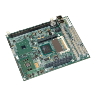
Chapter 2 Product Overview Major Integrated Circuits (Chips) Table 2-1 lists the major integrated circuits, including a brief description of each, on the LittleBoard 800 and Figures 2-3 and 2-4 show the locations of the major integrated circuits (chips). Table 2-1. Major Integrated Circuit Description and Function Chip Type Mfg. - Page 17 Chapter 2 Product Overview PCI-to-ISA Bridge (U41) 10/100 Ethernet (U9) Super I/O-1 Gigabit (U14) Ethernet (U11) Super I/O-2 (U16) Figure 2-4. Component Locations (Bottom view) LittleBoard 800 Reference Manual...
-
Page 18: Connector Definitions
Video (LVDS) 30-pin, 2mm, connector for LVDS type video displays NOTE Ampro uses a connector/header identification method in Chapter 3 to avoid difficult to see visible numbering next to the connectors. For example, a 20-pin header with two rows of pins, using odd/even numbering, where pin-2 is directly across and adjacent to pin-1, is noted in this way;... - Page 19 Chapter 2 Product Overview LVDS (J26) CRT (J3) Audio In/Out (J9) Optional J21) DDR DIMM Slot (DIMM1) Utility 3 (J14) PC/104-Plus (J2) JP19 CompactFlash Socket (J8) Ethernet Port 2 (J10) Ethernet Parallel (J16) Port 1 (J23) Ethernet Floppy (J17) Grounding Board Utility 2 (J13) Grounding...
-
Page 20: Led Definitions
Chapter 2 Product Overview LED Definitions Tables 2-3 and 2-4 provide the LED colors and definitions for the Ethernet ports, Port 1 (J23) and Port 2 (J10) located on the LittleBoard 800. Refer to Figure 2-6. Table 2-3. Ethernet Port 1 (J23) LED Indicators Indicator Definition Ethernet... -
Page 21: Additional Components
Chapter 2 Product Overview CMOS Normal/Clear (JP19) JP19 Serial Port 1 RS485 Termination (JP4) Serial Port 2 CompactFlash RS485 Voltage (JP3) Termination (JP5) Serial Port 3 RS485 Termination (JP6) Serial Port 4 RS485 CompactFlash Termination (JP7) Master/Slave (JP2) Figure 2-7. Jumpers and Fuse Locations (Top view) Additional Components The fuse in Table 2-6 is shown in Figure 2-7. -
Page 22: Specifications
Chapter 2 Product Overview Specifications Physical Specifications Table 2-7 gives the physical dimensions of the board and Figures 2-8 and 2-9 give the mounting dimensions and pin-1 connector locations. Table 2-7. Weight and Footprint Dimensions Item Dimension NOTE Overall height is measured from the upper board surface to the Weight 0.351kg. -
Page 23: Power Specifications
**The BIT (burn in test) current was measured using with 128MB DDR PC2700 RAM, video, Ampro I/O Interface board, floppy (1), IDE HDD (1), PS/2 keyboard & mouse, 4 Serial loopbacks, externally powered USB CD-ROM (1), externally powered USB HDD (1), USB Jump-Drive (1), USB CompactFlash reader with 64MB CompactFlash card (1), onboard 64MB CompactFlash card, and two operating Ethernet channels. -
Page 24: Mechanical Specifications
Chapter 2 Product Overview Mechanical Specifications Figures 2-8 and 2-9 show top views of the LittleBoard 800 with the mechanical mounting dimensions. 7.800 7.600 7.600 7.535 7.225 6.800 6.345 6.350 5.800 5.700 5.350 3.500 3.100 2.700 2.800 2.650 2.200 -0.100 -0.200 Figure 2-8. - Page 25 Chapter 2 Product Overview 7.800 7.600 7.600 7.500 7.150 6.465 5.800 5.700 2.800 2.650 -0.060 -0.200 Figure 2-9. LittleBoard 800 Dimensions (Top view, #2) NOTE All dimensions are given in inches. LittleBoard 800 Reference Manual...
- Page 26 Chapter 2 Product Overview Reference Manual LittleBoard 800...
-
Page 27: Chapter 3 Hardware
Power Interface (J19) NOTE Ampro Computers, Inc. only supports the features/options tested and listed in this manual. The main integrated circuits (chips) used in the LittleBoard 800 may provide more features or options than are listed for the LittleBoard 800, but some of these chip features/options are not supported on the board and may not function as specified in the chip documentation. -
Page 28: Cpu (U1)
Chapter 3 Hardware CPU (U1) The LittleBoard 800 offers high performance Intel processors at 1.4GHz Low Voltage (LV) Pentium® M 738, 1.0GHz Ultra Low Voltage (ULV) Celeron® M 373, or 600MHz Ultra Low Voltage (ULV) Celeron M processor. Celeron M Processors The 600MHz Celeron M processor (Banias core) has 512kB L2 Cache on board, with a 400MHz FSB (front side bus). -
Page 29: Interrupt Channel Assignments
Chapter 3 Hardware Interrupt Channel Assignments The channel interrupt assignments are shown in Table 3-1. Table 3-1. Interrupt Channel Assignments Device vs IRQ No. 10 11 Timer Keyboard Secondary Cascade COM1 COM2 COM3 COM4 Floppy Parallel IDE Primary IDE Secondary Math Coprocessor PS/2 Mouse PCI INTA... -
Page 30: I/O Address Map
Chapter 3 Hardware Table 3-2. Memory Map Base Address Function 00000000h 0009FFFFh Conventional Memory 000A0000h 000AFFFFh Graphics Memory 000B0000h 000B7FFFh Mono Text Memory 000B8000h 000BFFFFh Color Text Memory 000C0000h 000C7FFFh Standard Video BIOS 000F0000h 000FFFFFh System BIOS Area (Storage and RAM Shadowing) 00100000h 04000000h Extended Memory (If onboard VGA is enabled, then the amount... -
Page 31: Pc/104-Plus Interface (J2)
Chapter 3 Hardware PC/104-Plus Interface (J2) PC/104-Plus uses a 120 pin (4x30) 2mm connector interface. This interface connector carries all of the appropriate PCI signals operating at clock speeds up to 33MHz. The Memory Hub (82855GME), integrates a PCI arbiter that supports up to four devices with three external PCI masters. This interface header accepts stackable modules and is located on the top of the board. - Page 32 Chapter 3 Hardware Pin # Signal Input/ Description Output 25 (A25) GNT1* Grant 1 – These signal (GNT 0-2) lines indicate access has been granted to the requesting device (PCI Masters). 26 (A26) +5 volts ±5% power supply input Clock 2 – These clocks (CLK 0-3) provide timing outputs for four 27 (A27) CLK2 external PCI devices and all timing transactions on the PCI bus.
- Page 33 Chapter 3 Hardware Pin # Signal Input/ Description Output 60 (B30) REQ3* Bus Request 3 – Refer to pin-A23 for more information. 61 (C1) +5 volts ±5% power supply input 62 (C2) AD01 Address/Data Bus Line 1 – Refer to pin-A3 for more information. 63 (C3) AD04 Address/Data Bus Lines 4 –...
- Page 34 Chapter 3 Hardware Pin # Signal Input/ Description Output 97 (D7) AD12 Address/Data Bus Line 12 – Refer to pin-A3 for more information. 98 (D8) +3.3V +3.3 volts ±5% power supply input 99 (D9) Bus Parity bit – This signal is the even parity bit on AD[31:0] and C/BE[3:0]* 100 (D10) NC Not connected (Snoop Done)
-
Page 35: Pc/104 Interface (J1A,B,C,D)
Chapter 3 Hardware PC/104 Interface (J1A,B,C,D) The PC/104 Bus uses a 104-pin 100 mil header interface. This interface header will carry all of the appropriate PC/104 signals operating at clock speeds up to 8MHz. This interface header accepts stackable modules and is located on the top of the board. The PC/104 connector uses 104-pin, 4 rows, consecutive numbering, (A1, B1, C0, D0), and 0.100"... -
Page 36: Table 3-6. Pc/104 Interface Pin/Signal Descriptions (J1B)
Chapter 3 Hardware Pin # Signal Description (J1 Row A) 25 (A25) SA6 System Address 6 – Refer to pin-A12 , for more information. 26 (A26) SA5 System Address 5 – Refer to pin-A12 , for more information. 27 (A27) SA4 System Address 4 –... -
Page 37: Table 3-7. Pc/104 Interface Pin/Signal Descriptions (J1C)
Chapter 3 Hardware Pin # Signal Descriptions (J1 Row B) 48 (B16) DRQ3 DMA Request 3 – Used by I/O resources to request DMA service. Must be held high until associated DACK3 line is active. 49 (B17) DACK1* DMA Acknowledge 1 – Used by DMA controller to select the I/O resource requesting the bus, or to request ownership of the bus as a bus master device. -
Page 38: Table 3-8. Pc/104 Interface Pin/Signal Descriptions (J1D)
Chapter 3 Hardware Pin # Signal Descriptions (J1 Row C) 5 (C4) LA21 Latchable Address 21 – Refer to pin-C2, for more information. 6 (C5) LA20 Latchable Address 20 – Refer to pin-C2, for more information. 7 (C6) LA19 Latchable Address 19 – Refer to pin-C2, for more information. 8 (C7) LA18 Latchable Address 18 –... - Page 39 Chapter 3 Hardware Pin # Signal Descriptions (J1 Row D) 31 (D10) DACK5* DMA Acknowledge 5 – Used by DMA controller to select the I/O resource requesting the bus, or to request ownership of the bus as a bus master device.
-
Page 40: Ide Interface (J6, J7)
Chapter 3 Hardware IDE Interface (J6, J7) The LittleBoard 800 provides two IDE connectors for primary and secondary IDE signals. The EIDE interface logic supports the following features: • Bus master IDE transfer rate up to 100Mbps when 80-pin grounded shielded cable is used •... -
Page 41: Table 3-10. Secondary Ide Interface Pin/Signal Descriptions (J7)
Chapter 3 Hardware Pin # Signal Description PDIOW* Primary I/O Read/Write Strobe – Strobe signal for write functions. Negative edge enables data from a register or data port of the drive onto the host data bus. Positive edge latches data at the host. Ground Primary I/O Read/Write Strobe –... - Page 42 Chapter 3 Hardware Pin # Signal Description SDD11 Secondary Disk Data 11 – These signals (0 to 15) provide the disk data signals. SDD3 Secondary Disk Data 3 – These signals (0 to 15) provide the disk data signals. SD12 Secondary Disk Data 12 –...
-
Page 43: Compactflash Socket (J8)
Chapter 3 Hardware Pin # Signal Description SDCS3 Secondary Slave/Master Chip Select 3 – Used to select the host-accessible Command Block Register. Not connected Ground Notes: The shaded area denotes power or ground. The signals marked with * = Negative true logic. CompactFlash Socket (J8) The board contains a Type II PC card socket, which allows for the insertion of a CompactFlash (CF) Card. - Page 44 Chapter 3 Hardware Pin # Signal Description Secondary Disk Data 0 – Refer to SD3 on pin-2 for more information. Secondary Disk Data 1 – Refer to SD3 on pin-2 for more information. Secondary Disk Data 2 – Refer to SD3 on pin-2 for more information. Not used (IOIS16*, connected through 10k ohm resistor to VCC) Not used (CD2*, connected through 10k ohm resistor to VCC) Not used (CD1*, connected through 10k ohm resistor to VCC)
-
Page 45: Floppy Drive Interface (J17)
Chapter 3 Hardware Pin # Signal Description Secondary Disk Data 8 – Refer to SD3 on pin-2 for more information. Secondary Disk Data 9 – Refer to SD3 on pin-2 for more information. SD10 Secondary Disk Data 10 – Refer to SD3 on pin-2 for more information. Ground Notes: The shaded area denotes power or ground. -
Page 46: Parallel Port Interface (J16)
Chapter 3 Hardware Parallel Port Interface (J16) Parallel port supports standard parallel, Bi-directional, ECP and EPP protocols. The LPC47B272 provides separate parallel port interface signals not shared with the floppy drive signals. The parallel connector has 26 pins, 2 rows, odd/even, (1, 2), with 0.100” pin spacing. Table 3-13. -
Page 47: Serial Interfaces (J11, J12)
Chapter 3 Hardware Serial Interfaces (J11, J12) Two LPC47B272 chips provide the circuitry for the 4 serial ports. One chip provides serial ports 1 and 2 through connector J11 and the second chip provides serial ports 3 and 4 through connector J12. The four serial ports support the following features: •... -
Page 48: Table 3-14. Serial A Interface Pin/Signal Descriptions (J11)
Chapter 3 Hardware Table 3-14. Serial A Interface Pin/Signal Descriptions (J11) Pin # Pin # Signal Description DCD1* Data Carrier Detect 1 – Indicates external serial communications device is detecting a carrier signal (i.e., a communication channel is currently (COM1) open). -
Page 49: Table 3-15. Serial B Interface Pin/Signal Descriptions (J12)
Chapter 3 Hardware Pin # Pin # Signal Description CTS2* Clear To Send 2 – Indicates external serial communications device is ready to receive data. Used as hardware handshake with RTS2 for low level flow control. RX2+ RX2+ – If in RS485 or RS422 mode, this pin is Receive Data 2 -. DTR2* Data Terminal Ready 2 –... - Page 50 Chapter 3 Hardware Pin # Pin # Signal Description DCD4* Data Carrier Detect 4 – Indicates external serial communications device (COM4) is detecting a carrier signal (i.e., a communication channel is currently open). In direct connect environments, this input will be driven by DTR4 as part of the DTR/DSR handshake.
-
Page 51: Utility Interfaces
Chapter 3 Hardware Utility Interfaces The Utility interfaces consists of three connectors that provide the standard interface signals for the following devices: • Utility 1 (J15) ♦ Keyboard ♦ External battery connection ♦ Reset Switch ♦ Speaker • Utility 2 (J13) ♦... -
Page 52: Speaker
Chapter 3 Hardware Speaker The signal lines for a speaker port with 0.1-watt drive are provided through a Utility 1 interface (J15). Table 3-16. Utility 1 Interface Pin/Signal Descriptions (J15) Pin # Signal Description -12V -12 Volts – Supplied from external power source. Ground -5 Volts –... -
Page 53: Usb Signals (Usb1 And Usb2)
Over-current detection status (software) on all four USB ports NOTE Ampro does not recommend connecting a USB boot device to the LittleBoard 800 through an external hub. Instead, connect the USB boot device directly to the LittleBoard 800. Refer to Chapter 4, BIOS Setup for more information. -
Page 54: Table 3-18. Utility 2 Interface Pin/Signal Descriptions (J13)
Chapter 3 Hardware Table 3-18. Utility 2 Interface Pin/Signal Descriptions (J13) Pin # Signal Description LIDSW Lid Switch – This signal (Suspend Status on I/O Hub) is asserted by the I/O Hub to indicate the system will be entering a low power state soon. This signal is not shared with other devices on the LittleBoard. -
Page 55: Utility 3 Interface (J14)
Over-current detection status on the USB port (software) NOTE Ampro does not recommend connecting a USB boot device to the LittleBoard 800 through an external hub. Instead, connect the USB boot device directly to the LittleBoard 800. Refer to Chapter 4, BIOS Setup for more information. -
Page 56: Ethernet Interfaces (J10, J23)
Chapter 3 Hardware Ethernet Interfaces (J10, J23) The Ethernet solution is provided by two Intel Ethernet controllers, 82541ER, and (Gigabit) 82541GI/PI for Port 1 and Port 2 respectively. Both controllers consist of a Media Access Controller (MAC) and a physical layer (PHY) combined into a single component solution. 10/100BaseT Ethernet Controller (U9) Ethernet Port 1 uses an Intel 82551ER, 32-bit PCI controller that features enhanced scatter-gather bus mastering capabilities, which enables the 82551ER to perform high-speed data transfers over the PCI... -
Page 57: Gigabit Ethernet Controller (U11)
Chapter 3 Hardware Table 3-20. Ethernet Port 1 Pin/Signal Descriptions (J23) Pin # Signal Description Analog Twisted Pair Ethernet Transmit Differential Pair – These pins transmit the serial bit stream for transmission on the Unshielded Twisted Pair Cable (UTP). These signals interface directly with an isolation transformer. Analog Twisted Pair Ethernet Receive Differential Pair –... -
Page 58: Table 3-21. Ethernet Port 2 Pin/Signal Descriptions (J10)
Chapter 3 Hardware • IEEE 802.3ab Auto-Negotiation support, includes speed, duplex, and flow control • IEEE 802.3ab PHY compliance and compatibility with Category-5 twisted pair cabling • Implements latest DSP architecture with digital adaptive equalization, echo cancellation, and crosstalk cancellation to achieve high performance in noisy environments (high electrical/signal interference impairment) •... -
Page 59: Audio Interface (J9)
Chapter 3 Hardware Audio Interface (J9) The audio solution on the LittleBoard 800 is provided by the Realtek ALC202A audio CODEC. The chip is defined by AC97 and is revision 2.2 compliant. The audio interface signals are supplied to the 26-pin 2mm connector (J9). -
Page 60: Video Interfaces (J3, J26)
Chapter 3 Hardware Video Interfaces (J3, J26) The 855GME chip provides the graphics control and video signals to the traditional glass CRT monitors and LCD flat panel displays. The chip features are listed below: CRT features: • Supports a max resolution of 1600 x 1200 with video frame buffer set at 8MB •... -
Page 61: Lvds Interface (J26)
Chapter 3 Hardware LVDS Interface (J26) Table 3-24 describes the pin-outs and signals of the LVDS interface and it has 30 pins, 2 rows, odd/even, (1, 2) with 2mm pin spacing header. Table 3-24. LVDS Interface Pin/Signal Descriptions (J26) Pin # Signal Description Line Channel... -
Page 62: Miscellaneous
Chapter 3 Hardware Miscellaneous Real Time Clock (RTC) The LittleBoard 800 contains a Real Time Clock (RTC). The BIOS (CMOS) RAM is backed up with a Lithium Battery. If the battery is not present, the BIOS has a battery-free boot option to complete the boot process. -
Page 63: Watchdog Timer
The BIOS implements interrupt 15 function 0C3h to manipulate the WDT. • Watchdog Code examples – Ampro has provided source code examples on the LittleBoard 800 Doc & SW CD-ROM illustrating how to control the WDT. The code examples can be easily copied to your development environment to compile and test the examples, or make any desired changes before compiling. -
Page 64: Power Interfaces
Chapter 3 Hardware Power Interfaces Power Supply Input (J19) The LittleBoard 800 uses five separate voltages on the board, but only one of the voltages is provided externally (+5 volts) through the external connector, which uses a 7-pin vertical header with 0.156” (3.96mm) spacing. -
Page 65: Chapter 4 Bios Setup
This section assumes the user is familiar with BIOS Setup and does not attempt to describe the inner workings of BIOS functions. Refer to the appropriate PC reference manuals for information about the onboard ROM-BIOS software interface. If Ampro has added to or modified the standard functions, these functions will be described. -
Page 66: Accessing Bios Setup (Serial Console)
Chapter 4 BIOS Setup Accessing BIOS Setup (Serial Console) Entering the BIOS Setup, in serial console mode, is very similar to the steps you use to enter BIOS Setup with a VGA display, except the actual keys you use. 1. Set the serial terminal, or the PC with communications software to the following settings: ♦... -
Page 67: Bios Menus
Exit, Saving Changes Exit, Discarding Changes Use Arrow keys to change menu item, use Enter to select menu item (C) Copyright 2005, Ampro Computers, Inc. - http://www.ampro.com Figure 4-1. Opening BIOS Screen NOTE For the most current BIOS Information, refer to the Hardware Release Notes provided as hard copy in the shipping container. -
Page 68: Bios Configuration Screen
(none) Boot 5th (none) Use Arrow keys to change menu item, use Page Up/Down to modify. Esc to exit. (C) Copyright 2005, Ampro Computers, Inc. - http://www.ampro.com Figure 4-2. Modifying Setup Parameters Screen • Date & Time ♦ DATE (dd:mmm:yyyy) – This requires the alpha-numeric entry of the calendar month, day of the month, and all 4 digits of the year, including the century plus year (26 May 2005). -
Page 69: Table 4-2. Floppy Drive Bios Settings
(Floppy A connector, because the Floppy B connector is not available). NOTE Ampro does not recommend connecting a USB boot device to the LittleBoard 800 through an external hub. Instead, connect the USB boot device directly to the LittleBoard 800. - Page 70 Chapter 4 BIOS Setup • Boot Order ♦ Boot 1 – [none], [Drive A], [Drive B], [Drive C], [Drive D], [CDROM], [Alarm], or [Reboot] ♦ Boot 2 – [none], [Drive A], [Drive B], [Drive C], [Drive D], [CDROM], [Alarm], or [Reboot] NOTE The [Alarm] option sounds beeps on the PC speaker and can be listed, like [Reboot], as the last boot device to indicate no bootable...
-
Page 71: User Interface Options
Chapter 4 BIOS Setup NOTE This feature allows you to use any one of the three common formats available for CompactFlash cards without having to re-format the CompactFlash card before you can use it on the LittleBoard 800. The LBA (Logical Block Address) is set as the default format because it can handle larger drives and is the newest format available, but may not be the one used to format your CompactFlash card. -
Page 72: Memory Control Options
♦ Splash Screen – [Disabled] or [Enabled] The Splash Screen is a graphical image displayed as the default (Ampro Splash Screen) or a user customized image on screen. Refer to the Splash Screen Customization topic later in this chapter for instructions on how to customize the splash screen. - Page 73 ∗ If this field is set to [Enabled], any of the bootable USB devices connected to the LittleBoard 800 can be used as a boot device. NOTE Ampro does not recommend connecting a USB boot device to the LittleBoard 800 through an external hub. Instead, connect the USB boot device directly to the LittleBoard 800.
- Page 74 Chapter 4 BIOS Setup ♦ LAN Boot – [Disabled] or [LAN1] This field allows you to boot the system over one of the Ethernet connections (LAN1, J23). Refer to Appendix B, LAN Boot Feature and the BIOS settings for the integrated PXE Boot Agent for more information.
- Page 75 Chapter 4 BIOS Setup ♦ Serial 4 – [Disabled], [3F8h], [2F8h], [3E8h], [2E8h], [260h], [3E0h], [2E0h], [200h], [220h], [228h], [238h], or [338h] This field specifies the base address used for Serial Port 4. • IRQ – [none], [1], [3], [4], [5], [6], [7], [9], [10], [11], [12], [14], or [15] This field specifies the IRQ used for Serial Port 4.
-
Page 76: Video And Flat Panel Options
Chapter 4 BIOS Setup Video and Flat Panel Options • On-Board Video ♦ Framebuffer Size – [Disabled], [1MB], [4MB], [8MB], [16MB], or [32MB] This field specifies the amount of system memory used for the on-board Video Framebuffer. The amount of memory used for the Framebuffer of the on-board Video controller is subtracted from the available system memory. -
Page 77: Pci, Plug N' Play, And Interrupt/Dma Assignments
Chapter 4 BIOS Setup PCI, Plug n' Play, and Interrupt/DMA Assignments • PCI ♦ INTA IRQ – [none], [1], [3], [4], [5], [6], [7], [9], [10], [11], [12], [14], or [15] ♦ INTB IRQ – [none], [1], [3], [4], [5], [6], [7], [9], [10], [11], [12], [14], or [15] ♦... - Page 78 Chapter 4 BIOS Setup ♦ Assign IRQ 6 – [Disabled] or [Enabled] (Typically Floppy Disk) ∗ If this field is set to [Enabled], then the BIOS can assign this IRQ to a Plug and Play adapter. ∗ If another device in the system is using this IRQ, then this field should be set to [Disabled].
- Page 79 Chapter 4 BIOS Setup ♦ Assign DMA 0 – [Disabled] or [Enabled] ∗ If this field is set to [Enabled], then the BIOS can assign this DMA channel to a Plug and Play adapter. ∗ If another device in the system is using this DMA channel, then this field should be set to [Disabled].
-
Page 80: Splash Screen Customization
The user’s image may be customized with any bitmap software editing tool, but must be converted into an acceptable format with the tools (files and utilities) provided by Ampro. If the custom image is not converted with the utilities provided, then the image will not display properly when this field is selected in BIOS Setup. - Page 81 ♦ If you are doubtful about the conversion process, due to the file size, Ampro recommends making a copy of your new splash.bmp, so that you can edit it later if the conversion does not yield a small enough file.
- Page 82 Chapter 4 BIOS Setup Reference Manual LittleBoard 800...
-
Page 83: Appendix A Technical Support
• Ampro Virtual Technician – This is a comprehensive support center designed to meet all your technical needs. This service is free and available 24 hours a day through the Ampro web site at http://ampro.custhelp.com. This includes a searchable database of Frequently Asked Questions, which will help you with the common information requested by most customers. - Page 84 Appendix A Technical Support Reference Manual LittleBoard 800...
-
Page 85: Appendix Blan Boot Feature
PXE works go to, http://www.pxe.ca. For more detailed information concerning pre-OS agents, go to: http://www.pre-OS.com. Ampro provides a third party PXE boot agent integrated into the LittleBoard 800 BIOS, but does not provide the PXE server components. You will also need to provide your own PXE server components on a compatible PXE server, before making full use of the LAN Boot feature. -
Page 86: Pxe Boot Agent Bios Setup
LAN Boot Feature PXE Boot Agent BIOS Setup This section describes the BIOS settings of the third party PXE Boot agent provided by Ampro and integrated into the LittleBoard 800 firmware. The PXE Boot Agent’s BIOS setup menu and screens are used when configuring the LAN boot feature in the LittleBoard 800 BIOS. -
Page 87: Pxe Boot Agent Setup Screen
Appendix B LAN Boot Feature PXE Boot Agent Setup Screen Argon Managed PC Boot Agent (MBA) v4.31 (BIOS integrated) (C) Copyright 2002, Argon Technology Corporation (C) Copyright 2003, 3COM Corporation All rights reserved Configuration Boot Method: Default Boot: Local Local Boot: Enabled Config Message Enabled... - Page 88 Appendix B LAN Boot Feature • NetWare Configuration ♦ Boot Method: – [PXE], [TCP/IP], [NetWare], or [RPL] ♦ Protocol: – [802.2], [802.3], or [EthII] ♦ Default Boot: – [Local] or [Network] ♦ Local Boot: – [Disabled] or [Enabled] ♦ Config Message: – [Disabled] or [Enabled] ♦...
-
Page 89: Appendix C Connector Part Numbers
Note: *The LVDS (J26) part number listed in this table is not the mating connector, but the component used by Ampro to stuff the LittleBoard 800. The LVDS cable provided in QuickStart Kit is an unfinished 25" long cable with one connector, which connects to J26 on the LittleBoard. Refer to this web site (http://www.samtec.com) for mating connector information. - Page 90 Appendix C Connector Part Numbers Reference Manual LittleBoard 800...
-
Page 91: Index
Index Ampro Products boot device CD-ROM............62 CoreModule™ Family ........3 CompactFlash..........62 EnCore™ Family ..........4 floppy disk drive..........62 ETX Family ............4 IDE device setup ..........63 LittleBoard™ 550 ..........3 IDE hard disk drive ......... 62 LittleBoard™ 700 ..........3 LAN Boot............79 MightyBoard™... - Page 92 Index infrared interface Video settings ..........70 supported features ..........47 voltage requirements........58 input and output codes watchdog timer (WDT) ........57 PCI table notes ..........28 weight .............. 16 Interrupt (IRQs) list..........23 see also supported features jumper locations...........14 LVDS interface LAN Boot pin-out list............
- Page 93 Index Serial B (COM3 & 4) on-board CRT fuse .......... 15 pin-out list............43 Oops! jumper (BIOS recovery) ....9, 56 Serial Communications Software......56 Parallel port (1)..........7, 40 Serial console PC/104 bus ..........7, 29 accessing BIOS ..........60 PC/104-Plus ..........7, 25 configuring BIOS Setup........67 PC "Beep"...
- Page 94 Index LittleBoard 800 Reference Manual...
Need help?
Do you have a question about the LittleBoard800 and is the answer not in the manual?
Questions and answers