Table of Contents
Advertisement
Quick Links
P36 Video
WARNING:
If the information in these instructions are not followed exactly, a fi re
or explosion may result causing property damage, personal injury or
loss of life.
FOR YOUR SAFETY
Do not store or use gasoline or other fl ammable vapors and liquids in the
vicinity of this or any other appliance.
Installation and service must be performed by a qualifi ed installer, service
agency or the gas supplier.
Tested by:
918-521d
FPI FIREPLACE PRODUCTS INTERNATIONAL LTD. 6988 Venture St., Delta, BC Canada, V4G 1H4
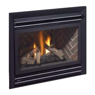
P36 Zero Clearance
Direct Vent Gas Fireplace
MODELS:
P36-NG4 Natural Gas
Installer: Please complete the details on the back cover
and leave this manual with the homeowner.
Homeowner: Please keep these instructions for future reference.
P36-LP4 Propane
Owners & Installation Manual
FOR YOUR SAFETY
What to do if you smell gas:
Do not try to light any appliance
Do not touch any electrical switch: do not
use any phone in your building.
Immediately call your gas supplier from
a neighbour's phone. Follow the gas
supplier's instructions.
If you cannot reach your gas supplier,
call the fi re department.
10/28/13
Advertisement
Table of Contents

Related Manuals for Regency Fireplace Products P36-NG4 Natural Gas


Summary of Contents for Regency Fireplace Products P36-NG4 Natural Gas
- Page 1 P36 Zero Clearance Direct Vent Gas Fireplace MODELS: P36-NG4 Natural Gas P36-LP4 Propane Owners & Installation Manual P36 Video FOR YOUR SAFETY WARNING: What to do if you smell gas: If the information in these instructions are not followed exactly, a fi re ...
- Page 2 To the New Owner: Congratulations! You are the owner of a state-of-the-art Gas Fireplace by FPI FIREPLACE PRODUCTS INTERNATIONAL LTD. The P36 has been designed to provide you with all the warmth and charm of a wood fi replace at the fl ick of a switch. The model P36 has been approved by Warnock Hersey for both safety and effi...
- Page 3 INFORMATION FOR MOBILE/MANUFACTURED HOMES AFTER FIRST SALE This FPI product has been tested and listed by Warnock Hersey as a Vented Gas Fireplace Heater to the following standards: CAN/CGA-2.17-M91, and ANSI Z21.88a-2007/CSA 2.33a-2007. This Direct Vent System Appliance must be installed in accordance with the manufacturer's installation instructions and the Manufactured Home Construction and Safety Standard, Title 24 CFR, Part 3280, or the current Standard of Fire Safety Criteria for Manufactured Home Installations, Sites, and Communities ANSI/NFPA 501A, and with CAN/CSA Z240-MH Mobile Home Standard in Canada.
-
Page 4: Table Of Contents
TABLE OF CONTENTS SAFETY LABEL Vertical Terminations ...........26 Vertical Termination - Co-linear Flex System ....28 Safety Label..............6 Venting Arrangements - Vertical Termination ....29 Direct Vent System (Flex) Installation Procedures ..32 REQUIREMENTS High Elevation .............33 Gas Line Installation ............33 Pilot Adjustment ............34 MA Code - CO Detector..........7 Gas Pipe PressureTesting ...........34 (for the State of Massachusetts only) ......7... - Page 5 TABLE OF CONTENTS Finishing Trim ..............53 PARTS LIST Main Assembly ............54 Burner Assembly & Log Set.........55 Regency ® Flush Front Accessories ......56 WARRANTY Warranty ..............59 FPI P36-4 Zero Clearance Direct Vent Gas Fireplace...
-
Page 6: Safety Label
SAFETY LABEL SAFETY LABEL This is a copy of the label that accompanies each P36 Zero Clearance Direct Vent Gas Fireplace. We have printed a copy of the contents here for your review. The safety label is located on the front inside base of the unit, visible when the bottom louver is open. -
Page 7: Ma Code - Co Detector
INSTALLATION MA Code - CO Detector (for the State of Massachusetts only) 5.08: Modifications to NFPA-54, Chapter 10 (2) Revise 10.8.3 by adding the following additional requirements: (a) For all side wall horizontally vented gas fueled equipment installed in every dwelling, building or structure used in whole or in part for residential purposes, including those owned or operated by the Commonwealth and where the side wall exhaust vent termination is less than seven (7) feet above finished grade in the area of the venting, including but not limited to decks and porches, the following requirements shall be satisfied:... -
Page 8: Unit Dimensions
DIMENSIONS UNIT DIMENSIONS 33-1/4” (838mm) 36” (914mm) 36” (914mm) 12-3/4” (324mm) FPI P36-4 Zero Clearance Direct Vent Gas Fireplace... -
Page 9: Important Message
INSTALLATION IMPORTANT MESSAGE 12) Installation and any repairs to this appliance CLOTHING OR OTHER FLAMMABLE should be done by a qualifi ed service per- SAVE THESE MATERIAL SHOULD NOT BE PLACED son. A professional service person should ON OR NEAR THE APPLIANCE. INSTRUCTIONS be called to inspect this appliance annually. -
Page 10: Locating Your Gas Fireplace
INSTALLATION Before leaving this unit with the customer, the installer must ensure that the appliance is fi ring correctly and operation fully explained to customer. HEATWAVE This includes: DUCT SYSTEM 1) Clocking the appliance to ensure the correct OPTIONAL KIT #946-556 fi... -
Page 11: Clearances
INSTALLATION CLEARANCES The clearances listed below are Minimum distances unless otherwise stated: A major cause of chimney related fi res is failure to maintain required clearances (air space) to combustible materials. It is of the greatest importance that this fi replace and vent system be installed only in accordance with these instructions. Clearance to Combustibles from: Back 0"... -
Page 12: Regency Clearances
INSTALLATION ® REGENCY CLEARANCES Note: No Hearth Required. Clearances for Flush Front & Full Screen Doors TRIPOLI ARCH DOOR CLEARANCES FPI P36-4 Zero Clearance Direct Vent Gas Fireplace... -
Page 13: Regency ® Series Combustible Mantel Clearances
INSTALLATION ® REGENCY SERIES COMBUSTIBLE MANTEL CLEARANCES Because of the extreme heat this fi replace emits, the mantel clearances are critical. Combustible mantel clearances from top of unit are shown in Diagram 1. Note: A non-combustible mantel may be installed at a lower height if the framing is made of metal studs covered with a non-combustible board. -
Page 14: Mantel Leg Clearances
INSTALLATION ® REGENCY SERIES COMBUSTIBLE MANTEL CLEARANCES Because of the extreme heat this fi replace emits, the mantel clearances are critical. Combustible mantel clearances from top of unit are shown in the diagram below. Note: A non-combustible mantel may be installed at a lower height if the framing is made of metal studs covered with a non-combustible board. -
Page 15: Tripoli Arch Door Framing Note
INSTALLATION TRIPOLI ARCH DOOR FRAMING NOTE When installing the optional Tripoli Arch Door, a non-combustible material 12" (305mm) above the unit and 6" (153mm) on each side must be used. See For complete framing dimensions - see page 57 in this manual. diagram 2. -
Page 16: Framing And Finishing
INSTALLATION FRAMING AND FINISHING IMPORTANT FINISHING DETAIL NOTE: 2) Frame in the enclosure for the unit with 3) For exterior walls, insulate the enclosure to When installing tile, carpeting, or any other framing material. The framed opening is the same degree as the rest of the house, 36-1/4"... -
Page 17: Unit Assembly Prior To Installation
INSTALLATION UNIT ASSEMBLY Top Facing Support & "C" Screw Position: Side Nailing Strips For a facing material depth of 1-1/4" (32mm), PRIOR TO the top facing support must be reversed. Determine the total thickness of facing material INSTALLATION (e.g. drywall plus ceramic tiles) to allow the fi... -
Page 18: Exterior Vent Termination Locations
INSTALLATION EXTERIOR VENT TERMINATION LOCATIONS Minimum Clearance Requirements Canada Clearance above grade, veranda, porch, deck, or balcony 12"(30cm) 12"(30cm) Clearance to window or door that may be opened 12"(30cm) 9" (23cm) Clearance to permanently closed window Vertical clearance to ventilated soffi t located above the terminal within a horizontal distance of 2 feet (61cm) 18"(46cm) 18"(46cm) from the center line of the terminal (check with the local code) -
Page 19: Venting
INSTALLATION VENTING DIRECT VENT SYSTEM (FLEX) HORIZONTAL TERMINATIONS ONLY These venting systems, in combination with the P36 Direct Vent Gas Fireplace, have been tested and listed as a direct vent heater system by Warnock Hersey. The location of the termination cap must conform to the requirements in the Vent Terminal Locations diagram in the "Exterior Vent Termination Locations"... -
Page 20: 4" X 6-5/8" Rigid Pipe Cross Reference Chart
INSTALLATION 4” X 6-5/8” RIGID PIPE CROSS REFERENCE CHART Components from different Manufacturers may not be mixed. Not All Rigid Pipe components are available directly from FPI. Description Selkirk American Metal Security ICC Excel Simpson Metal-Fab™ Direct Temp™ Secure- Vent® Direct Direct Vent Pro ®... - Page 21 Never allow the vent to run downward - this could cause high temperatures and may present a possible fi re hazard. Regency Fireplace Products . 6988 Venture St. . Delta, BC . Canada . V4G 1H4 . 604-946-5155 . www.regency-fi re.com...
-
Page 22: Rigid Pipe Venting Systems
INSTALLATION RIGID PIPE VENTING SYSTEMS Horizontal or Vertical Terminations Flat Wall Installation Wall Thickness Vent Length Required The minimum components required for a basic horizontal termination are: (inches) (inches) 4" - 5-1/2" 6" Horizontal Termination Cap Elbow 7" - 8-1/2" 9"... -
Page 23: Rigid Pipe Venting Arrangements
INSTALLATION RIGID PIPE VENTING ARRANGEMENTS HORIZONTAL TERMINATIONS FPI DIRECT VENT SYSTEM (FLEX) (Propane & Natural Gas) The diagram shows all allowable combinations of vertical runs with horizontal terminations, using one 90 elbow (two 45 elbows equal one 90 elbow). Note: Must use optional rigid pipe adaptor (Part # 510-994) when using Rigid Pipe venting systems. All Rigid Pipe Systems 4"... - Page 24 INSTALLATION Horizontal Venting with Two (2) 90 Elbows One 90 elbow = Two 45 elbows. Option H + H1 W i t h t h e s e o p t i o n s , 0' Min. 2' Max. maximum total pipe length 1' Min.
- Page 25 INSTALLATION Vertical Venting with Two (2) 90 Elbows One 90 elbow = Two 45 elbows. Option V + V1 With these options, 0' Min. 2' Max. 1' Min. max. total pipe length 1' Min. 4' Max. 2' Min. is 30 feet with min. of 6 feet total vertical 2' Min.
-
Page 26: Vertical Terminations
INSTALLATION RIGID PIPE VENTING ARRANGEMENTS VERTICAL TERMINATIONS (Propane & Natural Gas) The shaded area in the diagram shows all allowable combinations of straight vertical and offset to vertical terminations, using two 90 elbow, with Rigid Pipe vent systems for Propane and Natural Gas. •... - Page 27 INSTALLATION The P36 is approved for a 40 ft. straight vertical, with rigid pipe vent systems for Propane and Natural Gas, as per the diagram 1. The shaded area in the diagram 1 shows all allowable combinations of straight vertical and offset to vertical terminations with rigid pipe vent systems for Propane and Natural Gas.
-
Page 28: Vertical Termination - Co-Linear Flex System
INSTALLATION VERTICAL TERMINATION - CO-LINEAR FLEX SYSTEM THE APPLIANCE MUST NOT BE Masonry chimneys may take various contours which the fl exible liner will accommodate. However, CONNECTED TO A CHIMNEY FLUE keep the fl exible liner as straight as possible, avoid unnecessary bending. SERVING A SEPARATE SOLID FUEL BURNING APPLIANCE. -
Page 29: Venting Arrangements - Vertical Termination
INSTALLATION VENTING ARRANGEMENTS - VERTICAL TERMINATION with Co-linear Flex System for both Residential & Manufactured Homes into Masonry Fireplaces Horizontal Distance (Feet) The shaded area in the diagrams show the allowable vertical terminations. FPI P36-4 Zero Clearance Direct Vent Gas Fireplace... - Page 30 INSTALLATION b) Horizontal runs of vent must be DURA-VENT HORIZONTAL supported every three feet. Wall straps TERMINATIONS are available for this purpose. Install the vent system according to the 5) Mark the wall for a 10" x 10" square hole. The manufacturer's instructions included with center of the square hole should line up with the components.
- Page 31 INSTALLATION TERMINATIONS elbows. Ensure that all pipes and elbow connections are in the fully twist-locked position and sealed. 1) Maintain the 1-1/4" clearances (air spaces) to combustibles when passing 5) Cut a hole in the roof centered on the small through ceilings, walls, roofs, drilled hole placed in the roof in Step 2.
-
Page 32: Direct Vent System (Flex) Installation Procedures
INSTALLATION 4) Separate the 2 halves of the wall thimble and can result from high wind conditions near big securely fasten the one with the tabs to the trees or adjoining roof lines, in these cases, outside wall making sure that the tabs are increasing the vent height may solve the N o t e : m a k e... -
Page 33: High Elevation
INSTALLATION Note: Output capacity: P36-NG4 System Data The effi ciency rating of the appliance P36-LP4 System Data is a product thermal efficiency For 0 to 4500 feet altitude rating determined under continuous For 0 to 2000 feet altitude Burner Inlet Orifi ce Sizes: #37 operating conditions and was Burner Inlet Orifi... -
Page 34: Pilot Adjustment
INSTALLATION PILOT ADJUSTMENT GAS PIPE PRESSURE S.I.T. VALVE DESCRIPTION TESTING 1) Gas on/off knob Periodically check the pilot fl ames. Correct 2) Manual high/low adjustment fl ame pattern has three strong blue fl ames: The appliance must be isolated from the gas 3) Pilot Adjustment 1 fl... -
Page 35: Conversion From Ng To Lp
INSTALLATION CONVERSION KIT #514-969 FROM NG TO LP FOR P36-4 USING SIT 820 NOVA GAS VALVE THIS CONVERSION MUST BE DONE BY A QUALIFIED GAS FITTER IF IN DOUBT DO NOT DO THIS CONVERSION !! Pull off the pilot cap to expose the pilot For P36D-1 / P36-4 Only: Each Kit contains one LPG orifi... -
Page 36: Installation Of The Dc Sparker
INSTALLATION Reinstall new burner orifi ce LPG 16) Verify that if the conversion is from Installation of the DC Sparker: stamped #52 and tighten. NG to LPG, the screw must be re- assembled with the red o-ring visible 21) Locate the Piezo Ignitor situated at the 10) Turn control knob to the “OFF”... - Page 37 INSTALLATION 25) Locate the ground lug. 28) Install the 1/2" bushing to the heat 32) Mount the heat shield to the DC Sparker. shield. Secure into place with the velcro, which is For P36D-1 / P36-4 Only: provided in the kit. 25a) By the receptical box, left of the unit.
-
Page 38: Optional Brick Panels
INSTALLATION OPTIONAL BRICK PANELS 4) Install the 2 brick retaining clips, one on each side. 1) Undo the bottom 2 door latches and open and remove glass door. Remove logs. Note: The logs must not be in the unit. 2) Insert the back brick panel fi rst by carefully slipping it between the back wall of the fi... -
Page 39: Log Set Installation
INSTALLATION LOG SET INSTALLATION Read the instructions below carefully and refer to the diagrams. If logs are broken do not use the unit until they are replaced. Broken logs can interfere with the pilot operation. The gas log kit (Part # 512-930) contains the following: Place Log 02-49 on the rear log support pins with the fl... - Page 40 INSTALLATION Position Log 02-53 across the cutouts in Logs 02-49 and Sit Log 02-50 on the front left side of the burner. Push the 02-51 with the notch on the left side of the log fi tting into back of the log against the 2 front brackets with the notch the 2nd grate tab.
- Page 41 INSTALLATION 10) Place the embers on the front of the burner tray in the Place Log 02-52 between Logs 02-51 and 02-49 and on places shown on the photo. the indentation on Log 02-54. The bottom right end sits behind the rear grate tab. Separate platinum embers and place on the front burner on and around the embers.
-
Page 42: Standard Flush Door
INSTALLATION STANDARD FLUSH DOOR The standard fl ush door comes with a black frame. To install the frame, Be careful that the glass gasket does not roll up; there must be a gap simply hook the top door fl ange onto the top of the unit and swing the between the gasket and the door lip to ensure that the door sits securely door towards the unit, see Diagram 1. -
Page 43: Remote Control(Optional)
INSTALLATION WALL SWITCH REMOTE CONTROL WALL THERMOSTAT (OPTIONAL) (OPTIONAL) (OPTIONAL) 1) Run the wire through the right or left side A wall thermostat may be installed if desired, Use the FPI Remote Control Kit approved for inlet opening. Be careful not to damage connect the wires as per the wiring diagram. -
Page 44: Wiring Diagrams
INSTALLATION WIRING DIAGRAMS This heater does not require a 120V A.C. sup- NOTE: Even if the fan is not purchased (Do not cut the ground terminal off under ply for operation. In case of a power failure, the with the unit, it is still a good idea to any circumstances.) burner switch and the optional remote control/ bring power to the receptacle box... -
Page 45: Alternate Wiring Diagram For Wall Switch
INSTALLATION ALTERNATE WIRING DIAGRAM FOR WALL SWITCH P36 E lectrical Connec tion Alternative Sc heme " A" , P36 E lectrical Connec tion Alternative Sc heme " B" , P ower at Stove P ower at Switch Wall J unction Box Wall J unction Box *Speed Control *Speed Control... - Page 46 INSTALLATION PROPANE Units and Units Equipped with DC Spark Boxes* *For installation of the DC Spark Box refer to the LP Conversion instructions in this manual. FPI P36-4 Zero Clearance Direct Vent Gas Fireplace...
-
Page 47: Fan Installation (Optional)
INSTALLATION 7) Attach the Fan control box to the Burner 12) Secure the fan wires and power cord by FAN INSTALLATION ON/OFF control box. attaching one of the adhesive backed wire (OPTIONAL) holder clips (Part #910-199) onto the stove base. Use the second clip to bundle up the wires approximately 4"... -
Page 48: Lighting Procedure
OPERATING INSTRUCTIONS LIGHTING FIRST FIRE PROCEDURE The fi rst fi re in your fi replace is part of the paint curing process. To ensure that the paint is properly cured, it is recommended that you IMPORTANT burn your fi replace for at least four (4) hours the To ignite or reignite the pilot, fi... -
Page 49: Copy Of The Lighting Plate Instructions
OPERATING INSTRUCTIONS INSTALLATION MAINTENANCE COPY OF THE LIGHTING PLATE INSTRUCTIONS INSTRUCTIONS 1) Always turn off the gas valve before cleaning. For relighting, refer to lighting instructions. Keep the burner and control compartment clean by brushing and vacuuming at least once a year. When cleaning the logs, use a soft clean paint brush as the logs are fragile and easily damaged. -
Page 50: Log Replacement
MAINTENANCE 3) Check for evidences of excessive condensation, such as water droplets forming GLASS GASKET in the inner liner, and subsequently dripping out the joints, Continuous condensation can If the glass gasket requires replacement use cause corrosion of caps, pipe, and fi ttings. It 5/8"... -
Page 51: Removing Valve
MAINTENANCE 7) Disconnect the inlet gas line. See INSTALLING VALVE REMOVING VALVE Diagram 2. 1) Shut off the gas supply. 1) Attach the valve to the valve bracket with 8) Disconnect the 2 TP wires and the 2 TH the 4 (m5x8 metric) screws provided. wires from the valve. -
Page 52: Flush Louvers
® REGENCY OPTIONS FLUSH LOUVERS 1) Install the top louver by sliding the two bracket clips into the brackets located underneath the top of the fi rebox. 2) The bottom louver has a hinge that is attached (2 screws per hinge) to the lip on bottom of the unit. -
Page 53: Finishing Trim
® REGENCY OPTIONS FINISHING TRIM NOTE: Remove both the Flush Louvers or Bay Louvers and the Flush Front or Bay Front prior to installing the Finishing Trim. 1) Install the Finishing Trim sides as shown in the diagram, line up the holes in the side trim with the holes in the fi rebox side. -
Page 54: Parts List
PARTS LIST MAIN ASSEMBLY Part # Description Part # Description Part # Description 948-045 Chain 31) * Flue Mounting Plate (Optional) 948-025 Spring 42) 910-331/P Fan Motor (120 V) 910-428 Duplex Receptacle 432-966 Fan Switch Assembly 513-901 Brick Panel Set - Standard 910-429 Box - Receptacle (120 Volts) (Optional) -
Page 55: Burner Assembly & Log Set
PARTS LIST BURNER ASSEMBLY & LOG SET Part # Description 513-574/P Valve Assy - Natural Gas 513-576/P Valve Assy - Propane 52) * Valve Tray - NG/LP 53) 430-055 Gasket - Valve Access Plate 54) 910-421 Pilot ON/OFF 3" Extension Knob 55) 910-422 HI/LOW 3"... -
Page 56: Regency ® Flush Front Accessories
PARTS LIST REGENCY ® FLUSH FRONT ACCESSORIES Part # Description Part # Description 132) 512-518 Flush Door Assembly 510-920 Flush Louvers - Gold/Black 157) * Finishing Trim Left 510-922 Flush Louvers - Black 158) * Finishing Trim Top 510-923 Flush Louvers - Steel/Black 159) * Finishing Trim Right ®... - Page 57 NOTES FPI P36-4 Zero Clearance Direct Vent Gas Fireplace...
- Page 58 NOTES FPI P36-4 Zero Clearance Direct Vent Gas Fireplace...
-
Page 59: Warranty
WARRANTY Regency Fireplace Products are designed with reliability and simplicity in mind. In addition, our internal Quality Assurance Team carefully inspects each unit thoroughly before it leaves our facility. FPI Fireplace Products International Ltd. is pleased to extend this limited lifetime warranty to the original purchaser of a Regency Product. - Page 60 ® Register your Regency warranty online www.regency-fi re.com Reasons to register your product online today! • View and modify a list of all your registered products. • Request automatic email notifi cation of new product updates. • Stay informed about the current promotions, events, and special offers on related products.
Need help?
Do you have a question about the P36-NG4 Natural Gas and is the answer not in the manual?
Questions and answers