Table of Contents
Advertisement
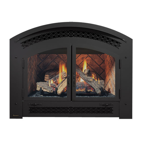
P90 Zero Clearance Direct Vent Gas Fireplace
MODELS:
P90-NG10 Natural Gas
WARNING
FIRE OR EXPLOSION HAZARD
Failure to follow safety warnings exactly could result in serious
injury, death, or property damage.
- Do not store or use gasoline or other flammable vapors and liquids in the vicinity of this or any other
appliance.
- WHAT TO DO IF YOU SMELL GAS
•
Do not try to light any appliance.
• Do not touch any electrical switch: do not use any phone in your building.
Leave the building immediately.
• Immediately call your gas supplier from a neighbour's phone. Follow the gas supplier's
instructions.
• If you cannot reach you gas supplier, call the fire department.
- Installation and service must be performed by a qualified installer, service agency or the gas supplier.
Tested by:
919-495
P90-LP10 Propane
Installer: Please complete the details on the back cover
and leave this manual with the homeowner.
Homeowner: Please keep these instructions for future reference.
REGENCY FIREPLACE PRODUCTS. 6988 Venture St., Delta, BC Canada, V4G 1H4
Owners &
Installation Manual
www.regency-fire.com
06.09.15
Advertisement
Table of Contents

Subscribe to Our Youtube Channel
Related Manuals for Regency Fireplace Products P90-NG10


Summary of Contents for Regency Fireplace Products P90-NG10
- Page 1 - Installation and service must be performed by a qualified installer, service agency or the gas supplier. Tested by: Installer: Please complete the details on the back cover and leave this manual with the homeowner. Homeowner: Please keep these instructions for future reference. 919-495 REGENCY FIREPLACE PRODUCTS. 6988 Venture St., Delta, BC Canada, V4G 1H4 06.09.15...
- Page 2 To the New Owner: Congratulations! You are the owner of a state-of-the-art Excalibur Gas Fireplace by FPI FIREPLACE PRODUCTS ® INTERNATIONAL LTD. The P90 is a hand crafted appliance and has been designed to provide you with all the warmth and charm of a wood fireplace at the flick of a switch. The model P90 has been approved by Warnock Hersey/Intertek for both safety and efficiency.
- Page 3 INFORMATION FOR MOBILE/MANUFACTURED HOMES AFTER FIRST SALE This Excalibur product has been tested and listed by Warnock Hersey as a Direct Vent Wall Furnace to the following standards: VENTED GAS FIREPLACE ® HEATERS ANSI Z21.88-2014/CSA 2.33-2014 and GAS-FIRED APPLIANCES FOR USE AT HIGH ALTITUDES CAN/CGA 2.17-M91. This Direct Vent System Appliance must be installed in accordance with the manufacturer's installation instructions and the Manufactured Home Construction and Safety Standard, Title 24 CFR, Part 3280, or the current Standard of Fire Safety Criteria for Manufactured Home Installations, Sites, and Communities ANSI/NFPA 501A, and with CAN/CSA Z240-MH Mobile Home Standard in Canada.
-
Page 4: Table Of Contents
table of contents Important Message ............8 Gas Line Installation ............32 Before You Start ............8 Pilot Adjustment ............32 General Safety Information..........9 Gas Pipe Pressure Testing ..........32 Installation Checklist ............9 Conversion from NG to LP .........33 Heatwave Duct System Optional Kit ......10 Optional Brick Panels ..........34 Clearances ..............10 Log set Installation............35... - Page 5 dimensions Regency Excalibur P90-10 Zero Clearance Direct Vent Gas Fireplace ®...
-
Page 6: Safety Decal
Tested to: ANSI Z21.88-2014/ CSA 2.33-2014 MAY BE INSTALLED IN MANUFACTURED (MOBILE) HOMES AFTER FIRST SALE. 4001172 NATURAL GAS: Model P90-NG10 APPAREIL FONCTIONNANT AU NATURAL GAZ Minimum Clearances to Combustibles CONCU POUR ETRE POELE: Modéle P90-NG10 /Degagement Minimum De Materiaux Combustibles 5"... -
Page 7: For The State Of Massachusetts Only
requirements MA Code - CO Detector (for the State of Massachusetts only) 5.08: Modifications to NFPA-54, Chapter 10 (2) Revise 10.8.3 by adding the following additional requirements: (a) For all side wall horizontally vented gas fueled equipment installed in every dwelling, building or structure used in whole or in part for residential purposes, including those owned or operated by the Commonwealth and where the side wall exhaust vent termination is less than seven (7) feet above finished grade in the area of the venting, including but not limited to decks and porches, the following requirements shall be satisfied:... -
Page 8: Important Message
IN THE SAME AREA AS THE APPLI- INSTRUCTIONS ANCE. TODDLERS, YOUNG CHILDREN AND OTHERS MAY BE SUSCEPTIBLE The P90-NG10 or P90-LP10 Direct Vent Fireplace TO ACCIDENTAL CONTACT BURNS. A must be installed in accordance with these PHYSICAL BARRIERS IS RECOMMEND- instructions. -
Page 9: General Safety Information
installation GENERAL SAFETY INSTALLATION INFORMATION CHECKLIST 1. The appliance installation must conform with 1. Locate appliance, refer to the following sections: local codes or, in the absence of local codes, with the current Canadian or National Gas a) Locating Your Gas Fireplace Codes, CAN1-B149 or ANSI Z223.1 Installation b) Combustible Mantels Codes. -
Page 10: Heatwave Duct System Optional Kit
installation LOCATING YOUR MANUFACTURED Clearance to Combustibles from: Back 0" (0mm) GAS FIREPLACE MOBILE HOME Side 0" (0mm) ADDITIONAL Floor 0" (0mm) 1. When selecting a location for your fireplace, REQUIREMENTS ensure that the clearances outlined on this page are met. NOTE: The minimum floor clearance must be 1. -
Page 11: Unit Base Stand-Offs
installation FRAMING AND FINISHING UNIT BASE STAND-OFFS 1. Determine the total thickness of facing Insert the 2 unit base stand-offs underneath the To accommodate varying thicknesses and finishes material (e.g. drywall plus ceramic tiles) to of hearth materials, we have increased the overall unit as shown in the diagram below. -
Page 12: Combustible Mantels
installation COMBUSTIBLE MANTELS Because of the extreme heat this fireplace emits, the mantel clearances are critical. Combustible mantel clearances from top of unit are shown in Diagram below. Note: A non-combustible mantel may be installed at a lower height if the framing is made of metal studs covered with a non-combustible board. -
Page 13: Facing Requirement
installation Facing Over 3-3/8" (86mm) Thick 4. Note: The unit does not have to be completely enclosed in a chase. The If the facing material is over 3-3/8" (86mm) thick (example: brick or river clearance on top of the rock), install the facing around the perimeter of the face. You may wish unit is 0"... -
Page 14: Optional Framing Kit
installation OPTIONAL FRAMING KIT An optional framing kit is available to facilitate easier installation of the noncombustible board. The optional framing kit is to be installed within the existing wood framing. The framed opening is 46-1/2" wide x 45-1/4" high or 46-3/8" high if using the base stand- offs and 21-1/2"... -
Page 15: Wall Mount On / Off Switch Installation
installation WALL MOUNT ON / OFF SWITCH AND REMOTE RECEIVER INSTALLATION REQUIRED FOR ALL INSTALLATIONS - INCLUDING PROFLAME REMOTE CONTROLS IMPORTANT INSTALLATION NOTE: The Receiver must be placed inside the supplied (Low Voltage) junction type wall box and installed into the wall only. DO NOT INSTALL WITHIN THE CONFINES OF THE FIREPLACE. -
Page 16: Unit Assembly Prior To Installation
installation UNIT ASSEMBLY VENTING PRIOR TO INTRODUCTION INSTALLATION The P90 uses the "balanced flue" technology Co-axial system. The inner liner vents products The 2 Top Standoffs must be correctly of combustion to the outside while the outer liner positioned and attached to the top before unit draws outside combustion air into the combustion is slipped into position. -
Page 17: Venting
installation VENTING FPI Direct Vent System (Flex) Horizontal Terminations Only These venting systems, in combination with the P90 Direct Vent Gas Fireplace, have been tested and listed as a direct vent heater system by Warnock Hersey/Intertek. The location of the termination cap must conform to the requirements in the Vent Terminal Locations diagram in the "Exterior Vent Termination Locations"... -
Page 18: Exterior Vent Termination Locations
installation EXTERIOR VENT TERMINATION LOCATIONS Minimum Clearance Requirements Canada Clearance above grade, veranda, porch, deck, or balcony 12"(30cm) 12"(30cm) Clearance to window or door that may be opened 12"(30cm) 9" (23cm) Clearance to permanently closed window Vertical clearance to ventilated soffit located above the terminal within a horizontal distance of 2 feet (61cm) 18"(46cm) 18"(46cm) from the center line of the terminal (check with the local code) -
Page 19: 4" X 6-5/8" Rigid Pipe Cross Reference Chart
4DFS SV4BF TM-4CS Trim Plate-Black 4DT-TP 4DFPB 4DcP SV4LA TM-4TP Regency Fireplace Products . 6988 Venture St. . Delta, BC . Canada . V4G 1H4 . 604-946-5155 . www.regency-fi re.com Regency Excalibur P90-10 Zero Clearance Direct Vent Gas Fireplace ®... - Page 20 Never allow the vent to run downward - this could cause high temperatures and may present a possible fi re hazard. Regency Fireplace Products . 6988 Venture St. . Delta, BC . Canada . V4G 1H4 . 604-946-5155 . www.regency-fi re.com...
-
Page 21: 5" X 8" Rigid Pipe Cross Reference Chart
58DVA-FS 5DT-FS 5DFS TM-5LS Trim Plate-Black 58DAV-WFS 5DT-TP 5DCP TM-5TP Regency Fireplace Products . 6988 Venture St. . Delta, BC . Canada . V4G 1H4 . 604-946-5155 . www.regency-fi re.com Regency Excalibur P90-10 Zero Clearance Direct Vent Gas Fireplace ®... - Page 22 fi re hazard. 48” (1219mm) 38-1/4” (972mm) 47-7/8” (1216mm) 22 | Regency Excalibur P90-10 Zero Clearance Direct Vent Gas Fireplace ® Regency Fireplace Products . 6988 Venture St. . Delta, BC . Canada . V4G 1H4 . 604-946-5155 . www.regency-fi re.com...
-
Page 23: Rigid Pipe Venting Systems
installation RIGID PIPE VENTING SYSTEMS The minimum components required for a basic horizontal termination are: Flat Wall Installation Wall Thickness Vent Length Required Horizontal Termination Cap (inches) (inches) Elbow Rigid Pipe Adaptor 4" - 5-1/2" 6" Wall Thimble 7" - 8-1/2" 9"... - Page 24 installation Horizontal & Vertical Terminations for 5" x 8" Venting 24 | Regency Excalibur P90-10 Zero Clearance Direct Vent Gas Fireplace ®...
-
Page 25: Rigid Pipe Venting Arrangements - Horizontal Terminations
installation RIGID PIPE VENTING ARRANGEMENTS - HORIZONTAL TERMINATIONS FPI DIRECT VENT SYSTEM (FLEX) (Propane & Natural Gas) The diagram shows all allowable combinations of vertical runs with horizontal terminations, using one 90 elbow (two 45 elbows equal one 90 elbow). All Rigid Pipe Systems All Rigid Pipe Systems 4"... -
Page 26: Rigid Pipe Venting Arrangements - Vertical Terminations
installation RIGID PIPE VENTING ARRANGEMENTS - The P90 is approved for a maximum 40 ft. straight vertical, with rigid pipe 4" x 6-5/8" vent systems for Propane and Natural Gas, as per diagram. VERTICAL TERMINATIONS The shaded area in the diagram show all allowable combinations of straight vertical and offset to vertical terminations with rigid pipe vent systems for Propane and Natural Gas. - Page 27 installation Horizontal Venting with Two (2. 90 Elbows Must Use: 5" x 8" Simpson Direct Vent Piping with FPI Increaser Starter Collar (Part #946-605.. One 90 elbow = Two 45 elbows. Option H + H1 W i t h t h e s e o p t i o n s , maximum total pipe length 6"...
- Page 28 installation Vertical Venting with Two (2. 90 Elbows Must Use: 5" x 8" Simpson Direct Vent Piping with FPI Increaser Starter Collar (Part #946-605., unless V1 is greater than or equal to 4'-6" then use 4" x 6-5/8" piping. One 90 elbow = Two 45 elbows.
-
Page 29: Horizontal Terminations
installation HORIZONTAL b) Horizontal runs of vent must be supported every three feet. Wall straps TERMINATIONS are available for this purpose. Install the vent system according to the 5. Mark the wall for a 10" x 10" square hole. manufacturer's instructions included with The center of the square hole should line the components. -
Page 30: Vertical Terminations
installation VERTICAL TERMINATIONS 4. Assemble the desired lengths of pipe and elbows. Ensure that all pipes and elbow connections are in the fully twist-locked position and sealed. 1. M a i n t a i n t h e 1 - 1 / 2 " clearances (air spaces) to 5. -
Page 31: Installation Procedures
installation Note: To make the the vertical height must be increased. A poor draft, or down drafting can result from high i n s t a l l a t i o n m o r e 4. Separate the 2 halves of the wall thimble and wind conditions near big trees or adjoining aesthetically pleasing, securely fasten the one with the tabs to the... -
Page 32: High Elevation
When using copper or flex connectors use only The manifold pressure is controlled by a regulator P90-NG10 System Data approved fittings. Always provide a union so built into the gas control, and should be checked that gas lines can be easily disconnected for at the pressure test point. -
Page 33: Conversion From Ng To Lp
installation Conversion from NG to LPG using SIT 829 NOVA Gas Valve CONVERSION FROM NG TO LP THIS CONVERSION MUST BE DONE BY A QUALIFIED GAS FITTER THIS CONVERSION MUST BE DONE BY A QUALIFIED GAS FITTER IF IN DOUBT DO NOT DO THIS CONVERSION !! IF IN DOUBT DO NOT DO THIS CONVERSION!! Remove pilot clip below pilot cap. -
Page 34: Optional Brick Panels
installation OPTIONAL BRICK PANELS 1. Remove Arch Surround, if already installed. 5. Install the 2 brick retaining clips, one on each side. 2. Remove glass door. Remove logs. Note: The logs must not be in the unit. 3. Insert the back brick panel first by carefully slipping it between the back wall of the firebox and the rear log bracket. -
Page 35: Log Set Installation
installation P36D / P90 LOG SET INSTALLATION LOG SET INSTALLATION Read the instructions below carefully and refer to the Place the Log 02-75 on the rear log support pins with the diagrams. If logs are broken do not use the unit until fl... - Page 36 installation P36D / P90 Position Log 02-53 across the cutouts in Logs 02-75 and 02-51 with the notch on the left side of the log fi tting into the 2nd grate tab. 02-53 02-75 5th Grate Tab 02-51 Place the bottom left front edge of Log 02-55 against the rear bracket on the burner tray and rest the log on the cutout on Log 02-53.
- Page 37 installation P36D / P90 Place Log 02-52 between Logs 02-51 and 02-75 and on Sit Log 02-50 on the front left side of the burner. Push the indentation on Log 02-54. The bottom right end sits the back of the log against the 2 front brackets with the behind the rear grate tab.
- Page 38 installation P36D / P90 10) Place the embers on the front of the burner tray in the 02-51 places shown on the photos below. 02-54 Separate platinum embers and place on the front burner on and around the embers. Avoid stacking platinum embers. Platinum embers may be placed over burner ports.
-
Page 39: Glass Door Installation
installation GLASS DOOR ARCH SURROUND AND SAFETY SCREEN INSTALLATION INSTALLATION 1. Lift Arch Surround /Safety Screen, hook lower tabs on surround into lower slots on bracket within unit–as shown in diagram below. 1. Fit top door bracket over the flange at the top of the firebox. -
Page 40: Wiring Diagrams
installation WIRING DIAGRAMS This heater does not require a 120V A.C. supply for operation. In case of a power failure, the remote control/thermostat will continue to operate. However, a 120V A.C. power supply is needed for the fan/blower operation. (Do not cut the ground terminal off under any circumstances.) NOTE: Even if the fan is not purchased with the unit, it is still a good idea to bring power to the receptacle box (provided with the unit) in case the fan is installed at a later date. -
Page 41: Aeration Adjustment
operating instructions AERATION ADJUSTMENT The air shutter can be adjusted by moving the adjusting wire up or down. The wire is accessed through the bottom louver opening. Open the air shutter for a blue flame or close for a more yellow flame. -
Page 42: Operating Instructions
operating instructions SHUTDOWN OPERATING LIGHTING PROCEDURE INSTRUCTIONS PROCEDURE 1. Press "OFF" on the remote or slide receiver 1. Read and understand these instructions IMPORTANT switch from remote to "OFF". before operating this appliance. Prior to igniting or re igniting the pilot, remove the glass 2. -
Page 43: Normal Operating Sounds Of Gas Appliances
operating instructions COPY OF THE LIGHTING PLATE INSTRUCTIONS NORMAL OPERATING SOUNDS OF GAS APPLIANCES FOR YOUR SAFETY READ BEFORE LIGHTING This appliance must be installed in accordance with local codes, if any; It is possible that you will hear some sounds if none, follow the National Fuel Gas Code, ANSI Z223.1/NFPA 54, or Natural Gas and Propane Installation Codes, CSA B149.1. -
Page 44: Maintenance Instructions
maintenance MAINTENANCE in the inner liner, and subsequently dripping GLASS GASKET out the joints, Continuous condensation can INSTRUCTIONS cause corrosion of caps, pipe, and fittings. It If the glass gasket requires replacement use a may be caused by having excessive lateral tadpole glass gasket (Part # 936-155.. -
Page 45: Fan Maintenance
maintenance FAN MAINTENANCE 120 Volt AC power is needed for the fan. The fan can be hard wired if desired. The outlet should be To Remove the Fan installed in the receptacle box on the left hand side by a qualified electrician. The neutral (wider) slot of 1. -
Page 46: Removing Valve
maintenance REMOVING VALVE INSTALLING VALVE 1. Shut off electrical and gas supply. 1. Attach the valve to the valve bracket with the 4 (m5x8 metric) screws provided. 2. Remove the facade if installed. 2. Reconnect the "gas out" flare fitting with an 3. -
Page 47: Main Assembly
parts list MAIN ASSEMBLY Part # Description Part # Description Part # Description 430-129 Receptacle Box Mount 43. 911-159 Power Cord (120 Volts) Thermodisc Bracket 946-570 Heat Release Duct Kit 50. 510-994 Rigid Pipe Adaptor (Optional) 910-428 Duplex Receptacle (Optional) 910-429 Box - Receptacle 51. -
Page 48: Parts List
parts list 48 | Regency Excalibur P90-10 Zero Clearance Direct Vent Gas Fireplace ®... -
Page 49: Burner Assembly & Log Set
parts list BURNER ASSEMBLY & LOG SET Part # Description 53. 780-021 Gasket - Valve Access Plate 792-574/P Valve Assy - Natural Gas 792-576/P Valve Assy - Propane 56. * Valve Tray - NG/LP 57. 910-578 Valve - S.I.T. - NG 910-580 Valve - S.I.T. -
Page 50: Arch Surround And Safety Screen Assembly
parts list ARCH SURROUND AND SAFETY SCREEN ASSEMBLY Part # Description 792-137 Flush door frame 940-326/P Flush glass 936-155 Glass Gasket (tadpole) 792-920 Arch surround with safety screen 792-950 Black Double doors 50 | Regency Excalibur P90-10 Zero Clearance Direct Vent Gas Fireplace ®... -
Page 51: Warranty
Regency Fireplace Products are designed with reliability and simplicity in mind. In addition, our internal Quality Assurance Team carefully inspects each unit thoroughly before it leaves our facility. FPI Fireplace Products International Ltd. is pleased to extend this limited lifetime warranty to the original purchaser of a Excalibur Product. - Page 52 Register your Regency warranty online ® www.regency-fire.com Reasons to register your product online today! • View and modify a list of all your registered products. • Request automatic email notification of new product updates. • Stay informed about the current promotions, events, and special offers on related products.
Need help?
Do you have a question about the P90-NG10 and is the answer not in the manual?
Questions and answers