Table of Contents
Advertisement
Quick Links
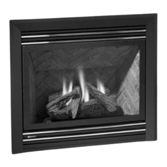
Direct Vent Gas Fireplace
WARNING:
If the information in these instructions are not followed exactly,
a fi re or explosion may result causing property damage,
personal injury or loss of life.
FOR YOUR SAFETY
Do not store or use gasoline or other fl ammable vapors and
liquids in the vicinity of this or any other appliance.
Installation and service must be performed by a qualifi ed
installer, service agency or the gas supplier.
Tested by:
918-520b
FPI FIREPLACE PRODUCTS INTERNATIONAL LTD.
P33-4 Zero Clearance
MODELS:
P33-NG4 Natural Gas
Installer: Please complete the details on the back cover
and leave this manual with the homeowner.
Homeowner: Please keep these instructions for future reference.
P33-LP4 Propane
FOR YOUR SAFETY
What to do if you smell gas:
Do not try to light any appliance
Do not touch any electrical switch:
do not use any phone in your
building.
Immediately call your gas supplier
from a neighbour's phone. Follow
the gas supplier's instructions.
If you cannot reach your gas
supplier, call the fi re department.
6988 Venture St., Delta, BC Canada, V4G 1H4
Owners &
Installation Manual
www.regency-fi re.com
02/26/09
Advertisement
Table of Contents

Subscribe to Our Youtube Channel
Related Manuals for Regency Fireplace Products P33-NG4


Summary of Contents for Regency Fireplace Products P33-NG4
- Page 1 P33-4 Zero Clearance Owners & Installation Manual Direct Vent Gas Fireplace www.regency-fi re.com MODELS: P33-NG4 Natural Gas P33-LP4 Propane WARNING: FOR YOUR SAFETY If the information in these instructions are not followed exactly, What to do if you smell gas: ...
- Page 2 WARNING HOT GLASS WILL CAUSE BURNS DO NOT TOUCH GLASS UNTIL COOLED NEVER ALLOW CHILDREN TO TOUCH GLASS CHILDREN AND ADULTS SHOULD BE ALERTED TO THE HAZARDS OF HIGH SURFACE TEMPERATURES, ESPECIALLY THE FIREPLACE GLASS, AND SHOULD STAY AWAY TO AVOID BURNS OR CLOTHING IGNITION.
- Page 3 To the New Owner: Congratulations! You are the owner of a state-of-the-art Gas Fireplace by FPI FIREPLACE PRODUCTS INTERNATIONAL LTD. The P33-4 has been designed to provide you with all the warmth and charm of a wood fi replace at the fl ick of a switch. The P33-4 has been approved by Warnock Hersey/Intertek for both safety and effi...
-
Page 4: Table Of Contents
TABLE OF CONTENTS Double Screen Door ...........38 SAFETY LABEL Optional Bay Door ............38 Optional Bay Trim ............38 Safety Label..............4 Flush Louvers .............38 Bay Louvers..............39 REQUIREMENTS Full Screen doors ............40 Contemporary Faceplate Installation Part 1 ....42 MA Code - CO Detector ..........5 Contemporary Faceplate Installation Part 2 ....43 Contemporary Faceplate Installation Part 3 ....44 INSTALLATION... -
Page 5: Safety Label
SAFETY LABEL SAFETY LABEL This is a copy of the label that accompanies each P33-4 Zero Clearance Direct Vent Gas Fireplace. We have printed a copy of the contents here for your review. The safety label is located on the front inside base of the unit, visible when the bottom louver is open. -
Page 6: Requirements
REQUIREMENTS MA Code - CO Detector (for the State of Massachusetts only) 5.08: Modifications to NFPA-54, Chapter 10 (2) Revise 10.8.3 by adding the following additional requirements: (a) For all side wall horizontally vented gas fueled equipment installed in every dwelling, building or structure used in whole or in part for residential purposes, including those owned or operated by the Commonwealth and where the side wall exhaust vent termination is less than seven (7) feet above finished grade in the area of the venting, including but not limited to decks and porches, the following requirements shall be satisfied:... -
Page 7: Installation
TEMPERATURES, ESPECIALLY 8) To prevent injury, do not allow anyone who The P33-NG4 or P33-LP4 Direct Vent Fireplace T H E F I R E P L A C E G L A S S , must be installed in accordance with these is unfamiliar with the operation to use the instructions. -
Page 8: Installation Checklist
INSTALLATION INSTALLATION LOCATING YOUR CHECKLIST FIREPLACE 1) Locate appliance a) Room location 1) When selecting a location for your fi replace, (Refer to "Locating Your Fireplace" ensure that the clearances outlined on this DUCT SYSTEM OPTION Section) page are met. b) Clearances to Combustibles Kit #946-556 (Refer to "Clearances"... -
Page 9: Unit Dimensions
INSTALLATION UNIT DIMENSIONS UNIT DIMENSIONS WITH CONTEMPORARY FACEPLATE 23"(584mm) 33"(838mm) 33"(838mm) 12-3/4"(324mm) ® Regency P33-4 Zero Clearance Direct Vent Gas Fireplace... -
Page 10: Clearances For Bay Or Flush Front
INSTALLATION CLEARANCES FOR BAY OR FLUSH FRONT The clearances listed below are Minimum Minimum Clearance from Top of Unit to: distances unless otherwise stated: Mantel* min. 7" (177mm) Ceiling 30" (762mm) A major cause of chimney related fi res is from top of unit. -
Page 11: Combustible Mantels
INSTALLATION COMBUSTIBLE MANTELS Because of the extreme heat this fi replace emits, the mantel clearances are critical. Combustible mantel clearances from top of unit are shown in the diagram below. Note: A non-combustible mantel may be installed at a lower height if the framing is made of metal studs covered with a non-combustible board. -
Page 12: Mantel Leg Clearances With Flush Or Bay Glass
INSTALLATION MANTEL LEG CLEARANCES WITH FLUSH OR BAY GLASS Combustible mantel leg clearances from side of unit as per diagram: Maximum 1-1/2" projection at 2" minimum clearance. MANTEL LEG CLEARANCES WITH CONTEMPORARY FACEPLATE Combustible mantel leg clearances from side of unit as per diagram: ®... -
Page 13: Framing And Finishing
INSTALLATION FRAMING AND FINISHING 1) Determine the total thickness of facing Rigid Vent Rear Termination material (e.g. drywall plus ceramic tiles) to Minimum Clearances allow the fi nished surface to be fl ush with For Rigid Vent the front of the unit. Total facing thickness can vary from 1/2"... -
Page 14: Framing Dimensions With Contemporary Faceplate
INSTALLATION FRAMING DIMENSIONS WITH CONTEMPORARY FACEPLATE Top Header Wood, drywall or other facing 10" (254mm) dia. Hole through wall Vent. NOTE: If this is an outside corner, the minimum distance between the vent and the outside corner is 6" (15cm) with AstroCap termination cap or 12"... -
Page 15: Framing & Finishing With Contemporary Faceplate
fl ame package, carbon, blue fl ames etc. These are not product related issues. Important: If the Contemporary Faceplate is used on the P33-NG4/P33- LP4 Gas Fireplace, the burner orifi ce (Both NG/LP supplied in this package) must be replaced and an overlay decal (also supplied with kit) must be affi... -
Page 16: Unit Assembly Prior To Installation
INSTALLATION UNIT ASSEMBLY PRIOR TO INSTALLATION The Top Facing Support, the Side Nailing Strips Top Facing Support & and the 2 Top Standoffs must be correctly Side Nailing Strips positioned and attached to the top before the unit is put into position. Determine the total thickness of facing material (e.g. -
Page 17: Exterior Vent Termination Locations
INSTALLATION EXTERIOR VENT TERMINATION LOCATIONS Minimum Clearance Requirements Canada Clearance above grade, veranda, porch, deck, or balcony 12"(30cm) 12"(30cm) Clearance to window or door that may be opened 12"(30cm) 9" (23cm) Clearance to permanently closed window Vertical clearance to ventilated soffi t located above the terminal within a horizontal distance of 2 feet (61cm) 18"(46cm) 18"(46cm) Clearance to unventilated soffi t... -
Page 18: Regency ® Direct Vent Fl Ex System
AstroCap can be replaced with the FPI Riser Vent Termination Cap or the Dura-Vent Snorkel Termination Cap. Note: for P33-NG4 with contemporary faceplate - unit must be raised by 1". ® Regency P33-4 Zero Clearance Direct Vent Gas Fireplace... -
Page 19: Installation Procedures
INSTALLATION INSTALLATION PROCEDURES for Regency ® Direct Vent System (Flex) *If this is an outside corner, the minimum distance between the vent and the outside 1) Locate the unit in the framing, rough in the corner is 6" (15cm) with AstroCap termination cap or 12" (30cm) with Dura-Vent gas (preferably on the right side of the unit) and the electrical (Junction block is on the termination cap. -
Page 20: Rigid Pipe Venting Systems
INSTALLATION RIGID PIPE VENTING SYSTEMS Horizontal or Vertical Terminations The minimum components required for a basic horizontal termination are: AstroCap Horizontal Termination Cap Elbow Rigid Pipe Adaptor Wall Thimble Length of pipe to suit wall thickness (see chart) For siding other than vinyl furring strips may be used, instead of the vinyl siding standoff, to create a level surface to mount the vent terminal. -
Page 21: 4" X 6-5/8" Rigid Pipe Cross Reference Chart
INSTALLATION 4” X 6-5/8” RIGID PIPE CROSS REFERENCE CHART Components from different Manufacturers may not be mixed. Not All Rigid Pipe components are available directly from FPI. 4” X 6- 5/8” RIGID PIPE CROSS REFERENCE CHART Components from different Manufacturers may not be mixed. Not all rigid pipe components are available directly from Regency. Description Selkirk American Metal... - Page 22 INSTALLATION Description Selkirk American Metal Security ICC Excel Simpson Metal-Fab™ Direct Temp™ Secure- Vent® Direct ® Products® Direct Vent Pro Sure Seal Amerivent Direct Attic Insulation Shield 12” 46DVA-IS 4DAIS12 SV4RSA N/A@ FPI Attic Insulation Shield - 36” 4DAIS12 TM-4AS Cold Climates Basic Horizontal Termination Kit (A) Disc.
-
Page 23: Rigid Pipe Venting Arrangements
INSTALLATION RIGID PIPE VENTING ARRANGEMENTS Vertical Terminations (Propane & Natural Gas) The shaded area in the diagram shows all allowable combinations of straight vertical and offset to vertical terminations, using one 90 elbow, with rigid pipe vent systems for Propane and Natural Gas. •... - Page 24 INSTALLATION The P33-4 is approved for a maximum 40 ft. straight vertical, with rigid pipe vent systems for Propane and Natural Gas. The shaded area in the diagram shows all allowable combinations of straight vertical and offset to vertical terminations with rigid pipe vent systems for Propane and Natural Gas.
-
Page 25: Horizontal Terminations
INSTALLATION RIGID PIPE VENTING ARRANGEMENTS Horizontal Terminations REGENCY ® DIRECT VENT SYSTEM (FLEX) (Propane & Natural Gas) This diagram shows all allowable combinations of vertical runs with horizontal terminations, using one 45 and one 90 elbow (two 45 elbows equal one 90 elbow). - Page 26 INSTALLATION Horizontal Venting with Two (2) 90 Elbows Horizontal Venting with Three (3) 90 Elbows One 90 elbow = Two 45 elbows. One 90 elbow = Two 45 elbows. Option H + H1 With these options, maximum Option H + H1 + H2 With these options, maximum total pipe total pipe length is 30 feet...
- Page 27 INSTALLATION Horizontal Venting with Three (3) 90 Elbows One 90 elbow = Two 45 elbows. Option V + V1 H + H1 With these options, maximum total pipe 2' Min. 1' Max. 3' Min. 4' Max. length is 30 feet with minimum of 12 feet 3' Min.
- Page 28 INSTALLATION Vertical Venting with Three (3) 90 Elbows One 90 elbow = Two 45 elbows. Option H + H1 V + V1 With these options, max. total 1' Max. 1' Min. 3' Max. 3' Min. pipe length is 30 feet with min. 2' Max.
-
Page 29: Vertical Termination With Co-Linear Flex System
INSTALLATION VERTICAL TERMINATION WITH CO-LINEAR FLEX SYSTEM Masonry chimneys may take various contours which the fl exible liner will accommodate. However, THE APPLIANCE MUST NOT BE keep the fl exible liner as straight as possible, avoid unnecessary bending. CONNECTED TO A CHIMNEY FLUE SERVING A SEPARATE SOLID FUEL The Air Intake pipe must be attached to the inlet air collar of the termination cap. -
Page 30: Venting Arrangements - Vertical Terminations
INSTALLATION VENTING ARRANGEMENTS - VERTICAL TERMINATIONS with Co-linear Flex System for both Residential & Manufactured Homes into Masonry Fireplaces Horizontal Distance (Feet) When using Contemporary Faceplate, unit must be raised 1". The shaded area in the diagrams show the allowable vertical terminations. ®... -
Page 31: Unit Installation With Horizontal Termination
INSTALLATION UNIT INSTALLATION WITH HORIZONTAL TERMINATION Install the vent system according to the b) Horizontal runs of vent must be Riser Vent Diagram 2a supported every three feet. Wall straps manufacturer's instructions included with the Termination are available for this purpose. components. -
Page 32: Unit Installation With Vertical Termination
INSTALLATION 8) Slide the appliance and vent assembly 4) Assemble the desired lengths of pipe and towards the wall carefully inserting the elbows. Ensure that all pipes and elbow vent pipe into the vent cap assembly. It is connections are in the fully twist-locked important that the vent pipe extends into the position and sealed. -
Page 33: Pilot Adjustment
INSTALLATION PILOT ADJUSTMENT GAS PIPE PRESSURE P33-NG4 System Data TESTING Periodically check the pilot fl ames. Correct With Flush or Bay Glass: fl ame pattern has three strong blue fl ames: The appliance must be isolated from the gas 1 fl owing around the thermopile, 1 around... -
Page 34: Conversion From Ng To Lp
INSTALLATION CONVERSION KIT# 434-969 FROM NG TO LP For P33-4 Using SIT 820 NOVA Gas Valve THIS CONVERSION MUST BE DONE BY A QUALIFIED GAS FITTER IF IN DOUBT DO NOT DO THIS CONVERSION !! NOTE: See page 1 for H25 / H27 conversion instructions and page 7 for E33S / U32S conversion instructions. Unscrew the pilot orifi... - Page 35 INSTALLATION Turn control knob to the “OFF” position. 12) Using the Allen wrench as shown in 15) See Page 35 for DC Sparker installation. Fig.4, rotate the screw clockwise until snug, do not overtighten. Remove the black protection cap by 16) Attach the label "This unit has been hand from the high-low knob (Fig.1).
-
Page 36: Installation Of The Dc Sparker
INSTALLATION 11) Install the supplied battery into the DC Installation of the DC Sparker Connect one end of the supplied green Sparker Box by opening the battery ground wire to the lug with the nut and compartment. washer from the kit. Locate the Piezo Ignitor situated at the NOTE: The battery in the DC Sparker side of valve. -
Page 37: Optional Brick Panels
INSTALLATION OPTIONAL BRICK LOG SET INSTALLATION PANELS D) 251 A) 250 Read the instructions below carefully 1) Undo the bottom 2 door latches and open and refer to the diagrams. If logs and remove glass door. Remove logs. are broken do not use the unit until they are replaced. -
Page 38: Standard Flush Door
INSTALLATION 8) Pull off ember size pieces of rock wool and gently place them on the front of the burner tray in the places shown in the photo below. Do not compress the rock wool, leave it loose. Separate platinum embers and place them on the front of the burner on and around the rock wool. -
Page 39: Double Screen Door
INSTALLATION DOUBLE SCREEN FLUSH LOUVERS DOOR 1) Install the top louver by sliding the two bracket clips into the brackets located 1) Pull out the top louver. underneath the top of the fi rebox. 2) Center the screen door and hook over the 2) Install the bottom louver by folding the louver fl... -
Page 40: Bay Louvers
INSTALLATION BAY LOUVERS 1) Remove fl ush louver top heat shield by removing the 4 screws. 4) Install bottom louver by sliding the two bracket clips into the brackets located underneath the bay door. Secure with 1 screw into each Bottom Louver Mounting Bracket as per diagram below. -
Page 41: Full Screen Doors
INSTALLATION FULL SCREEN DOORS 1) Before beginning the installation, remove the Glass Door from the 4) a) Before attaching the Full Screen Door Frame to the unit, unit. Refer to the manual for instructions. loosen the left and right side #8 Self Tapping Philips screws located on the inside top of the outer frame of the appliance. - Page 42 INSTALLATION NOTE: Should the fi nished wall protrude beyond the face of the unit, 8) Re-install Glass Door. Refer to the manual for instructions. you can accommodate up to 1/2" depth. 9) Slide the Top Grill into the louver brackets located on the inside top of the fi...
-
Page 43: Contemporary Faceplate Installation Part 1
INSTALLATION CONTEMPORARY FACEPLATE INSTALLATION PART 1 DERATING TO LOWER BTU RATING) THIS CONVERSION MUST BE DONE BY A QUALIFIED GAS FITTER IF IN DOUBT DO NOT DO THIS CONVERSION !! 1) Shut off the gas supply. Contemporary Faceplate Derating Kit Contains: Qty. -
Page 44: Contemporary Faceplate Installation Part 2
INSTALLATION CONTEMPORARY FACEPLATE INSTALLATION PART 2 CONTROL MOUNTING PLATE INSTALLATION (FOR P33-4 UNIT WITH FACEPLATE ONLY) 1) Remove top and bottom louvers. 2) Remove ON/OFF switch (for P33-4) from the bottom louver. 3) Attach ON/OFF switch to control mounting plate with one screw as shown below. -
Page 45: Contemporary Faceplate Installation Part 3
INSTALLATION CONTEMPORARY FACEPLATE INSTALLATION PART 3 3) Loosen 4 phillips head screws located inside fi rebox, for screw locations Faceplate see Diagram 4. Install mounting frame and retighten screws. 434-033 Mounting Plate 434-514 Faceplate Support 434-032 Control Shield 434-018F Heat Defl ector 434-516 Faceplate - Black 434-516BL... - Page 46 INSTALLATION 6) Hook the fl ange on the faceplate over the top of the fl ush door and gently lower the faceplate into place until it rests against the faceplate supports as shown in Diagrams 7 & 8. Diagram 7 Faceplate Diagram 8 Faceplate Support...
-
Page 47: Optional Wall Thermostat
INSTALLATION Optional Optional Optional WALL THERMOSTAT REMOTE CONTROL WALL SWITCH Use the Regency ® Remote Control Kit approved 1) Run the supplied 15' of wire through the A wall thermostat may be installed if desired, for this unit. Use of other systems may void right or left side gas inlet opening. -
Page 48: Wiring Diagrams
INSTALLATION WIRING DIAGRAMS This heater does not require a 120V A.C. supply for operation. In case of a power failure, the burner switch and the optional remote control/thermostat will continue to operate. However, a 120V A.C. power supply is needed for the fan/blower operation. (Do not cut the ground terminal off under any circumstances.) NOTE: Even if the fan is not purchased with the unit, it is still a good idea to bring power to the receptacle box (provided with the unit) in case the fan is installed at a later date. - Page 49 INSTALLATION PROPANE Units and Units Equipped with DC Spark Boxes* *For installation of the DC Spark Box refer to the LP Conversion instructions in this manual. Caution: Ensure that the wires do not touch any hot surfaces and are away from sharp edges. CAUTION: Label all wires prior to disconnection when servicing controls.
-
Page 50: Installing The Optional Fan
INSTALLATION INSTALLING THE OPTIONAL FAN 120 Volt AC power is needed for the fan switch 11) Attach the two control boxes to the bottom and blower. The fan can be hard wired if desired. louver and tighten the 2 screws on the left The receptacle box should be installed on the side and 1 screw on the right side. -
Page 51: Operating Instructions
OPERATING INSTRUCTIONS COPY OF THE LIGHTING PLATE INSTRUCTIONS ® Regency P33-4 Zero Clearance Direct Vent Gas Fireplace... -
Page 52: Operating Instructions
OPERATING INSTRUCTIONS OPERATING should continue to burn. If the pilot does not disappear in a few minutes as the remain lit, repeat operation allowing a longer glass heats up. INSTRUCTIONS period before releasing gas control knob. DO NOT BURN THE APPLIANCE 4) When the pilot stays lit, turn the gas knob 1) Read and understand these instructions WITHOUT THE GLASS FRONT IN... -
Page 53: Maintenance
MAINTENANCE NORMAL OPERATING MAINTENANCE GENERAL VENT SOUNDS OF INSTRUCTIONS MAINTENANCE GAS APPLIANCES Conduct an inspection of the venting system 1) Always turn off the gas valve before cleaning. semi-annually. Recommended areas to inspect For relighting, refer to lighting instructions. It is possible that you will hear some sounds as follows: Keep the burner and control compartment from your gas appliance. -
Page 54: Thermopile/Thermocouple
MAINTENANCE Bay Glass Replacement THERMOPILE/ Flush Glass Replacement THERMOCOUPLE Remove the fl ush door front. Remove the 4 1) Remove the door from the unit and place on a soft surface to prevent scratching. glass clips from each corner. Slide in the new 1) Open the bottom louvers. -
Page 55: Removing Valve
MAINTENANCE REMOVING VALVE INSTALLING VALVE 1) Shut off the gas supply. 1) Attach the valve to the valve bracket with the 4 (m5x8 metric) screws provided. 2) Remove the louvers (and bay door if it is on). 2) Reconnect the "gas out" fl are fi tting with an 11/16"... -
Page 56: Parts List
PARTS LIST MAIN ASSEMBLY Part # Description Part # Description Part # Description 946-556 Optional Heat Wave Duct Kit 1) 948-247 Door Handle 432-901 Brick Panel Set - Standard Brown 89) 946-004 Junction Box 2) * Thermodisc Bracket 432-902 Brick Panel Set - Standard Red 90) 946-000 Round Duct Adaptor 432-903... - Page 57 PARTS LIST ® Regency P33-4 Zero Clearance Direct Vent Gas Fireplace...
-
Page 58: Burner & Log Assembly
PARTS LIST BURNER & LOG ASSEMBLY Part Description 53) 430-055 Gasket - Valve Access Plate - NG/LP 54) 910-421 Pilot ON/OFF Extension Knob 55) 910-422 Flame HI/LOW Extension Knob 56) 910-190 Piezo Ignitor and Nut 433-574/P Valve Assy - Natural Gas 433-576/P Valve Assy - Propane 57) 910-478... -
Page 59: Flush Front & Louvers
PARTS LIST FLUSH FRONT & LOUVERS Part # Description Part # Description 117) 904-196 Magnet - 1' round 430-940 Finishing Trim (Set) - Black (Option) 131) 430-947 Flush Glass Trim (set) - Brushed Steel (Option) 157) * Finishing Trim Left 159) * Finishing Trim Right 430-918... -
Page 60: Contemporary Faceplate
PARTS LIST CONTEMPORARY FACEPLATE Part # Description 434-516 Faceplate Assembly Black 434-516BL Faceplate Assembly Painted Blue 434-516R Faceplate Assembly Painted Red 434-517 Faceplate Assembly Stainless Steel 2) 434-033 Mounting Plate 434-514 Faceplate Support Bracket Assembly 909-924 Bumper Rubber W/Machine Screw 8-32 x 3/8" 904-925 Cap Assy Brushed Stainless 3/4"... - Page 61 NOTES ® Regency P33-4 Zero Clearance Direct Vent Gas Fireplace...
- Page 62 NOTES ® Regency P33-4 Zero Clearance Direct Vent Gas Fireplace...
- Page 63 NOTES ® Regency P33-4 Zero Clearance Direct Vent Gas Fireplace...
-
Page 64: Warranty
WARRANTY Regency Fireplace Products are designed with reliability and simplicity in mind. In addition, our internal Quality Assurance Team carefully inspects each unit thoroughly before it leaves our facility. FPI Fireplace Products International Ltd. is pleased to extend this limited lifetime warranty to the original purchaser of a Excalibur Product. - Page 65 ® Regency fi replace products are designed with reliability and simplicity in mind. In addition, our internal Quality Assurance Team carefully inspects each unit thoroughly before it leaves our door. Fireplace Products International Ltd. is pleased to extend this Limited Lifetime Warranty to the ®...
Need help?
Do you have a question about the P33-NG4 and is the answer not in the manual?
Questions and answers