Table of Contents
Advertisement
Owners &
Installation
LISTINGS AND CODE APPROVALS
These gas appliances have been tested in
accordance with AS/NZS 5263.0 & AS/NZS
5263.1.3 and have been certified by the
Australian Gas Association for installation
and operation as described in these Instal-
lation and Operating Instructions. Must be
installed as per AS/NZS5601.
Your unit should be serviced annually
by an authorised service person.
Panorama
®
PLEASE KEEP THESE INSTRUCTIONS
FOR FUTURE REFERENCE
WARNING:
Improper installation, adjustment, alteration,
service or maintenance can cause injury or
property damage. Refer to this manual. For
assistance or additional information consult
an authorised installer, service agency or the
gas supplier.
FOR YOUR SAFETY:
Do not store or use gasoline or other flammable
vapours and liquids in the vicinity of this or
any other appliance.
Installation and service must be performed by
an authorised installer, service agency or the
gas supplier.
920-108
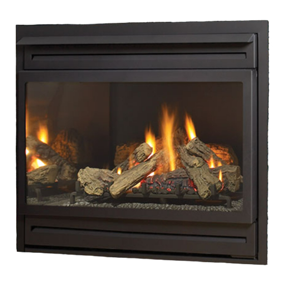
PG36 Gas Log Fireplace
Models: PG36NG-6
What to do if you smell gas:
Do not try to light any
appliance
Do not touch any electrical
switch: do not use any phone
in your building.
Immediately call your gas
supplier from a neighbour's
phone . Follow the gas
supplier's instructions.
If you
gas supplier, call the fire
department.
PG36LP-6
FOR YOUR SAFETY:
cannot reach your
01.09.20
Advertisement
Table of Contents

Subscribe to Our Youtube Channel
Related Manuals for Regency Fireplace Products Panorama PG36 Series


Summary of Contents for Regency Fireplace Products Panorama PG36 Series
- Page 1 Owners & Installation Panorama PG36 Gas Log Fireplace ® Models: PG36NG-6 PG36LP-6 PLEASE KEEP THESE INSTRUCTIONS FOR FUTURE REFERENCE WARNING: FOR YOUR SAFETY: Improper installation, adjustment, alteration, What to do if you smell gas: service or maintenance can cause injury or Do not try to light any property damage.
-
Page 2: To The New Owner
TO THE NEW OWNER: Congratulations! You are the owner of a state-of-the-art Gas Log Fireplace by FPI FIREPLACE PRODUCTS INTERNATIONAL LTD. The PG36 has been designed to provide you with all the warmth and charm of a wood fireplace at the flick of a switch. The model PG36 has been approved by the Australian Gas Association for both safety and efficiency. -
Page 3: Unit Dimensions
dimensions Unit Dimensions Regency PG36 Gas Fireplace ®... -
Page 4: Table Of Contents
table of contents Unit Dimensions ............3 Premium Flush Front Installation .........27 Wiring Diagram ............28 Safety Remote Control ............29 Data Badge ..............5 Operating Instructions ..........29 Lighting Instructions ............29 Installation Resetting the Unit ............29 Important Message ............6 Shutdown Instructions ..........29 Before You Start .............6 First Fire ..............29 General Safety Information ..........6 Operating Instructions... -
Page 5: Data Badge
data badge DATA BADGE NOTE: Regency This is a copy of the label that accompanies The label is located on the front inside base of units are ® each PG36 Zero Clearance Room Sealed Gas the unit, visible when the bottom louvre is open. constantly being improved. -
Page 6: Installation
installation Important Message Installation Checklist CLOTHING OR OTHER FLAMMABLE SAVE THESE INSTRUCTIONS MATERIAL SHOULD NOT BE PLACED 1. Locate appliance. Refer to the following sections: ON OR NEAR THE APPLIANCE. DO NOT The PG36NG-6 or PG36LP-6 Room Sealed USE AEROSOLS IN THE VICINITY OF THIS Fireplace must be installed in accordance with AS/ APPLIANCE. -
Page 7: Locating Your Fireplace
installation Locating Your Fireplace NOTE: The minimum floor clearance must 5. The PG36 Co Axial Flue Gas Fireplace is approved for alcove installations, which meet be maintained from the top surface of the the clearances listed on this page. 1. When selecting a location for your fireplace, carpeting, tile, etc. -
Page 8: Combustible Mantels
installation Note: A non-combustible mantel may be installed at a lower height if the framing is made of metal studs covered with a non-combustible board. Mantel Clearances with Flush Louvres - Black Premium Flush Front Plasterboard Non Combustible (see page 9) Regency PG36 Gas Fireplace ®... -
Page 9: Mantel Leg Clearances
installation Mantel Leg Clearances 3. Use steel studs for framing where the Top Header 38mm clearance from the flue to combustible material cannot be maintained, e.g. front top Combustible mantel leg clearances as per diagram 254mm dia. hole header. below: 13mm through wall for Flex Plasterboard... -
Page 10: Unit Assembly Prior To Installation
installation Unit Assembly Prior to Premium Flush Front Spacer Installation Installation Before the unit is slid into position, install the The Top Facing Support, the Side Nailing Strips and provided spacers to the side of the fireplace the 2 Top Standoffs must be correctly positioned and attached to the top before unit is slipped into as follows;... -
Page 11: Exterior Flue Termination Locations
installation Exterior Flue Termination Locations Minimum clearances required for balanced flue terminals or the flue terminals of outdoor appliances according to AS5601-2004 (AGA gas installation code) or NZS 5261 (New Zealand) Minimum Clearance (mm) Below eaves, balconies or other projections: - Appliances up to 50 MJ/h input - Appliances over 50 MJ/h input From the ground or above a balcony... -
Page 12: Flueing
installation Flueing Regency Direct Vent System (Flex) ® Horizontal Terminations Only These flueing systems, in combination with the PG36 Room Sealed Gas Fireplace, have been tested and listed as a Direct Vent type flue system by the Australian Gas Association. The location of the termination cap must conform to the requirements in the Flue Terminal Locations diagram in the "Exterior Flue Termination Locations"... -
Page 13: Horizontal Or Vertical Terminations
installation Horizontal or Vertical Terminations Simpson Dura-vent Flueing The Simpson Dura-Vent Co Axial Flue System offers a complete line of component parts for installation of both horizontal and vertical installations. Many items are offered in decorative black, as well as galvanized finish. We recommend using the galvanized finish for installation with the PG36. Wall thickness is measured from the back standoffs If a Vinyl Siding Standoff is required (it must be The minimum components required for a basic... -
Page 14: Flueing Arrangements - Horizontal Terminations
installation Flueing Arrangements - Horizontal Terminations SIMPSON DURA-VENT DIRECT FLUE GS SYSTEM and REGENCY® DIRECT FLUE SYSTEM (FLEX) (Propane & NG) Horizontal (Feet) The diagram shows all allowable combinations of vertical runs with horizontal terminations, using one 90 elbow (two 45 elbows equal one 90 elbow). - Page 15 installation Flueing Arrangements - Horizontal Terminations SIMPSON DURA-VENT DIRECT FLUE GS SYSTEM and REGENCY® CO AXIAL FLUE SYSTEM (FLEX) (Propane & NG) The diagram below shows examples of horizontal termination arrangements using two 90 elbows (two 45 elbows equal one 90 elbow).
-
Page 16: Flueing Arrangements - Vertical Terminations
installation Flueing Arrangements - Vertical Terminations SIMPSON DURA-VENT CO AXIAL FLUE GS SYSTEM (Propane & NG) The PG36 is approved for a 7.0m vertical, with a maximum 3.7m horizontal offset using two 90 elbows elbow) with Simpson Dura-Vent Co Axial Flue GS flue systems for (two 45 elbows equal one 90 Propane and NG, as per diagram 1. -
Page 17: Vent Restrictor Installation
installation The PG36 is approved for a 37 ft. (11.3 m) straight vertical, with Simpson Dura- Vent Co Axial Flue GS flue systems for Propane and NG, as per diagram 3. The shaded area in diagram 3 shows all allowable combinations of straight vertical and offset to vertical terminations with Simpson Dura-Vent Co Axial Flue GS flue systems for Propane and NG. -
Page 18: Direct Flue Zero Clearance Top Exit Vertical Flue Kit Installation Instructions
installation Direct Flue Zero Clearance Top Exit Vertical Flue Kit Installation Instructions This flue kit has been manufactured for use with PG36 and to be installed in accordance with AS/NZS 5601. To ensure safety and correct unit operation this flue kit must be installed as outlined in these instructions. Heater and flue clearances from combustible materials must be in accordance with these instructions and AS/NZS 5601. -
Page 19: Horizontal Terminations
installation Horizontal Terminations Note: Apply sealant "Mill-Pac" to inner pipe and high temperature silicone Install the flue system according to the sealant to outer pipe on every twist- manufacturer's instructions included with the lock joint. components. b) Horizontal runs of flue must be supported 1) Set the unit in its desired location. -
Page 20: Vertical Terminations
installation Vertical Terminations 4. Assemble the desired lengths of pipe and Galvanized pipe is desirable above the roofline elbows. Ensure that all pipes and elbow due to its higher corrosion resistance. Continue connections are in the fully twist-locked position to add pipe sections through the flashing until 1) Maintain the 32mm clearances (air spaces) and sealed. -
Page 21: Gas Connection
installation Aeration Adjustment 1. Make sure the valve is in the "OFF" position. PG36NG-6 System Data 2. Loosen the "IN" (# 3) and/or "OUT" (# 4) The air shutter can be adjusted by moving the pressure tap(s), turning counterclockwise with For 0 to 4500 feet altitude adjusting wire up or down. -
Page 22: Conversion From Ng To Propane Kit
PG36NG-6/PG36LP-6 installation Conversion Kit #517-968 from NG to LPG Conversion From NG To Propane Kit #517-968 THIS CONVERSION MUST BE DONE BY A QUALIFIED GAS FITTER, IF IN DOUBT DO NOT DO THIS CONVERSION !! THIS CONVERSION MUST BE DONE BY A QUALIFIED GAS FITTER IF IN DOUBT DO NOT DO THIS CONVERSION!! Adjust the burner aeration setting to full Propane Conversion Kit Contains: open and re-install the burner. - Page 23 PG36NG-6/PG36LP-6 installation 15) Remove the heat shield from the ECS 18) Stick the conversion label "This unit has WARNING: To ensure the correct operation of been converted to LPG" on the control the modulator it is necessary that box by undoing the 2 screws. box cover. the plastic cap (A) is returned to its original location. 19) Reverse steps 15 and 14. 20) Turn on gas supply and plug in power cord. 21) Adjusting the Outlet Pressure: All the adjustments must be carried out in the following order: Remove the modulator plastic cap (A) using needle nose pliers. Heat Shield ECS Box Maximum pressure: Turn the unit ON to its highest input rating. Screw in the nut (B) to increase the outlet pressure 16) Remove the control box cover by and screw it out to decrease it. Use a 10 undoing the 3 screws. Maneuver through mm wrench.
-
Page 24: Log Set Installation
installation Log Set Installation Read the instructions below carefully and 02-49 refer to the diagrams. If logs are broken do 02-49 not use the unit until they are replaced. Broken logs can interfere with the pilot operation. 02-53 02-51 The gas log kit (Part # 512-930) contains the following pieces: a) 02-49 Rear Log... - Page 25 installation 8) Position Log 02-54 across the cutouts in Logs 10) Place the embers on the front of the burner tray 02-51 and 02-53. The notch in the bottom in the places shown on the photo. right end fitting against the 5th grate tab. 02-54 02-51 Place embers in these 3 locations...
-
Page 26: Standard Flush Door
installation Standard Flush Door The standard flush door comes with a black frame. To install the frame, hook the top door flange onto Use the hook to pull the spring out until you can put the top of the unit and swing the door towards the the hook into the slot on the bottom door bracket. -
Page 27: Premium Flush Front Installation
PG36 / PG36D installation PREMIUM FLUSH FRONT INSTALLATION Premium Flush Front Installation 1) Unplug the power source. 6) Remove the bottom louver (if fi tted) by undoing the 2 screws which secure the louver to the hinges on the left and right side. 2) Remove the top louver (if fi... -
Page 28: Wiring Diagram
installation Wiring Diagram Regency PG36 Gas Fireplace ®... -
Page 29: Remote Control
operating instructions Remote Control Lighting Instructions First Fire Use the Regency Remote Control Kit approved 1. Plug the power cord into a power outlet. ® The FIRST FIRE in your heater is part of the for this unit. Use of other systems may void your paint curing process. -
Page 30: Operating Instructions
operating instructions Adjusting Flame Height Pilot Adjustment Normal Operating Sounds of Gas Appliances Periodically check the pilot flames. Correct flame There are six flame settings that can be adjusted pattern has two strong blue flames: 1 flowing around It is possible that you will hear some sounds from by pressing and releasing the plus (+) and minus the flame sensor and 1 flowing across the burner (it your gas appliance. -
Page 31: Copy Of The Lighting Plate Instructions
operating instructions Copy of the Lighting Plate Instructions AS/NZS 5601. SUITABLE ONLY FOR INDOOR INSTALLATION 918-332C WARNING: DO NOT SPRAY AEROSOLS IN THE VICINITY OF THIS APPLIANCE WHILE IN OPERATION. Part #: 918-332c (for ECS units, except for FG38) Regency PG36 Gas Fireplace ®... -
Page 32: Maintenance
maintenance Maintenance Instructions General Flue Maintenance WA R N I N G : C H I L D R E N A N D ADULTS SHOULD BE ALERTED Conduct an inspection of the flueing system semi- Any maintenance required accessing the TO THE HAZARDS OF HIGH annually. -
Page 33: Log Replacement
maintenance Log Replacement Regency dealer only, and follow our step-by- ® step instructions for replacement. The unit should never be used with broken logs. Turn off the gas valve and allow the unit to cool before opening door and carefully remove the logs. If for WARNING: Do not operate the appliance any reason a log should need replacement, you with the glass panels removed,... -
Page 34: Removing Valve Tray
maintenance Removing Valve Tray 1. Shut off the gas supply. 2. Remove the louvres. 3. Open the flush door and remove door. 4. Remove the logs. 5. Remove the burner/grate assembly by removing the left and right side Phillips head screws and then lift the burner assembly out. 9. -
Page 35: Fan Replacement
maintenance Fan Replacement 1. Shut off the power supply. 7. Unplug the black wire from the resister. 2. Remove the top louvre. 8. Carefully slide the fan to the front left side of the unit. 3. Remove the glass door. 9. -
Page 36: Manual Control Switch Replacement
maintenance Manual Control Switch Replacement 1. Unplug the power source. 7. Remove the heat shield from the ECS box by undoing the 2 screws. 2. Open the bottom louver. 3. Remove the 3 screws that secure the manual control louver bracket to the louver. -
Page 37: Electronic Components Parts List
parts list Electronic Components Parts List Note: Depending on the model, the diagram below may not be exactly as shown - for reference purposes only. 910-936 910-082 910-089 910-088 910-912 910-084 911-101 910-080 911-183 910-514 910-521, 910-522, 910-523 910-083 910-527 / 910-935 910-922 FG38 FG39... -
Page 38: Main Assembly
parts list Main Assembly Part # Description 948-045 Chain 948-025 Spring 910-169/P Fan Motor 910-904 Wire Harness (Fan End) 910-714 Power Cord (240 V) 14) 510-026 Hinge Bracket - Left/Right 15) 948-253 Door Handle 17) * Wire Holder Clip 20) 510-033 Top Nailing Strip 21) 510-064 Side Nailing Strip... -
Page 39: Burner Assembly & Log Set
parts list Burner Assembly & Log Set Part # Description 516-574/P Valve Assy - NG 516-576/P Valve Assy - LPG 910-080 Sigman Gas Valve 53) 430-055 Gasket - Valve Access Plate NS 910-936 Pilot Assembly 904-240 Orifice #37 - NG (Burner) 904-390 Orifice #52 - LPG (Burner) 910-036... -
Page 40: Flush Front Accessories
parts list Flush Front Accessories Part # Description 132) 512-518 Flush Door Assembly 135) 940-090/P Glass (Flush) 136) 936-155 Glass Gasket (Tadpole) 904-691 U-Clip 138) 510-922 Flush Louvres-Black (set) 904-196 Magnet (1" round) 510-934 Flush Glass Trim - Brass (2/Set) 510-947 Flush Glass Trim - Steel (2/set) 510-986... -
Page 41: Premium Flush Front Assembly
parts list Premium Flush Front Assembly Part # Description 516-916 Premium Flush Front - Black 516-948 Wiring 910-975 Thermodisc 180) * Top Louver 181) * Bottom Louver 182) * Thermodisc Mounting Bracket 183) * Spacers *Not available as a replacement part. Regency PG36 Gas Fireplace ®... -
Page 42: Warranty
warranty Limited Lifetime Warranty FPI Fireplace Products International Ltd. (“the manufacturer”) through its wholly owned subsidiary, Fireplace Products Australia Pty Ltd (for Australia and New Zealand customers) and sold under the Regency® brand of fireplace products (collectively referred to herein as “FPI”), extends this Limited Lifetime Warranty to the original purchaser of this appliance provided the product remains in the original place of installation. - Page 43 warranty part is returned to the distributor, dealer or agent for inspection if requested by FPI. Alternatively, FPI may at its own discretion fully discharge all of its obligations under the warranty by refunding the verified purchase price of the product to the original purchaser. The purchase price must be confirmed by an original copy of the tax invoice. The authorised selling dealer, or an alternative authorised FPI dealer if pre-approved by FPI, is responsible for all in-field diagnosis and service work related to all warranty claims.
- Page 44 warranty FPI has no obligation to enhance or modify any unit once manufactured (i.e. as products evolve, field modifications or upgrades will not be performed on existing appliances). Any unit showing signs of neglect or misuse will not be covered under the terms of this warranty policy and may void this warranty.
- Page 45 warranty Limitations of Liability: 1. Exclusion of implied terms The customer may have the benefit of consumer guarantees under the Australian Consumer Law. To the maximum extent permitted by law, all terms, conditions or warranties that would be implied into this Warranty or in connection with the supply of any goods or services by the supplier under law or statute or custom or international conventions are excluded.
- Page 46 warranty How to Obtain Warranty Service: Customers should contact the authorised selling dealer to obtain warranty service. In the event the authorised selling dealer is unable to provide warranty service, please contact FPI by mail at the address listed below. Please include your name, address, purchase date, selling dealer, serial #, type of unit, a brief description of the problem, email and telephone contact information, and a copy of your original tax invoice.
- Page 47 Regency PG36 Gas Fireplace ®...
- Page 48 Installer: Please complete the following information Dealer Name & Address: ______________________________________________ ___________________________________________________________________ Installer: ___________________________________________________________ Phone #: ___________________________________________________________ Date Installed: ______________________________________________________ Serial No.: __________________________________________________________ Printed in Canada © Copyright 2020, FPI Fireplace Products International Ltd. All rights reserved.
Need help?
Do you have a question about the Panorama PG36 Series and is the answer not in the manual?
Questions and answers