Samsung iDCS 500 General Description Manual
Digital communications system
Hide thumbs
Also See for iDCS 500:
- Programming manual (533 pages) ,
- User instruction (140 pages) ,
- Technical manual (137 pages)
Table of Contents
Advertisement
Quick Links
Digital Communications System
General Description
Every effort has been made to eliminate errors and ambiguities in the information
contained in this guide. Any questions concerning information presented here
should be directed to SAMSUNG TELECOMMUNICATIONS AMERICA, 2700 NW
87th Avenue, Miami, FL 33172, telephone (305) 592-2900. SAMSUNG
TELECOMMUNICATIONS AMERICA disclaims all liabilities for damages arising
from the erroneous interpretation or use of information presented in this guide.
Advertisement
Table of Contents

Related Manuals for Samsung iDCS 500


Summary of Contents for Samsung iDCS 500
-
Page 1: General Description
Every effort has been made to eliminate errors and ambiguities in the information contained in this guide. Any questions concerning information presented here should be directed to SAMSUNG TELECOMMUNICATIONS AMERICA, 2700 NW 87th Avenue, Miami, FL 33172, telephone (305) 592-2900. SAMSUNG TELECOMMUNICATIONS AMERICA disclaims all liabilities for damages arising from the erroneous interpretation or use of information presented in this guide. - Page 2 Publication Information SAMSUNG TELECOMMUNICATIONS AMERICA reserves the right without prior notice to revise information in this publication for any reason. SAMSUNG TELECOMMUNICATIONS AMERICA also reserves the right without prior notice to make changes in design or components of equipment as engineering and manufacturing may warrant.
-
Page 3: Table Of Contents
T A B L E O F C O N T E N T S PART DESCRIPTION PAGE SYSTEM OVERVIEW GENERAL DESCRIPTION ................... 1.2 SIZE AND CONFIGURATION ................1.2 TECHNOLOGY ....................1.5 PROGRAMMING ....................1.5 HARDWARE DESCRIPTIONS SYSTEM CABINETS ................... 2.1 COMMON CONTROL CARDS ................ - Page 4 6.3.3 TRANSACTION RECORD OUTPUT SAMPLE ........6.25 6.3.4 INDIVIDUAL GUEST PHONE BILL ............6.27 6.3.5 ALL GUEST PHONE BILL (SMDR) ............6.29 6.3.6 INDIVIDUAL WAKEUP ACTIVITY REPORT ........... 6.30 6.3.7 SAMSUNG SINGLE LINE TELEPHONE SAMPLE GUEST PHONE TEMPLATE ..........6.32...
- Page 5 500 GENERAL SYSTEM DIAGRAM...
-
Page 6: System Overview
PABX or a combination of both (hybrid). The DCS employs DSP (Digi- tal Signal Processors) digital technology. The iDCS 500 offers a variety of interface cards that allow connection to the public tele- phone network or to private networks. These are generally referred to as trunk cards. Two types of telephones can be connected to the system. - Page 7 SINGLE CABINET SYSTEM A single cabinet system has nine universal card slots, a processor slot and two power supply slots, the first of which must be occupied by a PSU-B (see Figure 1–1). Station or trunk (line) cards can be installed in any of the nine universal slots.
- Page 8 Local Control Processor (LCP) in a similar manner to the SCP in the first cabinet and con- nects to the MCP via a 25 pair cable. The LCP processor card resides in a dedicated slot 10 of the second cabinet and therefore does not deplete the number of universal card slots.
-
Page 9: Technology
LAN interface module (LAN). MICROPROCESSORS The iDCS 500 uses distributed processing. Its primary processor is a 16 bit (32 bit core) Motorola MC68302 operating at a clock speed of 25 MHz on the MCP card. This provides all the processing necessary for a single cabinet system. - Page 10 The iDCS 500 also allows the use of a proprietary computer program called SAPM-PCMMC. This permits a technician to program the system using a personal computer. SAPM- PCMMC can be used on-site to modify the customer database or to download (save) the entire customer database to a file.
-
Page 11: Hardware Descriptions
2.2 COMMON CONTROL CARDS 2.2.1 PROCESSOR CARDS The iDCS 500 requires a processor card or cards in order to operate. In a single cabinet iDCS 500 system, only one processor card, the Main Control Processor (MCP), is required. When the system is expanded to two or three cabinets a second, Signal Control Proces- sor (SCP), is required for the main cabinet to assist the MCP and each expansion cabinet requires its own Local Control Processor (LCP). - Page 12 the RCM or the Local Area Network (LAN) board in a single cabinet system. This position is also required to support the Inter Processor communications and Memory (IPM) daugh- ter board in a multiple cabinet system or a system running the L version software. The third daughter board (MCP_D3) can support a Miscellaneous (MISC) daughter board or a Local Area Network (LAN) daughter board in a single cabinet system or a LAN daughter board in a multiple cabinet system.
-
Page 13: Processor Card Daughter Boards
LOCAL CONTROL PROCESSOR (LCP) The Local Control Processor (LCP) card is installed in a dedicated processor slot, slot 10, of each Expansion KSU and does not reduce the available universal card slots of that cabinet. The LCP card has positions for three daughter boards. The first daughter board position (SCP-D1) can support one of two types of daughter board, a Multi-Frequency Module (MFM), or an R2/CID Module (RCM). - Page 14 LOCAL AREA NETWORK (LAN) This daughter board installs in either position MCP-D2 or MCP-D3 of the Main Control Processor and provides a 10/100 base T Ethernet LAN connection. In addition to the LAN connection, the LAN board provides 0.5 megabytes of SRAM to support the increased I/O functions of this card.
-
Page 15: Smartmedia Cards
Two (2) software assignable relay contact closures 2.2.3 SMARTMEDIA CARDS An iDCS 500 system must have a SmartMedia card installed in the main control processor (MCP) as the SmartMedia card contains the system operating software. The SmartMedia card can also be used to store a backup customer database to supplement the database stored on the MCP card. -
Page 16: Modem Daughter Board
These cards provide the interface connections for telephone lines and stations to the KSU and expansion cabinets. These cards fit into the universal card slots to configure the sys- tem as required. iDCS 500 interface cards are encased in a static dissipative ABS plastic shell to protect the PCB during handling. - Page 17 TEPRI DIGITAL TRUNK When programmed as a T1 this card provides up to 24 trunk circuits in any combination of the following: Loop start lines DID (Direct Inward Dialing) Ground start lines E & M tie lines or two way DID calling When the card is programmed as a PRI it will provide 23 bearer channels and 1 data channel (23B+D).
-
Page 18: Station Cards
2.3.2 STATION CARDS This card is an eight circuit digital station interface card that provides 2B+D service when installed in any universal card slot in all cabinets. 16DLI This card is a sixteen circuit digital station interface card that provides 1B+D service when installed in any universal card slot in all cabinets. - Page 19 at a programmable rate of 100ms to 2000ms ON/OFF times. The 8MWSLI does not con- tain any over-voltage protection and is not qualified as OPX. It also does not contain DTMF receivers, but instead shares the system DSP resources. It can be inserted in any univer- sal card slot in all cabinets.
-
Page 20: Other Cards
2.3.3 OTHER CARDS AUTO ATTENDANT This optional card can be used for either the Automated Attendant, Uniform Call Distribu- tion or a combination of both. For more information about the Automated Attendant and UCD, see section 4.1 System Features. CADENCE (CVM8A) The CADENCE Voice Mail system is a fully integrated Auto Attendant/Voice Mail/Fax Sys- tem on a single DCS circuit card. -
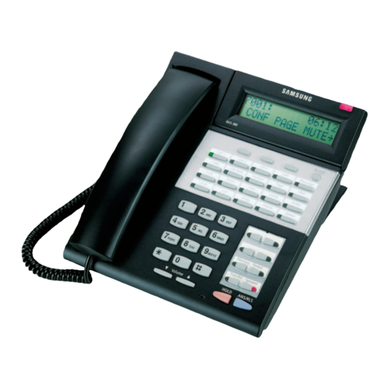
Page 21: Station Equipment
2.4 STATION EQUIPMENT 2.4.1 iDCS SERIES EQUIPMENT iDCS 28D KEYSET (See Figure 2–1) 32 character display (2 x 16) with three associated soft keys and a scroll key 28 programmable keys with tri-colored lights Four fixed function keys Terminal Status Indicator Built-in speakerphone Eight selectable ring tones UP/DOWN buttons for digital control of... - Page 22 iDCS 8D KEYSET (see Figure 2–3) 32 character display (2 x 16) with three asso- ciated soft keys and a scroll key 8 programmable keys with tri-colored lights Four fixed function keys Terminal Status Indicator Built-in speakerphone Eight selectable ring tones UP/DOWN buttons for digital control of speaker, handset and ringer volumes Desk- or wall-mounted...
- Page 23 iDCS KDB-DIGITAL LINE INTERFACE (FKDBD) This is a daughterboard that can be installed only in the 18 or 28 button keyset. The FKDBD will provide one additional DLI circuit for the connection of any digital station de- vice such as a keyset, add-on module or DPIM. This FKDBD will only operate when the keyset is connected to an 8 port DLI card so it can use the second B channel.
-
Page 24: Dcs Series Equipment
2.4.2 DCS SERIES EQUIPMENT LCD 24B KEYSET (See Figure 2–6) Built-in speakerphone 24 programmable keys (16 with tri-col- ored LEDs) Four fixed function keys 32 character display (2 x 16) with three associated soft keys and a scroll key UP/DOWN buttons for digital control of speaker, handset and ringer volumes Eight selectable ring tones Desk- or wall-mounted... - Page 25 32 BUTTON ADD-ON MODULE (AOM) (see Figure 2–9) 32 programmable keys Two fixed function keys UP/DOWN buttons for digital control of speaker and ringer volumes Available in almond or charcoal One or two can be assigned to any DCS keyset to provide executive off-hook voice announce and additional programmable keys (see Figure 2–10) Can operate as a stand-alone handsfree tele-...
-
Page 26: Single Line Telephone
FIGURE 2–12 64 BUTTON MODULE (See Figure 2–13) 64 programmable keys Available in almond and charcoal A maximum of 2 can be assigned to any DCS keyset to provide additional programmable keys A maximum of 4 per DCS System FIGURE 2–13 SINGLE LINE TELEPHONE (See Figure 2–14) Four fixed function keys: hold, flash, new... - Page 27 KDb-DLI This is a daughterboard that can be installed only in the 12 or 24 button keyset. The KDb- DLI will provide one additional DLI circuit for the connection of any digital station device such as a keyset, add-on module or DPIM. This KDb-DLI will only operate when the keyset is connected to an 8 port DLI card so it can use the second B channel.
-
Page 29: Specifications
PART 3. SPECIFICATIONS The following tables provide technical data for the iDCS 500 hybrid/key telephone sys- tem. 3.1a ELECTRICAL SPECIFICATIONS (PSU 60) AC INPUT 120 (88–132) VAC (48–63 Hz)* 220 (180–260) VAC (48–63 Hz) POWER CONSUMPTION (MAX) 120 WATTS MAX. PER PSU FUSE RATING 3 AMP BTU RATING (MAX) 6.8 BTU/MINUTE... -
Page 30: Dimensions And Weights
DIMENSIONS AND WEIGHTS HEIGHT WIDTH DEPTH WEIGHT iDCS 500 BASIC SYSTEM: SINGLE CABINET 17.5" 22.5" 12" 35 lb. EXPANDED SYSTEM: TWO CABINETS 35" 22.5" 12" 70 lb. EXPANDED SYSTEM: THREE CABINETS 52.5" 22.5" 12" 105 lb. DIGITAL KEYSET (ALL MODELS) 4.25"... -
Page 31: System Tones
SYSTEM TONES TONE FREQUENCIES CADENCE DIAL TONE 350 + 440 Hz CONTINUOUS RINGBACK TONE 440 + 480 Hz 1 sec on + 3 sec off DID RINGBACK TONE 440 + 480 Hz 2 sec on + 4 sec off BUSY TONE 480 + 620 Hz 0.5 sec on + 0.5 sec off DND/NO MORE CALLS... -
Page 32: Keyset Led Indications
Transfer/Conference Tone—Indicates your call is being held and you can dial another party. TRANSFER/CONF TONE—100 ms ON/100 ms OFF CONTINUOUS Confirmation Tone—Very short beeps followed by dial tone indicate you have correctly set or canceled a system feature. CONFIRMATION TONE—50 ms ON/50 ms OFF FOR TWO SECONDS ERROR TONE—A distinctive two level beeping tone indicates you have done something incorrectly. -
Page 33: Reserve Power Duration Estimates (Ups)
3.7a RESERVE POWER DURATION ESTIMATES (in minutes)* UPS CAPACITY IN VOLT AMPS (VA) NO. OF PSUs 1250 2000 *These are approximate values. Specific UPS devices, due to their internal construction, can have greater or lesser values. 3.7b RESERVE POWER DURATION ESTIMATES (in minutes)* BATTERY CAPACITY IN AH NO. -
Page 35: Business Feature Package
PART 4. BUSINESS FEATURE PACKAGE SYSTEM FEATURES Account Code Entry Common Bell Control Override Code Forced - Verified Conference Paging Forced - Not Verified Add On (5 Party) Internal Zones (4) Unsupervised Voluntary External Zones (4) Split (L Version) Account Code Key (M Version) All Internal Account Code Key - One Touch (L Version) Computer Telephony Integration (CTI) -
Page 36: System Features Descriptions
4.1 SYSTEM FEATURE DESCRIPTIONS ACCOUNT CODE ENTRY Station users may enter an account code (maximum 12 digits) before hanging up from a call. This account code will appear in the SMDR printout for that call record. Keyset users may enter this code using an account code key without interrupting a conversation. - Page 37 When a station is programmed for forced authorization, the user must always enter this code before dialing is allowed. The dialed authorization code is verified from the system list of 250 authorization codes on a iDCS 500-M system or 500 on a iDCS 500-L system.
-
Page 38: Automatic Hold
Mailbox Administration with interactive keyset displays. Ask your dealer for litera- ture on Cadence. CALL ACTIVITY DISPLAY The iDCS 500 will record and buffer all calling activity within the system. With a Call Activity Display (CAD) key, the iDCS 500 will display a “snapshot” of the following information: •... - Page 39 CALL COSTING The iDCS 500 provides programmable call costing tables to calculate the cost of incoming and outgoing calls. Rates are calculated by the number dialed, and may include surcharges. Display keysets can be set to show the call duration timer or the call cost.
-
Page 40: Caller Id Features
CALLER ID FEATURES The following features apply to all forms of Caller Identification, however, to make them easier to read caller identification is referred to as Caller ID. NAME/NUMBER DISPLAY Each LCD keyset user can decide if he/she wants to see the name or number in the display. -
Page 41: Abandon Call List
Caller ID name, number and the date and time the call came in. The system must be using LCR to dial numbers from the abandon call list. The abandoned call list will store up to 50 unanswered calls on iDCS 500-M version software and 100 unanswered calls on iDCS 500-L version software. -
Page 42: Forward Dnd
key is programmed as Forward All, the TRSF key lights steady when a Forward All condition is set. BUSY This feature forwards all calls only when the station set is busy. The station user can originate calls as usual. NO ANSWER This feature forwards calls that are not answered within a preprogrammed time. -
Page 43: Call Park And Page
feature is the same as the normal forward busy where when the forwarded station is busy a calling station will be forwarded to the forward destination. CALL FORWARD NO RESPONSE (CFNR) (LE VERSION) This is a different feature from the normal call forward no answer and is only used when the forward destination is in a different node of the network. - Page 44 This service is sometimes referred to as Enhanced 911 or E-911. This service is provided in two forms in the iDCS 500, either via a dedi- cated 4 port Centralized Automatic Message Accounting (CAMA) trunk card called the E911 card or via an ISDN PRI circuit configured for both way DID connected to the TEPRI card.
-
Page 45: Chain Dialing
(trunk to trunk) conference. SPLIT (iDCS 500-L version software only) A keyset user can “split” a conference into separate outside calls, then speak with each caller privately. Then the individual calls can be conferenced again in any combination. -
Page 46: Customer Set Relocation
L version system. TAPI 2.1 TAPI 2.1 is the method of integrating the iDCS 500 system to a computer. TAPI 2.1 is a LAN based solution allowing computers to communicate directly to the telephone system over the network system. This establishes a logical connection rather than a physical connection between telephone and computer. - Page 47 Direct Dial In (DDI). This is the name given to the above three services when they are provided over an ISDN PRI circuit. The L version of the iDCS 500 has an option to select which MOH source is played to callers to a specific DID number.
-
Page 48: Directory Names
Dial by Name feature (Station Features). DISA SECURITY Telephone fraud and long distance theft are a serious concern. The iDCS 500 pro- vides a strong DISA security system. If an incorrect DISA passcode is entered re- peatedly (as is the case with “hackers”), the DISA system can be automatically disabled temporarily. - Page 49 This feature allows the user who barged-in to retain the trunk call after the original station has hung up. WARNING: BARGE-IN WITHOUT TONE MAY VIOLATE STATE OR FEDERAL LAWS CONCERNING THE RIGHT TO PRIVACY. SAMSUNG TELECOMMUNICATIONS AMERICA IS IN NO WAY RESPONSIBLE FOR THE POSSIBLE MISUSE OF THIS FEATURE.
- Page 50 The iDCS 500 MISC card provides two inputs for connecting to customer provided external music sources. Each cabinet of the iDCS 500 can support one MISC card for a total of three cards or six sources in a maximum sized system. These sources can be used to provide background music, or any of the varied Music On Hold (MOH) uses.
- Page 51 (the “D” of 23B+D) thus leaving the bearer channels (the “B” of 23B+D) available for single use or combined use to provide a wider bandwidth for data and video. The iDCS 500 supports the most popular protocol standards in the U.S.
- Page 52 LEAST COST ROUTING Least Cost Routing (LCR) is the ability to automatically select the most cost effec- tive central office route for the outside number dialed by any station. The iDCS 500 LCR program includes the following features: Option to use or not use LCR or a tenant basis...
-
Page 53: Message Waiting Key
MUSIC ON HOLD—FLEXIBLE The iDCS 500 allows its music sources to be used in a very flexible manner as follows: Each keyset can have a designated music source for playing as Background Mu- sic (BGM) through the keyset speaker. - Page 54 Voicemail Sound File: If the iDCS 500 system has an optional CADENCE card in- stalled, up to 100 custom recorded sound files from the Voice Mail card can be used for MOH sources. For information on creating the sound files see CADENCE System Administrator Manual-Recording greeting by number.
- Page 55 Forward External. This feature operates in the same manner as a non networked system with the exception that, because calls across a network link are trunk calls, network calls do not follow the ICM FWD EXT ON/OFF setting in MMC 210. It is therefore suggested that this setting be set to ON in a networked switch to avoid confusion in operation between networked and non networked calls.
-
Page 56: Operator Group
The basis of this feature is an override code table containing 5 entries of up to 11 digits each. The iDCS 500 will examine digits that are dialed from a station to see if they match any entry in the Override Code table. - Page 57 PARK ORBITS The system has 10 park orbits (0–9). These orbits can be used to park calls prior to paging and allows the call to be retrieved by dialing a park code plus the orbit number. Calls parked in this manner can also be retrieved by dialing the park pickup code (10) plus the station or trunk number.
-
Page 58: Holiday Schedule
Auto Answer intercom call being made to the executive (providing the executive is free). The iDCS 500 L version software has a system wide option to allow the stations to ring rather than auto announce the executive secretary calls. - Page 59 24 digits. SPEED DIAL BY DIRECTORY The iDCS 500 system provides the user with the ability to look up a speed dial number and place the call. There are three speed dial selections: personal, sys- tem and station.
- Page 60 TENANT SERVICE (2) The iDCS 500 supports two forms of tenant service as detailed below. SYSTEM SPLITTING: In the first form there are several programs that allow the idcs 500 to be installed in tenant applications. These features allow a technician to split...
-
Page 61: Toll Restriction Override
TRAFFIC REPORTING The iDCS 500 system can store peg counts for various types of calls. These peg counts can be printed on-demand, daily, hourly, or up to three separate program- mable shifts. The report includes statistics for each trunk, trunk group, station, sta- tion groups and page announcements. - Page 62 VIRTUAL SINGLE LINE TELEPHONE The idcs 500 has a number of virtual SLT ports encoded in the system database. The M version has 14 and the L version has 70. These ports have all the attributes of an actual SLT port including call forwarding.
- Page 63 They may need to be changed if you are using another system. VoIP The iDCS 500 ITM3 VoIP card supports up to eight voice calls over an IP network connection using the industry standards based H.323 protocol. An additional eight VoIP channels can be added by installing an eight-circuit daughterboard for a total of sixteen channels of VoIP .
-
Page 64: Walking Class Of Service
WALKING CLASS OF SERVICE This feature allows users to make calls or use features from a station that is re- stricted. The users may either use the WCOS feature code or the authorization code feature. Both methods change the class of service to correspond with the station passcode or authorization code that is dialed. -
Page 65: Station Features Descriptions
STATION FEATURES ADD-ON MODULE PRIVACY RELEASE (L Version) APPOINTMENT REMINDER PROGRAMMABLE KEYS AUTOMATIC HOLD PROGRAMMED STATION MESSAGES AUTOMATIC PRIVACY PROTECTION FROM BARGE-IN BACKGROUND MUSIC PULSE TO TONE SWITCH OVER BUSY STATION CALLBACK REDIAL BUSY STATION INDICATIONS (BLF) AUTO RETRY CALL FORWARDING LAST NUMBER CALL LOGS MEMO REDIAL... - Page 66 LED can be used for feature keys, DSS/BLF keys or one touch speed dial buttons. A maximum of 4 can be installed on a iDCS 500 system running iDCS 500- M version software, or a maximum of 32 can be installed on a iDCS 500 system running iDCS 500-L version software.
- Page 67 Pickup keys may be customized with extenders to allow pickup from a specific station or pickup group. The iDCS 500-M version software has 20 programmable pickup groups and the iDCS 500-L version software has 99 programmable pickup groups.
- Page 68 The ANS/RLS key lights if headset mode is activated by keyset programming only. HEARING AID COMPATIBLE All iDCS 500 keysets are hearing aid compatible as required by Part 68 of the FCC requirements. 4.34...
- Page 69 MANUAL SIGNALLING (iDCS 500-L version software only) Keysets can signal each other via a programmable key. This allows one station to alert another without establishing a voice conversation. Each press of the key re- sults in a 500 milliseconds of ring tone being set to the intended station.
-
Page 70: Programmable Keys
PRIVACY RELEASE (iDCS 500-L version software only) This feature will allow another station to join in on your conversation by temporarily releasing privacy on the C.O. line from your keyset. - Page 71 Any station may select one of 20 or 30 messages to be displayed at a calling party’s keyset (20 for iDCS 500-M version software and 30 for iDCS 500-L version software). Ten messages are factory-programmed but may be reprogrammed. On iDCS 500-L version software two can be individually customized, i.e., RETURN...
-
Page 72: Remote Hold
REMOTE HOLD When you wish to place a call on hold at another station, press TRSF and dial the station number (or press the appropriate DSS key). Press the HOLD key. This will place the call on system hold on an available CALL button or Line Key at the re- mote station. - Page 73 TERMINAL STATUS INDICATOR iDCS keysets are equipped with a terminal status indicator lamp. The terminal status indicator light is positioned on the top right corner of the keyset above the display. The terminal status indicator is a tri-colored (red, green, and amber) light that provides greater visibility of your keysets status than the individual key LEDs.
-
Page 74: Display Features Descriptions
DISPLAY FEATURES ACCOUNT CODE DISPLAY ENHANCED STATION PROGRAMMING CALL DURATION TIMER IDENTIFICATION OF RECALLS CALL FOR GROUP IDENTIFICATION IDENTIFICATION OF TRANSFERS CALL PROCESSING INFORMATION MESSAGE WAITING CALLER NUMBER CALLER ID INFORMATION OUTSIDE LINE IDENTIFICATION CALLING PARTY NAME OVERRIDE IDENTIFICATION CALLING PARTY NUMBER PROGRAMMED MESSAGE DISPLAY CONFERENCE INFORMATION SOFT KEYS... - Page 75 If CID/ANI information is available for an incoming call, the selected stations can know to whom the iDCS 500 user is speaking. On outgoing calls, the selected stations can see who was called. After investigating, the se- lected stations may barge-in on the conversation, disconnect the call or hang up.
-
Page 76: Calling Party Number
ANI number and the date and time the call came in. The system must be using LCR to dial numbers from the abandon call list. The abandoned call list will store up to 50 unanswered calls on iDCS 500-M version software and 100 unanswered calls on iDCS 500-L version software. - Page 77 Users simply press once to start the timer and press again to stop the timer. TEXT MESSAGING (iDCS 500-L version software only) This feature allows two display keyset users to respond to each other with preprogrammed messages. After receiving an Off Hook Voice Announcement or Station Camp-On, you may respond with a text message while continuing to talk and listen to your outside party.
-
Page 78: Call Screen
ming (MMC 318) will receive the TMSG soft key in the display and can use this feature. UCD SUPERVISOR DISPLAYS With the optional AA card, when UCD is used, multiple supervisors can view infor- mation about the UCD groups calls or agents. CALL SCREEN This allows the supervisor to view how many calls are in queue, the longest wait time, how many calls have been received today, what the average time in queue is... - Page 79 SAMPLE DISPLAYS Display model keysets have a large, easy-to-read, 32 character liquid crystal display. Helpful call processing information is provided so everyday call handling is quick and easy. Here are just some of the displays you may see. Camp on to 203 209:Tim Kelly Wait for answer FRI 23 Sep 02:54...
- Page 80 DROP This display shows an investigation of a This display is seen while examining calls in station that is talking to Samsung Telecom. queue at your keyset. Investigator can BARGE-in to the conversa- tion, DROP the call from the system or examine further NND information.
- Page 81 SAMPLE UCD DISPLAYS 005 calls in 06 available queue now 04 logged in There are five calls currently waiting to be There are six members in the group. Four answered by the UCD group. the members are currently logged in. 201: answered longest wait 065 calls today...
- Page 82 4.48...
- Page 83 4.49...
-
Page 84: Sample Ucd Report
4.6 SAMPLE UCD REPORT ======================================================= UCD GROUP 529 : SALES FROM: SUN 02 Feb 00:00 : SUN 02 Feb 02:54 CALL STATISTICS =============== AVERAGE RING TIME(TIME TO ANSWER)..00:40 NUMBER OF TIMES ALL AGENTS BUSY..00002 AVERAGE TIME IN QUEUE....00:51 TOTAL CALLS RECEIVED....00011 LONGEST QUEUE TIME(TODAY)....02:14 TOTAL CALLS ABANDONED....00004 AGENT STATISTICS... -
Page 85: Ucd Call Statistics
4.7 UCD CALL STATISTICS CALLS IN QUEUE NOW How many calls are currently in queue. This statistic is a real time statistic and so will not print on a report. ABANDONED CALLS This shows the number of callers that reached the UCD group, but hung up before being answered. - Page 86 If this number is less than the total calls received by all the agents it is possible that calls were transferred from one agent to another. If this number is more than the total calls received by all the agents it is possible that calls were unanswered by an agent and went to final destination or callers hung up while in queue.
-
Page 87: Ucd Agent Statistics
4.8 UCD AGENT STATISTICS LOGGED IN The number of stations programmed in the UCD group and the number of stations that are currently logged in. This statistic is a real time statistic and so will not print on a report. STATUS This screen shows the agents name, extension number and status. -
Page 89: General User Information
Before connecting the iDCS 500 system to the telephone network, the telephone com- pany may request the following information: Your telephone number or all numbers that will be connected to the iDCS 500 system. FCC Registration Numbers: Key System—Fully Protected A3LKOR-43066-KF-E Multi-Function (Hybrid)—Fully Protected... -
Page 90: Telephone Company Interfaces
The iDCS 500 may be configured as a key system or a hybrid system. Depending on the method of operation, the appropriate FCC number must be given to the telephone com- pany. Certain features such as pooled access by button or dial access, LCR, off premise extensions and tie lines may require the hybrid registration. - Page 91 REN for the calling area. INCIDENCE OF HARM If the terminal equipment, the iDCS 500, causes harm to the telephone network, the tele- phone company will notify you in advance that temporary discontinuance of service may be required. But if advance notice is not practical, the telephone company will notify the customer as soon as possible.
-
Page 92: Underwriters Laboratories
HEARING AID COMPATIBILITY All models of the iDCS 500 are hearing aid compatible as specified in Part 68 of the FCC Rules. 5.4 UNDERWRITERS LABORATORIES The iDCS 500 system has been tested to comply with safety standards in the United States as listed below. -
Page 93: Hotel / Motel Feature Package
Those with, up to approximately, 300 rooms. The iDCS 500 Hotel / Motel software is similar to the DCS Hotel / Motel software that we currently offer. It includes several new features and functions, and the printed reports have been modified. -
Page 94: Hotel / Motel Features
500. Also, any information input at a PMS or POS terminal will be sent into the iDCS 500 via this same link. This link will allow for system billing and room status information to be updated via PMS and POS, PC terminals. -
Page 95: Check Out
CHECK IN The iDCS 500 Hotel / Motel software allows an Administrator keyset to check a guest into a room by pressing the CHECK IN key and following the prompts in the display. When the CHECK IN key is pressed the clerk can credit the room account if the guest wishes to prepay for the room and/or the phone service. - Page 96 This feature offers 64-button module support. Meaning that the associated DSS key assigned to a 64-button module can be used to enter the room number to set DND to. EXPRESS CHECK-IN This feature is designed to expedite the Check In procedure. It is a second check in option.
-
Page 97: Phone Bill
PRINTED REPORTS In those cases where the bi-directional PMS link is not used, the iDCS 500 Hotel / Motel software package will provide various printed reports of selected activities throughout the system. - Page 98 ROOM RATE DISCOUNTS The iDCS 500 Hotel / Motel software offers a method of discounting room rates, on a day-by-day basis. This discount is based on a percentage of the full room rate.
- Page 99 ROOM STATUS UPDATE The system operation provides two methods to update the status of each guest or meeting room. AUTOMATIC The hotel manager informs the system technician of the preprogrammed time he wants all rooms to automatically change from “Occupied” to “Needs Cleaning” on a daily basis.
-
Page 100: Station Lock
Front Desk personnel can clear the information, making the system ready for the next day. STATION LOCK The Station Lock feature (SETLCK key) allows the Front Desk personnel to restrict a room to internal dialing only, or completely block the room from dialing at all. This feature offers 64-button module support. - Page 101 TRANSACTION RECORD OUTPUT The iDCS 500 Hotel / Motel software provides an output for all Hotel / Motel trans- actions. Any transactions, related to guest or meeting rooms, that take place within the hotel system, will be immediately sent –”on the fly” to this output serial inter- face module (SIM).
-
Page 102: Sample Reports And Printouts
6.3 SAMPLE REPORTS AND PRINTOUTS 6.3.1 GUEST ROOM BILL PRINTOUT 6.3.2 ROOM STATUS PRINTOUTS – AVAILABLE – OCCUPIED – NEEDS CLEANING – NEEDS MAINTENANCE – HOLD – ALL 6.3.3 TRANSACTION RECORD OUTPUT SAMPLE 6.3.4 INDIVIDUAL GUEST PHONE BILL 6.3.5 ALL GUEST PHONE BILL (SMDR) 6.3.6 INDIVIDUAL WAKEUP ACTIVITY REPORT 6.3.7 SAMPLE GUEST PHONE TEMPLATES 6.10... -
Page 103: Guest Room Bill Printout
By default, printout will print a header, followed by 50 lines per page " Printout size is adjustable through programming EQUIPMENT REQUIRED PRINTER iDCS DISPLAY KEYPHONE CUSTOMER PROVIDED SERIAL PRINTER iDCS 500 SYSTEM 6.11 *HOTEL LETTERHEAD IS CUSTOMER PROVIDED. DOTTED OUTLINE INDICATES DEFAULT PRINTOUT SIZE. - Page 104 GUEST BILL FROM [SUNSHINE SUITES ] 01/28/99 14:13 CHARGES BILLED TO ROOM NUMBER : 210 ROOM DATE TIME ITEM DESCRIPTION DETAILS CHARGE 01/27 12:11 RM CHARGE 1234 100.00 01/27 12:11 STATE TAX 6.00 01/27 12:11 BED TAX 1.50 01/27 12:11 RM Deposit 5555 -100.00...
- Page 105 NOTE: Systems utilizing the optional 64 button module, can temporarily display room status, when a printout is not needed. EQUIPMENT REQUIRED PRINTER iDCS DISPLAY KEYPHONE CUSTOMER PROVIDED SERIAL PRINTER iDCS 500 SYSTEM 6.13 *HOTEL LETTERHEAD IS CUSTOMER PROVIDED. DOTTED OUTLINE INDICATES DEFAULT PRINTOUT SIZE.
- Page 106 ROOM STATUS PRINTOUT AVAILABLE 11:59 12/02 ROOM STATUS ROOM STATUS ROOM STATUS AVAILABLE AVAILABLE AVAILABLE AVAILABLE AVAILABLE AVAILABLE AVAILABLE AVAILABLE AVAILABLE AVAILABLE AVAILABLE AVAILABLE AVAILABLE AVAILABLE AVAILABLE AVAILABLE AVAILABLE AVAILABLE AVAILABLE AVAILABLE AVAILABLE AVAILABLE AVAILABLE AVAILABLE unshine uites Sunshine Suites 2700 NW 87th Ave Miami, FL 33172 (800) 876-4782...
-
Page 107: Room Status Printouts
NOTE: Systems utilizing the optional 64 button module, can temporarily display room status, when a printout is not needed. EQUIPMENT REQUIRED PRINTER iDCS DISPLAY KEYPHONE CUSTOMER PROVIDED SERIAL PRINTER iDCS 500 SYSTEM 6.15 *HOTEL LETTERHEAD IS CUSTOMER PROVIDED. DOTTED OUTLINE INDICATES DEFAULT PRINTOUT SIZE. - Page 108 ROOM STATUS PRINTOUT OCCUPIED 13:56 11/02 ROOM STATUS ROOM STATUS ROOM STATUS OCCUPIED OCCUPIED OCCUPIED NEED MAINTENANCE OCCUPIED OCCUPIED OCCUPIED OCCUPIED NEEDS CLEANING HOLD NEEDS MAINTENANCE NEEDS CLEANING NEED MAINTENANCE NEEDS CLEANING NEEDS CLEANING unshine uites Sunshine Suites 2700 NW 87th Ave Miami, FL 33172 (800) 876-4782 6.16...
- Page 109 NOTE: Systems utilizing the optional 64 button module, can temporarily display room status, when a printout is not needed. EQUIPMENT REQUIRED PRINTER iDCS DISPLAY KEYPHONE CUSTOMER PROVIDED SERIAL PRINTER iDCS 500 SYSTEM 6.17 *HOTEL LETTERHEAD IS CUSTOMER PROVIDED. DOTTED OUTLINE INDICATES DEFAULT PRINTOUT SIZE.
- Page 110 ROOM STATUS PRINTOUT NEEDS CLEANING 13:50 11/02 ROOM STATUS ROOM STATUS ROOM STATUS NEEDS CLEANING NEEDS CLEANING NEEDS CLEANING NEEDS CLEANING NEEDS CLEANING NEEDS CLEANING NEEDS CLEANING NEEDS CLEANING NEEDS CLEANING NEEDS CLEANING NEEDS CLEANING NEEDS CLEANING NEEDS CLEANING NEEDS CLEANING unshine uites Sunshine Suites...
- Page 111 NOTE: Systems utilizing the optional 64 button module, can temporarily display room status, when a printout is not needed. EQUIPMENT REQUIRED PRINTER iDCS DISPLAY KEYPHONE CUSTOMER PROVIDED SERIAL PRINTER iDCS 500 SYSTEM 6.19 *HOTEL LETTERHEAD IS CUSTOMER PROVIDED. DOTTED OUTLINE INDICATES DEFAULT PRINTOUT SIZE.
- Page 112 ROOM STATUS PRINTOUT NEED MAINTENANCE 14:01 11/02 ROOM STATUS ROOM STATUS ROOM STATUS 216 NEED MAINTENANCE 308 NEED MAINTENANCE 402 NEED MAINTENANCE unshine uites Sunshine Suites 2700 NW 87th Ave Miami, FL 33172 (800) 876-4782 6.20...
- Page 113 NOTE: Systems utilizing the optional 64 button module, can temporarily display room status, when a printout is not needed. EQUIPMENT REQUIRED PRINTER iDCS DISPLAY KEYPHONE CUSTOMER PROVIDED SERIAL PRINTER iDCS 500 SYSTEM 6.21 *HOTEL LETTERHEAD IS CUSTOMER PROVIDED. DOTTED OUTLINE INDICATES DEFAULT PRINTOUT SIZE.
- Page 114 ROOM STATUS PRINTOUT HOLD 11:58 12/02 ROOM STATUS ROOM STATUS ROOM STATUS HOLD HOLD HOLD HOLD unshine uites Sunshine Suites 2700 NW 87th Ave Miami, FL 33172 (800) 876-4782 6.22...
- Page 115 NOTE: Systems utilizing the optional 64 button module, can temporarily display room status, when a printout is not needed. EQUIPMENT REQUIRED PRINTER iDCS DISPLAY KEYPHONE CUSTOMER PROVIDED SERIAL PRINTER iDCS 500 SYSTEM 6.23 *HOTEL LETTERHEAD IS CUSTOMER PROVIDED. DOTTED OUTLINE INDICATES DEFAULT PRINTOUT SIZE.
- Page 116 ROOM STATUS PRINTOUT 13:48 11/02 ROOM STATUS ROOM STATUS ROOM STATUS AVAILABLE AVAILABLE OCCUPIED OCCUPIED AVAILABLE NEEDS CLEANING NEEDS CLEANING NEED MAINTENANCE AVAILABLE NEEDS CLEANING AVAILABLE NEEDS CLEANING AVAILABLE NEEDS CLEANING AVAILABLE NEEDS CLEANING AVAILABLE AVAILABLE AVAILABLE OCCUPIED OCCUPIED OCCUPIED NEEDS CLEANING AVAILABLE NEEDS CLEANING...
-
Page 117: Transaction Record Output Sample
Wake up calls time set for " Unanswered wake up calls " Cancelled wake up calls ❆ ❆ ❆ " The system outputs this information immediately after transaction is completed. EQUIPMENT REQUIRED PRINTER iDCS DISPLAY KEYPHONE CUSTOMER PROVIDED SERIAL PRINTER iDCS 500 SYSTEM 6.25... - Page 118 01/29 06:10 RM CHARGE 5555 69.99 01/29 06:10 STATE TAX 4.19 01/29 06:10 BED TAX 1.50 01/29 06:10 Check In 5555 000.00 01/29 06:10 Occupied 5555 000.00 01/29 06:11 RM SVC 9876 25.00 01/29 06:11 STATE TAX 1.50 01/29 06:11 SVC CHARGE 2.00 01/29...
-
Page 119: Individual Guest Phone Bill
By default, printout will print a header, followed by 50 lines per page " Printout size is adjustable through programming EQUIPMENT REQUIRED PRINTER iDCS DISPLAY KEYPHONE CUSTOMER PROVIDED SERIAL PRINTER iDCS 500 SYSTEM 6.27 *HOTEL LETTERHEAD IS CUSTOMER PROVIDED. DOTTED OUTLINE INDICATES DEFAULT PRINTOUT SIZE. - Page 120 PHONE BILL FROM [SUNSHINE SUITES ] 02/11/99 13:44 CHARGES BILLED TO ROOM NUMBER: 211 ROOM DATE TIME ITEM DESCRIPTION DETAILS CHARGE 02/10 15:30 3055922900 01:01:00 02/10 20:44 18008764782 00:01:45 02/11 06:34 18008764782 00:02:00 02/11 13:15 3055922900 00:02:16 02/11 13:40 3055922900 00:02:31 TOTAL 1.85...
-
Page 121: All Guest Phone Bill (Smdr)
6.3.5 ALL GUEST PHONE BILL (SMDR) 6.29... -
Page 122: Individual Wakeup Activity Report
By default, printout will print a header, followed by 50 lines per page " Printout size is adjustable through programming EQUIPMENT REQUIRED PRINTER iDCS DISPLAY KEYPHONE CUSTOMER PROVIDED SERIAL PRINTER iDCS 500 SYSTEM 6.30 *HOTEL LETTERHEAD IS CUSTOMER PROVIDED. DOTTED OUTLINE INDICATES DEFAULT PRINTOUT SIZE. - Page 123 WAKE UP ACTIVITY FROM [SUNSHINE SUITES ] 01/22/98 14:35 CHARGES BILLED TO ROOM NUMBER: 213 ROOM DATE TIME ITEM DESCRIPTION DETAILS CHARGE 01/23 12:22 W/UP SET 05:30 000.00 01/23 12:25 W/UP CANCL 000.00 01/24 11:51 W/UP SET 05:30 000.00 01/25 05:30 W/UP N/ANS 000.00...
-
Page 124: Samsung Single Line Telephone Sample Guest Phone Template
6.3.7 SAMSUNG SINGLE LINE TELEPHONE SAMPLE GUEST PHONE TEMPLATE Note: Custom templates for the Samsung family of phones, can be created using the software program DESI for Windows by DESI Telephones Labels, Inc. 6.32... - Page 125 REFUND OF THE COST OF THE DEFECTIVE PRODUCT. No Dealer and no person other than an officer of SAMSUNG TELECOMMUNICATIONS AMERICA may extend or modify this warranty, and no modification or extension of this warranty shall be effective unless in writing...
- Page 126 N O T E S...
- Page 127 N O T E S...
- Page 128 N O T E S...
Need help?
Do you have a question about the iDCS 500 and is the answer not in the manual?
Questions and answers