TP-Link TL-SG3210 User Manual
Jetstream l2 managed switch
Hide thumbs
Also See for TL-SG3210:
- Cli reference manual (285 pages) ,
- User manual (231 pages) ,
- Installation manual (32 pages)

Related Manuals for TP-Link TL-SG3210


Summary of Contents for TP-Link TL-SG3210
- Page 1 TL-SG3210/TL-SG3216/TL-SG3424/TL-SG3424P JetStream L2 Managed Switch REV3.0.0 1910011091...
-
Page 2: Fcc Statement
Specifications are subject to change without notice. is a registered trademark of TP-LINK TECHNOLOGIES CO., LTD. Other brands and product names are trademarks or registered trademarks of their respective holders. No part of the specifications may be reproduced in any form or by any means or used to make any derivative such as translation, transformation, or adaptation without permission from TP-LINK TECHNOLOGIES CO., LTD. -
Page 3: Safety Information
Safety Information When product has power button, the power button is one of the way to shut off the product; When there is no power button, the only way to completely shut off power is to disconnect the product or the power adapter from the power source. Don’t disassemble the product, or make repairs yourself. -
Page 4: Table Of Contents
CONTENTS Package Contents ..........................1 Chapter 1 About This Guide ......................2 Intended Readers ......................2 Conventions ........................2 Overview of This Guide ....................2 Chapter 2 Introduction ........................6 Overview of the Switch ....................6 Main Features ........................ 6 Appearance Description .................... - Page 5 4.4.1 Access Control ....................32 4.4.2 SSL Config ......................34 4.4.3 SSH Config ......................35 Chapter 5 Switching ........................42 Port ..........................42 5.1.1 Port Config ......................42 5.1.2 Port Mirror......................43 5.1.3 Port Security ...................... 46 5.1.4 Port Isolation ..................... 48 5.1.5 Loopback Detection ..................
- Page 6 Chapter 7 Spanning Tree ......................88 STP Config ........................93 7.1.1 STP Config ......................93 7.1.2 STP Summary ....................95 Port Config ........................96 MSTP Instance ......................98 7.3.1 Region Config ....................98 7.3.2 Instance Config ....................99 7.3.3 Instance Port Config ..................101 STP Security ......................
- Page 7 9.1.1 Port Priority ...................... 141 9.1.2 DSCP Priority ....................142 9.1.3 802.1P/CoS mapping ..................143 9.1.4 Schedule Mode ....................144 Bandwidth Control ...................... 145 9.2.1 Rate Limit ......................145 9.2.2 Storm Control ....................146 Voice VLAN ........................ 148 9.3.1 Global Config ....................150 9.3.2 Port Config ......................
- Page 8 11.4.1 Binding Table ....................170 11.4.2 Port Binding ..................... 171 11.4.3 VLAN Binding ....................171 11.5 Application Example for ACL ..................172 Chapter 12 Network Security......................175 12.1 IP-MAC Binding ......................175 12.1.1 Binding Table ....................175 12.1.2 Manual Binding ....................177 12.1.3 ARP Scanning ....................
- Page 9 14.1.3 NDP Config ...................... 224 14.2 NTDP .......................... 225 14.2.1 Device Table ....................225 14.2.2 NTDP Summary ....................226 14.2.3 NTDP Config ....................228 14.3 Cluster ........................229 14.3.1 Cluster Summary ..................... 229 14.3.2 Cluster Config ....................230 14.4 Application Example for Cluster Function ..............232 Chapter 15 LLDP ..........................
- Page 10 16.4.2 Tracert ......................258 Appendix A: Specifications ......................259 Appendix B: Configuring the PCs....................261 Appendix C: Load Software Using FTP ..................266 Appendix D: 802.1X Client Software .................... 271 Appendix E: Glossary ........................279...
-
Page 11: Package Contents
One power cord One console cable Two mounting brackets and other fittings Installation Guide Resource CD for TL-SG3210/TL-SG3216/TL-SG3424/TL-SG3424P switch, including: This User Guide • The CLI Reference Guide • SNMP Mibs • 802.1X Client Software •... -
Page 12: Chapter 1 About This Guide
Chapter 1 About This Guide This User Guide contains information for setup and management of TL-SG3210/TL-SG3216/ TL-SG3424/TL-SG3424P JetStream L2 Managed Switch. Please read this guide carefully before operation. 1.1 Intended Readers This Guide is intended for network managers familiar with IT concepts and network terminologies. - Page 13 Chapter Introduction Chapter 3 Login to the Switch Introduces how to log on to the Web management page. Chapter 4 System This module is used to configure system properties of the switch. Here mainly introduces: System Info: Configure the description, system time and network ...
- Page 14 Chapter Introduction Chapter 9 QoS This module is used to configure QoS function to provide different quality service various network applications requirements. Here mainly introduces: DiffServ: Configure priorities, port priority, 802.1P priority and DSCP priority. Bandwidth Control: Configure rate limit feature to control the ...
- Page 15 Chapter Introduction Chapter 14 Cluster This module is used to configure cluster function to central manage the scattered devices in the network. Here mainly introduces: NDP: Configure NDP function to get the information of the directly connected neighbor devices. NTDP: Configure NTDP function for the commander switch to ...
-
Page 16: Chapter 2 Introduction
2.1 Overview of the Switch Designed for workgroups and departments, TL-SG3210/TL-SG3216/TL-SG3424/TL-SG3424P from TP-LINK provides wire-speed performance and full set of layer 2 management features. It provides a variety of service features and multiple powerful functions with high security. The EIA-standardized framework and smart configuration capacity can provide flexible solutions for a variable scale of networks. -
Page 17: Appearance Description
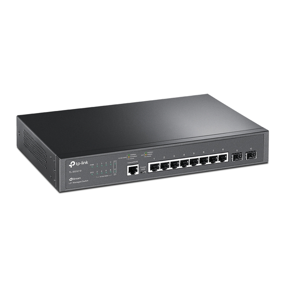
DHCPv6 servers. 2.3 Appearance Description 2.3.1 Front Panel The front panel of TL-SG3210 is shown as the following figure. Figure 2-1 Front Panel of TL-SG3210 The front panel of TL-SG3216 is shown as the following figure. Figure 2-2 Front Panel of TL-SG3216 The front panel of TL-SG3424 is shown as the following figure. - Page 18 SFP transceiver slots that are shared with the associated RJ45 ports. The associated two ports are referred to as “Combo” ports, which means they cannot be used simultaneously, otherwise only SFP ports work. TL-SG3210 features two individual SFP ports. Note:...
-
Page 19: Rear Panel
When the Speed LED is on, the port LED is indicating the data transmission rate. Name Status Indication The switch is powered on. Power The switch is powered off or power supply is abnormal. Flashing Power supply is abnormal. Flashing The switch works properly. - Page 20 AC power outlet. Make sure the voltage of the power supply meets the requirement of the input voltage (100-240V~ 50/60Hz 0.6A for TL-SG3210, 100-240V~ 50/60Hz 0.4A TL-SG3216, 100-240V~ 50/60Hz 0.5A TL-SG3424 and 100-240V~ 50/60Hz 5A for TL-SG3424P).
-
Page 21: Chapter 3 Login To The Switch
Chapter 3 Login to the Switch 3.1 Login To access the configuration utility, open a web-browser and type in the default address http://192.168.0.1 in the address field of the browser, then press the Enter key. Figure 3-1 Web-browser Tips: To log in to the switch, the IP address of your PC should be set in the same subnet addresses of the switch. - Page 22 Note: Clicking Apply can only make the new configurations effective before the switch is rebooted. If you want to keep the configurations effective even the switch is rebooted, please click Save Config. You are suggested to click Save Config before cutting off the power or rebooting the switch to avoid losing the new configurations.
-
Page 23: Chapter 4 System
Chapter 4 System The System module is mainly for system configuration of the switch, including four submenus: System Info, User Management, System Tools and Access Security. 4.1 System Info The System Info, mainly for basic properties configuration, can be implemented on System Summary, Device Description, System Time, Daylight Saving Time, System IP and System IPv6 pages. - Page 24 Indicates the SFP port is not connected to a device. Indicates the SFP port is at the speed of 1000Mbps. Indicates the SFP port is at the speed of 100Mbps. When the cursor moves on the port, the detailed information of the port will be displayed. Figure 4-2 Port Information Port Info ...
-
Page 25: Device Description
Bandwidth Utilization Select Rx to display the bandwidth utilization of receiving packets on this port. Select Tx to display the bandwidth utilization of sending packets on this port. 4.1.2 Device Description On this page you can configure the description of the switch, including device name, device location and system contact. -
Page 26: Daylight Saving Time
Choose the menu System →System Info →System Time to load the following page. Figure 4-5 System Time The following entries are displayed on this screen: Time Info Current System Displays the current date and time of the switch. Date: Current Time Displays the current time Source of the switch. - Page 27 Choose the menu System →System Info →Daylight Saving Time to load the following page. Figure 4-6 Daylight Saving Time The following entries are displayed on this screen: DST Config DST Status: Enable or disable the DST. Predefined Mode: Select a predefined DST configuration: USA: Second Sunday in March, 02:00 ~ First Sunday in ...
-
Page 28: System Ip
Note: When the DST is disabled, the predefined mode, recurring mode and date mode cannot be configured. When the DST is enabled, the default daylight saving time is of Europe in predefined mode. 4.1.5 System IP Each device in the network possesses a unique IP Address. You can log on to the Web management page to operate the switch using this IP Address. -
Page 29: System Ipv6
If the switch gets the IP address from DHCP server, you can see the configuration of the switch in the DHCP server; if DHCP option is selected but no DHCP server exists in the network, a few minutes later, the switch will restore the setting to the default. If DHCP or BOOTP option is selected, the switch will get network parameters dynamically from the Internet, which means that its IP address, subnet mask and default gateway cannot be configured. - Page 30 6. Enhanced neighbor discovery mechanism: The IPv6 neighbor discovery protocol is a group of Internet control message protocol version 6 (ICMPv6) messages that manages the information exchange between neighbor nodes on the same link. The group of ICMPv6 messages takes the place of Address Resolution Protocol (ARP) message, Internet Control Message Protocol version 4 (ICMPv4) router discovery message, and ICMPv4 redirection message to provide a series of other functions.
- Page 31 Multicast address: An identifier for a set of interfaces (typically belonging to different nodes), similar to an IPv4 multicast address. A packet sent to a multicast address is delivered to all interfaces identified by that address. There are no broadcast addresses in IPv6. Their function is superseded by multicast addresses.
- Page 32 For all IEEE 802 interface types (for example, Ethernet and FDDI interfaces), Interface IDs in the modified EUI-64 format are constructed in the following way: The first three octets (24 bits) are taken from the Organizationally Unique Identifier (OUI) of the 48-bit link-layer address (the MAC address) of the interface, the fourth and fifth octets (16 bits) are a fixed hexadecimal value of FFFE, and the last three octets (24 bits) are taken from the last three octets of the MAC address.
- Page 33 Figure 4-9 Link-local Address Format IPv6 devices must not forward packets that have link-local source or destination addresses to other links. Note: You can configure multiple IPv6 addresses per interface, but only one link-local address. IPv6 Neighbor Discovery The IPv6 neighbor discovery process uses ICMP messages and solicited-node multicast addresses to determine the link-layer address of a neighbor on the same network (local link), verify the reachability of a neighbor, and track neighboring devices.
- Page 34 Neighbor Reachability Detection After node A acquires the link-layer address of its neighbor node B, node A can verify whether node B is reachable according to NS and NA messages. Node A sends an NS message whose destination address is the IPv6 address of node B. ...
- Page 35 RAs are also sent in response to device solicitation messages. Device solicitation messages, which have a value of 133 in the Type field of the ICMP packet header, are sent by hosts at system startup or anytime needed so that the host can immediately autoconfigure without needing to wait for the next scheduled RA message.
- Page 36 You can configure the system’s administrative IPv6 address on this page. Choose the menu System →System Info →System IPv6 to load the following page. Figure 4-10 System IPv6 The following entries are displayed on this screen: Global Config IPv6: Enable/Disable IPv6 function globally on the switch.
- Page 37 Status: Displays the status of the link-local address. Normal: Indicates that the link-local address is normal. Try: Indicates that the link-local address may be newly configured. Repeat: Indicates that the link-local address is duplicate. It is illegal to access the switch using the IPv6 address(including link-local and global address).
-
Page 38: User Management
Status: Displays the status of the global address. Normal: Indicates that the global address is normal. Try: Indicates that the global address may be newly configured. Repeat: Indicates that the corresponding address is duplicate. It is illegal to access the switch using this address. Tips: After adding a global IPv6 address to your switch manually here, you can configure your PC’s global IPv6 address in the same subnet with the switch and login to the switch via its global IPv6... - Page 39 Choose the menu System →User Management →User Config to load the following page. Figure 4-12 User Config The following entries are displayed on this screen: User Info User Name: Create a name for users’ login. Access Level: Select the access level to login. Admin: Admin can edit, modify and view all the settings of ...
-
Page 40: System Tools
4.3 System Tools The System Tools function, allowing you to manage the configuration file of the switch, can be implemented on Config Restore, Config Backup, Firmware Upgrade, System Reboot and System Reset pages. 4.3.1 Config Restore On this page you can upload a backup configuration file to restore your switch to this previous configuration. -
Page 41: Firmware Upgrade
4.3.3 Firmware Upgrade The switch system can be upgraded via the Web management page. To upgrade the system is to get more functions and better performance. Go to http:// www.tp-link.com to download the updated firmware. Choose the menu System →System Tools →Firmware Upgrade to load the following page. -
Page 42: System Reboot
4.3.4 System Reboot On this page you can reboot the switch and return to the login page. Please save the current configuration before rebooting to avoid losing the configuration unsaved Choose the menu System →System Tools →System Reboot to load the following page. Figure 4-16 System Reboot Note: To avoid damage, please do not turn off the device while rebooting. - Page 43 Choose the menu System →Access Security →Access Control to load the following page. Figure 4-18 Access Control The following entries are displayed on this screen: Access Control Config Control Mode: Select the control mode for users to log on to the Web management page.
-
Page 44: Ssl Config
Session Config Session Timeout: If you do nothing with the Web management page within the timeout time, the system will log out automatically. If you want to reconfigure, please login again. Access User Number Select Enable/Disable the Number Control function. Number Control;... -
Page 45: Ssh Config
Choose the menu System → Access Security → SSL Config to load the following page. Figure 4-19 SSL Config The following entries are displayed on this screen: Global Config SSL: Select Enable/Disable the SSL function on the switch. Certificate Download ... - Page 46 an insecure network environment. It can encrypt all the transmission data and prevent the information in a remote management being leaked. Comprising server and client, SSH has two versions, V1 and V2 which are not compatible with each other. In the communication, SSH server and client can auto-negotiate the SSH version and the encryption algorithm.
- Page 47 Key Download Key Type: Select the type of SSH Key to download. The switch supports three types: SSH-1 RSA, SSH-2 RSA and SSH-2 DSA. Key File: Select the desired key file to download. Download: Click the Download button to download the desired key file to the switch.
- Page 48 2. Click the Open button in the above figure to log on to the switch. Enter the login user name and password, and then you can continue to configure the switch. Application Example 2 for SSH: Network Requirements 1. Log on to the switch via password authentication using SSH and the SSH function is enabled on the switch.
- Page 49 2. After the key is successfully generated, please save the public key and private key to the computer. 3. On the Web management page of the switch, download the public key file saved in the computer to the switch. Note: The key type should accord with the type of the key file.
- Page 50 4. After the public key is downloaded, please log on to the interface of PuTTY and enter the IP address for login. 5. Click Browse to download the private key file to SSH client software and click Open.
- Page 51 After successful authentication, please enter the login user name. If you log on to the switch without entering password, it indicates that the key has been successfully downloaded. Note: Following the steps above, you have already entered the User EXEC Mode of the switch. However, to configure the switch, you need a password to enter the Privileged EXEC Mode first.
-
Page 52: Chapter 5 Switching
Chapter 5 Switching Switching module is used to configure the basic functions of the switch, including four submenus: Port, LAG, Traffic Monitor and MAC Address. 5.1 Port The Port function, allowing you to configure the basic features for the port, is implemented on the Port Config, Port Mirror, Port Security, Port Isolation and Loopback Detection pages. -
Page 53: Port Mirror
Port: Displays the port number. Description: Give a description to the port for identification. Status: Allows you to Enable/Disable the port. When Enable is selected, the port can forward the packets normally. Speed and Duplex: Select the Speed and Duplex mode for the port. The device connected to the switch should be in the same Speed and Duplex mode with the switch. - Page 54 Choose the menu Switching → Port → Port Mirror to load the following page. Figure 5-2 Mirror Group List The following entries are displayed on this screen. Mirror Group List Group: Displays the mirror group number. Mirroring: Displays the mirroring port number. Mode: Displays the mirror mode, the value will be "Ingress"...
- Page 55 Click Edit to display the following figure. Figure 5-3 Port Mirror Config The following entries are displayed on this screen. Mirror Group Number: Select the mirror group number you want to configure. Mirroring Port Mirroring Port: Select the mirroring port number. Mirrored Port ...
-
Page 56: Port Security
Egress: Select Enable/Disable the Egress feature. When the Egress is enabled, the outgoing packets sent by the mirrored port will be copied to the mirroring port. LAG: Displays the LAG number which the port belongs to. The LAG member cannot be selected as the mirrored port or mirroring port. - Page 57 Choose the menu Switching → Port → Port Security to load the following page. Figure 5-4 Port Security The following entries are displayed on this screen: Port Security Select: Select the desired port for Port Security configuration. It is multi-optional.
-
Page 58: Port Isolation
Note: The Port Security function is disabled for the LAG port member. Only the port is removed from the LAG, will the Port Security function be available for the port. The Port Security function is disabled when the 802.1X function is enabled. 5.1.4 Port Isolation Port Isolation provides a method of restricting traffic flow to improve the network security by forbidding the port to forward packets to the ports that are not on its forward portlist. -
Page 59: Loopback Detection
Port Isolation List Port: Display the port number. Forward Portlist: Display the Forward Portlist. 5.1.5 Loopback Detection With loopback detection feature enabled, the switch can detect loops using loopback detection packets. When a loop is detected, the switch will display an alert or further block the corresponding port according to the port configuration. -
Page 60: Lag
The following entries are displayed on this screen: Global Config LoopbackDetection Here you can enable or disable Loopback Detection function Status: globally. Detection Interval: Set a Loopback Detection interval between 1 and 1000 seconds. By default, it’s 30 seconds. Automatic Recovery Time after which the blocked port would automatically recover to Time:... -
Page 61: Lag Table
For the member ports in an aggregation group, their basic configuration must be the same. The basic configuration includes STP, QoS, GVRP, VLAN, port attributes, MAC Address Learning mode and other associated settings. More details are explained below: If the ports, which are enabled for the GVRP, 802.1Q VLAN, Voice VLAN, STP, QoS, DHCP ... -
Page 62: Static Lag
The following entries are displayed on this screen: Global Config Hash Algorithm: Select the applied scope of Aggregate Arithmetic, which results in choosing a port to transfer the packets. • SRC MAC + DST MAC: When this option is selected, the Aggregate Arithmetic will apply to the source and destination MAC addresses of the packets. -
Page 63: Lacp Config
Choose the menu Switching → LAG → Static LAG to load the following page. Figure 5-8 Static LAG Config The following entries are displayed on this screen: LAG Config Group Number: Select a Group Number for the LAG. Description: Give a description to the LAG for identification. - Page 64 group. In an aggregation group, the port with smaller port priority will be considered as the preferred one. If the two port priorities are equal; the port with smaller port number is preferred. After an aggregation group is established, the selected ports can be aggregated together as one port to transmit packets.
-
Page 65: Traffic Monitor
Select: Select the desired port for LACP configuration. It is multi-optional. Port: Displays the port number. Admin Key: Specify an Admin Key for the port. The member ports in a dynamic aggregation group must have the same Admin Key. Port Priority: Specify a Port Priority for the port. - Page 66 Choose the menu Switching → Traffic Monitor → Traffic Summary to load the following page. Figure 5-10 Traffic Summary The following entries are displayed on this screen: Auto Refresh Auto Refresh: Allows you to Enable/Disable refreshing the Traffic Summary automatically.
-
Page 67: Traffic Statistics
Statistics: Click the Statistics button to view the detailed traffic statistics of the port. 5.3.2 Traffic Statistics Traffic Statistics screen displays the detailed traffic information of each port, which facilitates you to monitor the traffic and locate faults promptly. Choose the menu Switching → Traffic Monitor → Traffic Statistics to load the following page. Figure 5-11 Traffic Statistics The following entries are displayed on this screen: Auto Refresh... -
Page 68: Mac Address
transmitted on the port. The error frames are not counted in. Multicast: Displays the number of good multicast packets received or transmitted on the port. The error frames are not counted in. Unicast: Displays the number of good unicast packets received or transmitted on the port. -
Page 69: Address Table
Table 5-1 Types and features of Address Table This function includes four submenus: Address Table, Static Address, Dynamic Address and Filtering Address. 5.4.1 Address Table On this page, you can view all the information of the Address Table. Choose the menu Switching → MAC Address → Address Table to load the following page. Figure 5-12 Address Table The following entries are displayed on this screen: Search Option... -
Page 70: Static Address
Dynamic: This option allows the address table to display the dynamic address entries only. Filtering: This option allows the address table to display the filtering address entries only. Address Table MAC Address: Displays the MAC address learned by the switch. VLAN ID: Displays the corresponding VLAN ID of the MAC address. -
Page 71: Dynamic Address
VLAN ID: Enter the corresponding VLAN ID of the MAC address. Port: Select a port from the pull-down list to be bound. Search Option Search Option: Select a Search Option from the pull-down list and click the Search button to find your desired entry in the Static Address Table. MAC: Enter the MAC address of your desired entry. - Page 72 Choose the menu Switching → MAC Address → Dynamic Address to load the following page. Figure 5-14 Dynamic Address The following entries are displayed on this screen: Aging Config Auto Aging: Allows you to Enable/Disable the Auto Aging feature. Aging Time: Enter the Aging Time for the dynamic address.
-
Page 73: Filtering Address
Dynamic Address Table Select: Select the entry to delete the dynamic address or to bind the MAC address to the corresponding port statically. It is multi-optional. MAC Address: Displays the dynamic MAC Address. VLAN ID: Displays the corresponding VLAN ID of the MAC address. Port: Displays the corresponding port number of the MAC address. - Page 74 Choose the menu Switching → MAC Address → Filtering Address to load the following page. Figure 5-15 Filtering Address The following entries are displayed on this screen: Create Filtering Address MAC Address: Enter the MAC Address to be filtered. VLAN ID: Enter the corresponding VLAN ID of the MAC address.
- Page 75 Note: The MAC address in the Filtering Address Table cannot be added to the Static Address Table or bound to a port dynamically. This MAC address filtering function is not available if the 802.1X feature is enabled. Return to CONTENTS...
-
Page 76: Chapter 6 Vlan
Chapter 6 VLAN The traditional Ethernet is a data network communication technology based on CSMA/CD (Carrier Sense Multiple Access/Collision Detect) via shared communication medium. Through the traditional Ethernet, the overfull hosts in LAN will result in serious collision, flooding broadcasts, poor performance or even breakdown of the Internet. -
Page 77: Q Vlan
packets of different VLANs. The switch can analyze the received untagged packets on the port and match the packets with the MAC VLAN, Protocol VLAN and 802.1Q VLAN in turn. If a packet is matched, the switch will add a corresponding VLAN tag to it and forward it in the corresponding VLAN. - Page 78 (2) TRUNK: The TRUNK port can be added in multiple VLANs, and the egress rule of the port is TAG. The TRUNK port is generally used to connect the network devices for it cascaded can receive and forward the packets of multiple VLANs. When the packets are forwarded by the TRUNK port, its VLAN tag will not be changed.
-
Page 79: Vlan Config
IEEE 802.1Q VLAN function is implemented on the VLAN Config and Port Config pages. 6.1.1 VLAN Config On this page, you can view the current created 802.1Q VLAN. Choose the menu VLAN → 802.1Q VLAN → VLAN Config to load the following page. Figure 6-3 VLAN Table To ensure the normal communication of the factory switch, the default VLAN of all ports is set to VLAN1. - Page 80 Click Edit button to modify the settings of the corresponding VLAN. Click Create button to create a new VLAN. Figure 6-4 Create or Modify 802.1Q VLAN The following entries are displayed on this screen: VLAN Config VLAN ID: Enter the ID number of VLAN. Description: Give a description to the VLAN for identification.
-
Page 81: Port Config
Link Type: Displays the Link Type of the port. It can be reset on Port Config screen. Egress Rule: Select the Egress Rule for the VLAN port member. The default egress rule is UNTAG. • TAG: All packets forwarded by the port are tagged. The packets contain VLAN information. -
Page 82: Configuration Procedure
Select the Link Type from the pull-down list for the port. Link Type: • ACCESS: The ACCESS port can be added in a single VLAN, and the egress rule of the port is UNTAG. The PVID is same as the current VLAN ID. If the current VLAN is deleted, the PVID will be set to 1 by default. -
Page 83: Mac Vlan
Step Operation Description Modify/View VLAN. Optional. On the VLAN→802.1Q VLAN→VLAN Config page, click the Edit/Detail button to modify/view the information of the corresponding VLAN. Delete VLAN Optional. On the VLAN→802.1Q VLAN→VLAN Config page, select the desired entry to delete the corresponding VLAN by clicking the Delete button. -
Page 84: Protocol Vlan
The following entries are displayed on this screen: VLAN Table MAC Address: Enter the MAC address. Description: Give a description to the MAC address for identification. VLAN ID: Enter the ID number of the MAC VLAN. This VLAN should be one of the 802.1Q VLANs the ingress port belongs to. - Page 85 the data of specific protocol can be automatically assigned to the corresponding VLAN for transmission. The network administrator can manage network clients based on their specific applications and services through protocol VLAN. Encapsulation Format of Ethernet Data This section simply introduces the common used encapsulation format of Ethernet data to understand the procedure for the switch to identify the protocol of packets.
- Page 86 The Procedure for the Switch to Identify Packet Protocol The Implementation of Protocol VLAN This switch can match packets through protocol template and transmit packets in the specific VLAN according to the protocol. Protocol template, comprising encapsulation format and protocol type, is the standard to determine the protocol which a packet belongs to.
-
Page 87: Protocol Group Table
The packet in Protocol VLAN is processed in the following way: VLAN packets are processed in the following way: When receiving an untagged packet, the switch matches the packet with the current Protocol VLAN. If the packet is matched, the switch will add a corresponding Protocol VLAN tag to it. If no Protocol VLAN is matched, the switch will add a tag to the packet according to the PVID of the received port. -
Page 88: Protocol Template
Choose the menu VLAN → Protocol VLAN → Protocol Group to load the following page. Figure 6-9 Create Protocol VLAN The following entries are displayed on this screen: Protocol Group Config Protocol: Select the defined protocol template. VLAN ID: Enter the ID number of the Protocol VLAN. -
Page 89: Application Example For 802.1Q Vlan
The following entries are displayed on this screen: Create Protocol Template Protocol Name: Give a name for the Protocol Template. Ether Type: Enter the Ethernet protocol type field in the protocol template. Frame Type: Select a Frame Type for the Protocol Template. Protocol Template Table ... - Page 90 Switch B is connecting to PC B and Server A; PC A and Server A is in the same VLAN; PC B and Server B is in the same VLAN; PCs in the two VLANs cannot communicate with each other. ...
-
Page 91: Application Example For Mac Vlan
6.5 Application Example for MAC VLAN Network Requirements Switch A and switch B are connected to meeting room A and meeting room B respectively, and the two rooms are for all departments; Notebook A and Notebook B, special for meeting room, are of two different departments; ... -
Page 92: Application Example For Protocol Vlan
Configure Switch B Step Operation Description Configure Required. On VLAN→802.1Q VLAN →Port Config page, configure Link Type of the the link type of Port 21 and Port 22 as GENERAL and TRUNK ports respectively. Create VLAN10 Required. On VLAN→802.1Q VLAN→VLAN Config page, create a VLAN with its VLAN ID as 10, owning Port 21 and Port 22, and configure the egress rule of Port 21 as Untag. - Page 93 Network Diagram Configuration Procedure Configure Switch A Step Operation Description Configure Required. On VLAN→802.1Q VLAN →Port Config page, configure Link Type of the the link type of Port 11 and Port 13 as ACCESS, and configure the link ports type of Port 12 as GENERAL.
-
Page 94: Gvrp
Step Operation Description Create Protocol Required. On VLAN →Protocol VLAN →Protocol Template page, Template configure the protocol template practically. E.g. the IP network packets are encapsulated in Ethernet II format and its Ether Type is 0800; the AppleTalk network packets are encapsulated in SNAP format and its PID is 809B. - Page 95 Join Timer: To transmit the Join messages reliably to other entities, a GARP entity sends • each Join message two times. The Join timer is used to define the interval between the two sending operations of each Join message. • Leave Timer: When a GARP entity expects to deregister a piece of attribute information, it sends out a Leave message.
- Page 96 Choose the menu VLAN →GVRP to load the following page. Figure 6-11 GVRP Config Note: If the GVRP feature is enabled for a member port of LAG, please ensure all the member ports of this LAG are set to be in the same status and registration mode. The following entries are displayed on this screen: Global Config ...
- Page 97 • Forbidden: In this mode, a port cannot register/deregister VLANs. It only propagates VLAN 1 information. LeaveAll Timer: Once the LeaveAll Timer is set, the port with GVRP enabled can send a LeaveAll message after the timer times out, so that other GARP ports can re-register all the attribute information.
-
Page 98: Chapter 7 Spanning Tree
Chapter 7 Spanning Tree STP (Spanning Tree Protocol), subject to IEEE 802.1D standard, is to disbranch a ring network in the Data Link layer in a local network. Devices running STP discover loops in the network and block ports by exchanging information, in that way, a ring network can be disbranched to form a tree-topological ring-free network to prevent packets from being duplicated and forwarded endlessly in the network. - Page 99 Figure 7-1 Basic STP diagram STP Timers Hello Time: Hello Time ranges from 1 to 10 seconds. It specifies the interval to send BPDU packets. It is used to test the links. Max. Age: Max. Age ranges from 6 to 40 seconds. It specifies the maximum time the switch can wait without receiving a BPDU before attempting to reconfigure.
- Page 100 Comparing BPDUs Each switch sends out configuration BPDUs and receives a configuration BPDU on one of its ports from another switch. The following table shows the comparing operations. Step Operation If the priority of the BPDU received on the port is lower than that of the BPDU if of the port itself, the switch discards the BPDU and does not change the BPDU of the port.
- Page 101 The condition for the root port to transit its port state rapidly: The old root port of the switch stops forwarding data and the designated port of the upstream switch begins to forward data. The condition for the designated port to transit its port state rapidly: The designated port is ...
- Page 102 The following figure shows the network diagram in MSTP. Figure 7-2 Basic MSTP diagram MSTP MSTP divides a network into several MST regions. The CST is generated between these MST regions, and multiple spanning trees can be generated in each MST region. Each spanning tree is called an instance.
-
Page 103: Stp Config
The following diagram shows the different port roles. Figure 7-3 Port roles The Spanning Tree module is mainly for spanning tree configuration of the switch, including four submenus: STP Config, Port Config, MSTP Instance and STP Security. 7.1 STP Config The STP Config function, for global configuration of spanning trees on the switch, can be implemented on STP Config and STP Summary pages. - Page 104 Choose the menu Spanning Tree →STP Config →STP Config to load the following page. Figure 7-4 STP Config The following entries are displayed on this screen: Global Config STP: Select Enable/Disable STP function globally on the switch. Version: Select the desired STP version on the switch. ...
-
Page 105: Stp Summary
Max Hops: Enter a value from 1 to 40 to set the maximum number of hops that occur in a specific region before the BPDU is discarded. The default value is 20 hops. Note: The forward delay parameter and the network diameter are correlated. A too small forward delay parameter may result in temporary loops. -
Page 106: Port Config
Choose the menu Spanning Tree →STP Config →STP Summary to load the following page. Figure 7-5 STP Summary 7.2 Port Config On this page you can configure the parameters of the ports for CIST... - Page 107 Choose the menu Spanning Tree →Port Config to load the following page. Figure 7-6 Port Config The following entries are displayed on this screen: Port Config Port Select: Click the Select button to quick-select the corresponding port based on the port number you entered. Select: Select the desired port for STP configuration.
-
Page 108: Mstp Instance
Designated Port: Indicates the port that forwards packets to a downstream network segment or switch. Master Port: Indicates the port that connects a MST region to the common root. The path from the master port to the common root is the shortest path between this MST region and the common root. -
Page 109: Instance Config
Choose the menu Spanning Tree → MSTP Instance → Region Config to load the following page. Figure 7-7 Region Config The following entries are displayed on this screen: Region Config Region Name: Create a name for MST region identification using up to 32 characters. Revision: Enter the revision from 0 to 65535 for MST region identification. - Page 110 Choose the menu Spanning Tree → MSTP Instance → Instance Config to load the following page. Figure 7-8 Instance Config The following entries are displayed on this screen: Instance Table Instance ID Select: Click the Select button to quick-select the corresponding Instance ID based on the ID number you entered.
-
Page 111: Instance Port Config
VLAN-Instance Mapping VLAN ID: Enter the desired VLAN ID. After modification here, the new VLAN ID will be added to the corresponding instance ID and the previous VLAN ID won’t be replaced. Instance ID: Enter the corresponding instance ID. Note: In a network with both GVRP and MSTP enabled, GVRP packets are forwarded along the CIST. - Page 112 The following entries are displayed on this screen: Port Config Instance ID: Select the desired instance ID for its port configuration. Port Select: Click the Select button to quick-select the corresponding port based on the port number you entered. Select: Select the desired port to specify its priority and path cost.
-
Page 113: Stp Security
7.4 STP Security Configuring protection function for devices can prevent devices from any malicious attack against STP features. The STP Security function can be implemented on Port Protect and TC Protect pages. Port Protect function is to prevent the devices from any malicious attack against STP features. 7.4.1 Port Protect On this page you can configure loop protect feature, root protect feature, TC protect feature, BPDU protect feature and BPDU filter feature for ports. - Page 114 Normally these ports do not receive BPDUs, but if a user maliciously attacks the switch by sending BPDUs, network topology jitter occurs. To prevent this attack, MSTP provides BPDU protect function. With this function enabled on the switch, the switch shuts down the edge ports that receive BPDUs and reports these cases to the administrator.
-
Page 115: Tc Protect
Port: Displays the port number of the switch. Loop Protect: Loop Protect is to prevent the loops in the network brought by recalculating STP because of link failures and network congestions. Root Protect: Root Protect is to prevent wrong network topology change caused by the role change of the current legal root bridge. - Page 116 On Spanning Tree→STP Config→Port Config page, enable MSTP function for the port. Configure the region name and On Spanning Tree→MSTP Instance→Region Config the revision of MST region page, configure the region as TP-LINK and keep the default revision setting. Configure VLAN-to-Instance Spanning Tree→MSTP...
- Page 117 Step Operation Description Configure the region name and On Spanning Tree→MSTP Instance→Region the revision of MST region Config page, configure the region as TP-LINK and keep the default revision setting. Configure VLAN-to-Instance On Spanning Tree→MSTP Instance→Instance mapping table of the MST...
- Page 118 On Spanning Tree→STP Config→Port Config page, enable MSTP function for the port. Configure the region name and On Spanning Tree→MSTP Instance→Region Config page, configure the region as TP-LINK and the revision of MST region keep the default revision setting. On Spanning Tree→MSTP Instance→Instance...
- Page 119 Suggestion for Configuration Enable TC Protect function for all the ports of switches. Enable Root Protect function for all the ports of root bridges. Enable Loop Protect function for the non-edge ports. Enable BPDU Protect function or BPDU Filter function for the edge ports which are connected to the PC and server.
-
Page 120: Chapter 8 Multicast
Chapter 8 Multicast Multicast Overview In the network, packets are sent in three modes: unicast, broadcast and multicast. In unicast, the source server sends separate copy information to each receiver. When a large number of users require this information, the server must send many pieces of information with the same content to the users. - Page 121 IPv4 Multicast Address 1. IPv4 Multicast IP Address: As specified by IANA (Internet Assigned Numbers Authority), Class D IP addresses are used as destination addresses of multicast packets. The multicast IP addresses range from 224.0.0.0~239.255.255.255. The following table displays the range and description of several special multicast IP addresses.
- Page 122 0XFF at the start of the address identifies the address as being a multicast address. Flags have 4 bits: The high-order flag is reserved, and must be initialized to 0. R: Set to 0 to indicate this IPv6 multicast address does not contain an embedded RP address;...
- Page 123 Reserved Multicast Addresses: Address Indication FF01::1 All interface-local IPv6 nodes FF02::1 All link-local IPv6 nodes FF01::2 All interface-local IPv6 routers FF02::2 All link-local IPv6 routers FF05::2 All site-local IPv6 routers FF0X:: X ranges from 0 to F. These multicast addresses are reserved and shall never be assigned to any multicast group.
-
Page 124: Igmp Snooping
Multicast Address Table The switch is forwarding multicast packets based on the multicast address table. As the transmission of multicast packets cannot span the VLAN, the first part of the multicast address table is VLAN ID, based on which the received multicast packets are forwarded in the VLAN owning the receiving port. - Page 125 if the multicast groups contain any member. When receiving IGMP leave message, the receiving port of the router will send IGMP group-specific-query message to the multicast group and the switch will forward IGMP group-specific-query message to check if other members in the multicast group of the port need this multicast.
-
Page 126: Snooping Config
The IGMP Snooping function can be implemented on the following pages: Snooping Config, VLAN Config, Port Config, IP-Range, Multicast VLAN, Static Multicast IP and Packet Statistics. 8.1.1 Snooping Config To configure the IGMP Snooping on the switch, please firstly configure IGMP global configuration and related parameters on this page. - Page 127 Choose the menu Multicast→IGMP Snooping→VLAN Config to load the following page. Figure 8-6 VLAN Config The following entries are displayed on this screen: VLAN Config VLAN ID: Enter the VLAN ID to enable IGMP Snooping for the desired VLAN. Router Port Time: Specify the aging time of the router port.
-
Page 128: Port Config
Member Port Time: Displays the member port time of the VLAN. Leave Time: Displays the leave time of the VLAN. Router Port: Displays the router port of the VLAN. Note: The settings here will be invalid when multicast VLAN is enabled Configuration procedure: Step Operation Description... -
Page 129: Ip-Range
The following entries are displayed on this screen: Port Config Port Select: Click the Select button to quick-select the corresponding port based on the port number you entered. Select: Select the desired port for IGMP Snooping feature configuration. It is multi-optional. -
Page 130: Multicast Vlan
Choose the menu Multicast→IGMP Snooping→IP-Range to load the following page. Figure 8-8 Multicast Filter The following entries are displayed on this screen: Create IP-Range IP Range ID: Enter the IP-range ID. Start Multicast IP: Enter start multicast IP of the IP-range you set. End Multicast IP: Enter end multicast IP of the IP-range you set. - Page 131 Before configuring a multicast VLAN, you should firstly configure a VLAN as multicast VLAN and add the corresponding ports to the VLAN on the 802.1Q VLAN page. If the multicast VLAN is enabled, the multicast configuration for other VLANs on the VLAN Config page will be invalid, that is, the multicast streams will be transmitted only within the multicast VLAN.
- Page 132 Configure the link type of the router port in the multicast VLAN as TRUNK or configure the egress rule as TAG and the link type as GENERAL otherwise all the member ports in the multicast VLAN cannot receive multicast streams. After a multicast VLAN is created, all the IGMP packets will be processed only within the multicast VLAN.
-
Page 133: Static Multicast Ip
Network Diagram Configuration Procedure Step Operation Description Create VLANs Create three VLANs with the VLAN ID 3, 4 and 5 respectively, and specify the description of VLAN3 as Multicast VLAN on VLAN→802.1Q VLAN page. Configure ports On VLAN→802.1Q VLAN function pages. For port 3, configure its link type as GENERAL and its egress rule as TAG, and add it to VLAN3, VLAN4 and VLAN5. -
Page 134: Packet Statistics
Choose the menu Multicast→IGMP Snooping→Static Multicast IP to load the following page. Figure 8-10 Static Multicast IP Table The following entries are displayed on this screen: Create Static Multicast Multicast IP: Enter static multicast IP address. VLAN ID: Enter the VLAN ID of the multicast IP. Forward Port: Enter the forward port of the multicast group. - Page 135 Choose the menu Multicast→IGMP Snooping→Packet Statistics to load the following page. Figure 8-11 Packet Statistics The following entries are displayed on this screen: Auto Refresh Auto Refresh: Select Enable/Disable auto refresh feature. Refresh Period: Enter the time from 3 to 300 in seconds to specify the auto refresh period.
-
Page 136: Mld Snooping
Error Packet: Displays the number of error packets the port received. 8.2 MLD Snooping MLD Snooping Multicast Listener Discovery(MLD)snooping is applied for efficient distribution of IPv6 multicast data to clients and routers in a Layer 2 network. With MLD snooping, IPv6 multicast data is selectively forwarded to a list of ports that want to receive the data, instead of being flooded to all ports in a VLAN. -
Page 137: Global Config
MLD Snooping Process General Query The MLD router regularly sends MLD general queries to query if the multicast groups contain any members. When receiving MLD general queries, the switch will forward them to all other ports in the VLAN. The receiving port will be processed: if the receiving port is not a router port yet, it will be added to the router port list with its router port aging time specified;... - Page 138 Chose the menu Multicast→MLD Snooping→Global Config to load the following page. The following entries are displayed on this screen: Global Config MLD Snooping: Enable or disable MLD Snooping function globally. Report Message Enable or disable Report Message Suppression function globally. Suppression: If this function is enabled, the first Report Message from the listener will forward to the router ports while the subsequent...
-
Page 139: Vlan Config
Multicast VLAN: Enable or disable multicast VLAN function. When multicast VLAN is enabled, all multicast data will forward in this VLAN if this port belongs to the VLAN. Multicast VLAN ID: Enter the multicast VLAN ID. Note: 1. When Unknown Multicast Filter is configured, the Unknown Multicast function in IGMP Snooping is also configured at the same time. - Page 140 The following entries are displayed on this screen: VLAN Config VLAN ID: Enter the VLAN ID you want to configure. Router Port Aging Enter the router port aging time for this VLAN. It will override the Time: global configured aging time. Member Port Aging Enter the member port aging time for this VLAN.
-
Page 141: Filter Config
Dynamic Router Displays the dynamic router ports of this VLAN. Ports: Note: 1. The MLD snooping function in a VLAN will take effect when global MLD Snooping function is enabled in 8.2.1 Global Config and the VLAN is created in Chapter 6 VLAN. -
Page 142: Port Config
8.2.4 Port Config On this page you can configure MLD Snooping function with each single port. Choose the menu Multicast→MLD Snooping→Port Config to load the following page. The following entries are displayed on this screen: Port Config Select: Select the port you want to configure. Port: Displays the port number. -
Page 143: Querier Config
Choose the menu Multicast→MLD Snooping→Static Multicast to load the following page. The following entries are displayed on this screen: Static Multicast Config VLAN ID: Enter the VLAN ID. Multicast IP: Enter the multicast IP address. Member Ports: Enter the member ports of the static multicast group. Static Multicast List ... -
Page 144: Packet Statistics
The following entries are displayed on this screen: Querier Config VLAN ID: Enter the VLAN ID which you want to start Querier. Maximum Response Enter the value of Maximum Response Time field of Time: the Query message. Query Interval: Enter the Query message interval time. - Page 145 Choose the menu Multicast→MLD Snooping→Packet Statistics to load the following page. The following entries are displayed on this screen: Auto Fresh Auto Fresh: Select Enable/Disable auto fresh feature. Fresh Period: Enter the time from 3 to 300 seconds to specify the auto fresh period.
-
Page 146: Multicast Table
Error Packet: Displays the number of error packets which the switch has received. 8.3 Multicast Table In a network, receivers can join different multicast groups appropriate to their needs. The switch forwards multicast streams based on IPv4/IPv6 multicast address table. The Multicast Table function is implemented on the IPv4 Multicast Table and IPv6 Multicast Table pages. -
Page 147: Ipv6 Multicast Table
8.3.2 IPv6 Multicast Table This page displays the multicast groups which already on the switch. Choose the menu Multicast→Multicast Table→IPv6 Multicast Table to load the following page. The following entries are displayed on this screen: Search Option Multicast IP: Enter the multicast IP address the desired entry must carry. -
Page 148: Chapter 9 Qos
Chapter 9 QoS QoS (Quality of Service) functions to provide different quality of service for various network applications and requirements and optimize the bandwidth resource distribution so as to provide a network service experience of a better quality. This switch classifies the ingress packets, maps the packets to different priority queues and then forwards the packets according to specified scheduling algorithms to implement QoS function. - Page 149 2. 802.1P Priority Figure 9-2 802.1Q frame As shown in the figure above, each 802.1Q Tag has a Pri field, comprising 3 bits. The 3-bit priority field is 802.1p priority in the range of 0 to 7. 802.1P priority determines the priority of the packets based on the Pri value.
- Page 150 Figure 9-4 SP-Mode WRR-Mode: Weight Round Robin Mode. In this mode, packets in all the queues are sent in order based on the weight value for each queue and every queue can be assured of a certain service time. The weight value indicates the occupied proportion of the resource. WRR queue overcomes the disadvantage of SP queue that the packets in the queues with lower priority cannot get service for a long time.
-
Page 151: Diffserv
The QoS module is mainly for traffic control and priority configuration, including three submenus: DiffServ, Bandwidth Control and Voice VLAN. 9.1 DiffServ This switch classifies the ingress packets, maps the packets to different priority queues and then forwards the packets according to specified scheduling algorithms to implement QoS function. This switch implements three priority modes basing on port, on 802.1P and on DSCP, and supports four queue scheduling algorithms. -
Page 152: Dscp Priority
Configuration Procedure: Step Operation Description Select the port priority Required. On QoS→DiffServ→Port Priority page, configure the port priority. Configure mapping Required. On QoS→DiffServ→802.1P/CoS mapping relation between the CoS page, configure the mapping relation between the CoS priority and TC and TC. Select a schedule mode Required. -
Page 153: P/Cos Mapping
The following entries are displayed on this screen: DSCP Priority Config DSCP Priority: Select Enable or Disable DSCP Priority. Priority Level DSCP: Indicates the priority determined by the DS region of IP datagram. It ranges from 0 to 63. Priority: Indicates the 802.1P priority the packets with tag are mapped to. -
Page 154: Schedule Mode
The following entries are displayed on this screen: Priority and CoS-mapping Config Tag-id/Cos-id: Indicates the precedence level defined by IEEE802.1P and the CoS ID. Queue TC-id: Indicates the priority level of egress queue the packets with tag and CoS-id are mapped to. The priority levels of egress queue are labeled as TC0, TC1, TC2 and TC3. -
Page 155: Bandwidth Control
SP+WRR-Mode: Strict-Priority + Weight Round Robin Mode. In this mode, this switch provides two scheduling groups, SP group and WRR group. Queues in SP group and WRR group are scheduled strictly based on strict-priority mode while the queues inside WRR group follow the WRR mode. -
Page 156: Storm Control
The following entries are displayed on this screen: Rate Limit Config Port Select: Click the Select button to quick-select the corresponding port based on the port number you entered. Select: Select the desired port for Rate configuration. It is multi-optional. Port: Displays the port number of the switch. - Page 157 Choose the menu QoS →Bandwidth Control →Storm Control to load the following page. Figure 9-11 Storm Control The following entries are displayed on this screen: Storm Control Config Port Select: Click the Select button to quick-select the corresponding port based on the port number you entered.
-
Page 158: Voice Vlan
9.3 Voice VLAN Voice VLANs are configured specially for voice data stream. By configuring Voice VLANs and adding the ports with voice devices attached to voice VLANs, you can perform QoS-related configuration for voice data, ensuring the transmission priority of voice data stream and voice quality. - Page 159 Port Voice VLAN Voice Link type of the port and processing mode Mode Stream Type Automatic Mode voice ACCESS: Not supported. stream TRUNK: Supported. The default VLAN of the port cannot be voice VLAN. GENERAL: Supported. The default VLAN of the port cannot be voice VLAN and the egress rule of the access port in the voice VLAN should be TAG.
-
Page 160: Global Config
Note: Do not transmit voice stream together with other business packets in the voice VLAN except for some special requirements. The Voice VLAN function can be implemented on Global Config, Port Config and OUI Config pages. 9.3.1 Global Config On this page, you can configure the global parameters of the voice VLAN, including VLAN ID, aging time, the transmission priority of the voice packets and so on. - Page 161 Choose the menu QoS →Voice VLAN →Port Config to load the following page. Figure 9-13 Port Config Note: To enable voice VLAN function for the LAG member port, please ensure its member state accords with its port mode. If a port is a member port of voice VLAN, changing its port mode to be “Auto” will make the port leave the voice VLAN and will not join the voice VLAN automatically until it receives voice streams.
-
Page 162: Oui Config
Security Mode: Configure the security mode for forwarding packets. Disable: All packets are forwarded. Enable: Only voice data are forwarded. Member State: Displays the state of the port in the current voice VLAN. LAG: Displays the LAG number which the port belongs to. 9.3.3 OUI Config The switch supports OUI creation and adds the MAC address of the special voice device to the OUI table of the switch. - Page 163 Description: Displays the description of the OUI. Configuration Procedure of Voice VLAN: Step Operation Description Required. On VLAN→802.1Q VLAN→Port Config page, Configure the link type of the port configure the link type of ports of the voice device. Required. On VLAN→802.1Q VLAN→Port Config page, click Create VLAN the Create button to create a VLAN.
-
Page 164: Chapter 10 Poe
Chapter 10 PoE Note: Only TL-SG3424P supports PoE function. PoE (Power over Ethernet) technology describes a system to transmit electrical power along with data to remote devices over standard twisted-pair cable in an Ethernet network. It is especially useful for supplying power to IP telephones, wireless LAN access points, cameras and so on. Composition ... -
Page 165: Poe Config
PoE Config, mainly for PoE attributes configuration, is implemented on PoE Config and PoE Time-Range ages. 10.1.1 PoE Config On this page, you can configure the parameters to implement PoE function. Choose the menu PoE→PoE Config→PoE Config to load the following page. Figure 10-1 PoE Config The following items are displayed on this screen: Global Config... -
Page 166: Poe Profile
Port: Displays the port number. PoE Status: Select to disable/enable the PoE feature for the corresponding port. If set enable, the corresponding port can supply power to the linked PD (Powered Device). PoE Priority: The priority levels include High, Middle and Low in descending order. -
Page 167: Poe Time-Range
The following items are displayed on this screen: Create PoE Profile Profile Name: Enter the name of the profile. PoE Status: Select to the enable/disable PoE feature for the corresponding port. If set enable, the port may supply power to the linked PD (Power Device). -
Page 168: Poe Time-Range Create
The following items are displayed on this screen: Time-Range Table Select: Select the desired entry to delete the corresponding time-range. Index: Displays the index of the time-range. Time-Range Name: Displays the name of the time-range. Slice: Displays the time-slice of the time-range. Mode: Displays the mode the time-range adopts. -
Page 169: Poe Holiday Config
Week: Select Week to configure week time-range. The port based on this time-range will supply power based on this time-range when the system time is within the week time-range. Create Time-Slice Start Time: Set the start time of the time-slice. End Time: Set the end time of the time-slice. - Page 170 Holiday Name: Displays the name of the holiday. Start Date: Displays the start date of the holiday. End Date: Displays the end date of the holiday. Return to CONTENTS...
-
Page 171: Chapter 11 Acl
Chapter 11 ACL ACL (Access Control List) is used to filter packets by configuring match rules and process policies of packets in order to control the access of the illegal users to the network. Besides, ACL functions to control traffic flows and save network resources. It provides a flexible and secured access control policy and facilitates you to control the network security. -
Page 172: Time-Range Create
11.1.2 Time-Range Create On this page you can create time-ranges. Choose the menu ACL→Time-Range→Time-Range Create to load the following page. Figure 11-2 Time-Range Create Note: To successfully configure time-ranges, please firstly specify time-slices and then time-ranges. The following entries are displayed on this screen: Create Time-Range ... -
Page 173: Holiday Config
End Time: Displays the end time of the time-slice. Delete: Click the Delete button to delete the corresponding time-slice. 11.1.3 Holiday Config Holiday mode is applied as a different secured access control policy from the week mode. On this page you can define holidays according to your work arrangement. Choose the menu ACL→Time-Range→Holiday Config to load the following page. -
Page 174: Acl Summary
11.2.1 ACL Summary On this page, you can view the current ACLs configured in the switch. Choose the menu ACL→ACL Config→ACL Summary to load the following page. Figure 11-4 ACL Summary The following entries are displayed on this screen: Search Option ... -
Page 175: Mac Acl
11.2.3 MAC ACL MAC ACLs analyze and process packets based on a series of match conditions, which can be the source MAC addresses, destination MAC addresses, VLAN ID, and EtherType carried in the packets. Choose the menu ACL→ACL Config→MAC ACL to load the following page. Figure11-6 Create MAC Rule The following entries are displayed on this screen: Create MAC ACL... -
Page 176: Standard-Ip Acl
11.2.4 Standard-IP ACL Standard-IP ACLs analyze and process data packets based on a series of match conditions, which can be the source IP addresses and destination IP addresses carried in the packets. Choose the menu ACL→ACL Config→Standard-IP ACL to load the following page. Figure11-7 Create Standard-IP Rule The following entries are displayed on this screen: Create Standard-IP ACL... - Page 177 Choose the menu ACL→ACL Config→Extend-IP ACL to load the following page. Figure11-8 Create Extend-IP Rule The following entries are displayed on this screen: Create Extend-IP ACL ACL ID: Select the desired Extend-IP ACL for configuration. Rule ID: Enter the rule ID. Operation: Select the operation for the switch to process packets which match the rules.
-
Page 178: Policy Config
IP ToS: Enter the IP-ToS contained in the rule. IP Pre: Enter the IP Precedence contained in the rule. Time-Range: Select the time-range for the rule to take effect. 11.3 Policy Config A Policy is used to control the data packets those match the corresponding ACL rules by configuring ACLs and actions together for effect. -
Page 179: Action Create
Choose the menu ACL→Policy Config→Policy Create to load the following page. Figure 11-10 Create Policy The following entries are displayed on this screen: Create Policy Policy Name: Enter the name of the policy. 11.3.3 Action Create On this page you can add ACLs and create corresponding actions for the policy. Choose the menu ACL→Policy Config→Action Create to load the following page. -
Page 180: Policy Binding
S-Condition: Select S-Condition to limit the transmission rate of the data packets in the policy. Rate: Specify the forwarding rate of the data packets those match the corresponding ACL. Out of Band: Specify the disposal way of the data packets those ... -
Page 181: Port Binding
Index: Displays the index of the binding policy. Policy Name: Displays the name of the binding policy. Interface: Displays the port number or VLAN ID bound to the policy. Direction: Displays the binding direction. 11.4.2 Port Binding On this page you can bind a policy to a port. Choose the menu ACL→Policy Binding→Port Binding to load the following page. -
Page 182: Application Example For Acl
Choose the menu ACL→Policy Binding→VLAN Binding to load the following page. Figure11-14 Bind the policy to the VLAN The following entries are displayed on this screen: VLAN-Bind Config Policy Name: Select the name of the policy you want to bind. VLAN ID: Enter the ID of the VLAN you want to bind. - Page 183 3. The staff of the marketing department can access to the Internet all day but cannot visit the forum during the working time. 4. The R&D department and marketing department cannot communicate with each other. Network Diagram Configuration Procedure ...
- Page 184 Step Operation Description Configure On ACL→ACL Config→ACL Create page, create ACL 100. requirement On ACL→ACL Config→Standard-IP ACL page, select ACL 100, and 4 create Rule 1, configure operation as Deny, configure S-IP as 10.10.70.1 and mask as 255.255.255.0, configure D-IP as 10.10.50.1 and mask as 255.255.255.0, configure the time-range as No Limit.
-
Page 185: Chapter 12 Network Security
Chapter 12 Network Security Network Security module is to provide the multiple protection measures for the network security, including four submenus: IP-MAC Binding, ARP Inspection, DoS Defend and 802.1X. Please configure the functions appropriate to your need. 12.1 IP-MAC Binding The IP-MAC Binding function allows you to bind the IP address, MAC address, VLAN ID and the connected Port number of the Host together. - Page 186 The following entries are displayed on this screen: Search Option Source: Select a Source from the pull-down list and click the Search button to view your desired entry in the Binding Table. All: All the bound entries will be displayed. •...
-
Page 187: Manual Binding
Among the conflicting entries with the same Source priority, only the last added or edited one will take effect. 12.1.2 Manual Binding You can manually bind the IP address, MAC address, VLAN ID and the Port number together in the condition that you have got the related information of the Hosts in the LAN. Choose the menu Network Security→IP-MAC Binding→Manual Binding to load the following page. -
Page 188: Arp Scanning
Protect Type: Displays the Protect Type of the entry. Collision: Displays the Collision status of the entry. Warning: Indicates that the collision may be • caused by the MSTP function. • Critical: Indicates that the entry has a collision with the other entries. 12.1.3 ARP Scanning ARP (Address Resolution Protocol) is used to analyze and map IP addresses to the corresponding MAC addresses so that packets can be delivered to their destinations correctly. -
Page 189: Dhcp Snooping
Figure 12-4 ARP Scanning The following entries are displayed on this screen: Scanning Option Start IP Address: Specify the Start IP Address. End IP Address: Specify the End IP Address. VLAN ID: Enter the VLAN ID. If blank, the switch will send the untagged packets for scanning. - Page 190 network configuration protocol optimized and developed based on the BOOTP, functions to solve the above mentioned problems. DHCP Working Principle DHCP works via the “Client/Server” communication mode. The Client applies to the Server for configuration. The Server assigns the configuration information, such as the IP address, to the Client, so as to reach a dynamic employ of the network source.
- Page 191 The most Clients obtain the IP addresses dynamically, which is illustrated in the following figure. Figure 12-6 Interaction between a DHCP client and a DHCP server (1) DHCP-DISCOVER Stage: The Client broadcasts the DHCP-DISCOVER packet to find the DHCP Server. (2)...
- Page 192 supported Option 82 also can set the distribution policy of IP addresses and the other parameters according to the Option 82, providing more flexible address distribution way. Option 82 can contain 255 sub-options at most. If Option 82 is defined, at least a sub-option should be defined.
- Page 193 DHCP Snooping feature prevents the network from the DHCP Server Cheating Attack by discarding the DHCP packets on the distrusted port, so as to enhance the network security. Choose the menu Network Security→IP-MAC Binding→DHCP Snooping to load the following page. Figure 12-8 DHCP Snooping Note: If you want to enable the DHCP Snooping feature for the member port of LAG, please ensure the...
- Page 194 The following entries are displayed on this screen: DHCP Snooping Config DHCP Snooping: Enable/Disable the DHCP Snooping function globally. Global Flow Control: Select the value to specify the maximum amount of DHCP messages that can be forwarded by the switch per second. The excessive massages will be discarded.
-
Page 195: Arp Inspection
Decline Protect: Select Enable/Disable the Decline Protect feature. LAG: Displays the LAG to which the port belongs to. 12.2 ARP Inspection According to the ARP Implementation Procedure stated in 12.1.3 ARP Scanning, it can be found that ARP protocol can facilitate the Hosts in the same network segment to communicate with one another or access to external network via Gateway. - Page 196 Figure 12-10 ARP Attack – Cheating Gateway As the above figure shown, the attacker sends the fake ARP packets of Host A to the Gateway, and then the Gateway will automatically update its ARP table after receiving the ARP packets. When the Gateway tries to communicate with Host A in LAN, it will encapsulate this false destination MAC address for packets, which results in a breakdown of the normal communication.
- Page 197 Figure 12-11 ARP Attack – Cheating Terminal Hosts As the above figure shown, the attacker sends the fake ARP packets of Host A to Host B, and then Host B will automatically update its ARP table after receiving the ARP packets. When Host B tries to communicate with Host A, it will encapsulate this false destination MAC address for packets, which results in a breakdown of the normal communication.
- Page 198 Figure 12-12 Man-In-The-Middle Attack Suppose there are three Hosts in LAN connected with one another through a switch. Host A: IP address is 192.168.0.101; MAC address is 00-00-00-11-11-11. Host B: IP address is 192.168.0.102; MAC address is 00-00-00-22-22-22. Attacker: IP address is 192.168.0.103; MAC address is 00-00-00-33-33-33. 1.
-
Page 199: Arp Detect
The IP-MAC Binding function allows the switch to bind the IP address, MAC address, VLAN ID and the connected Port number of the Host together when the Host connects to the switch. Based on the predefined IP-MAC Binding entries, the ARP Inspection functions to detect the ARP packets and filter the illegal ARP packet so as to prevent the network from ARP attacks. -
Page 200: Arp Defend
Configuration Procedure: Step Operation Description Bind the IP address, MAC Required. On the IP-MAC Binding page, bind the IP address, VLAN ID and the address, MAC address, VLAN ID and the connected Port connected Port number of number of the Host together via Manual Binding, ARP the Host together. -
Page 201: Arp Statistics
The following entries are displayed on this screen: ARP Defend Port Select: Click the Select button to quick-select the corresponding port based on the port number you entered. Select: Select your desired port for configuration. It is multi-optional. Port: Displays the port number. -
Page 202: Dos Defend
Choose the menu Network Security→ARP Inspection→ARP Statistics to load the following page. Figure 12-15 ARP Statistics The following entries are displayed on this screen: Auto Refresh Auto Refresh: Enable/Disable the Auto Refresh feature. Refresh Interval: Specify the refresh interval to display the ARP Statistics. Illegal ARP Packet ... - Page 203 DoS Attack Type Description Land Attack The attacker sends a specific fake SYN packet to the destination Host. Since both the source IP address and the destination IP address of the SYN packet are set to be the IP address of the Host, the Host will be trapped in an endless circle for building the initial connection.
-
Page 204: 194
Choose the menu Network Security→DoS Defend→DoS Defend to load the following page. Figure 12-16 DoS Defend The following entries are displayed on this screen: Configure DoS Defend: Enable/Disable DoS Defend function. Defend Table Select: Select the entry to enable the corresponding Defend Type. Defend Type: Displays the Defend Type name. - Page 205 (2) Authenticator System: The authenticator system is usually an 802.1X-supported network device, such as this TP-LINK switch. It provides the physical or logical port for the supplicant system to access the LAN and authenticates the supplicant system. (3) Authentication Server System: The authentication server system is an entity that provides authentication service to the authenticator system.
- Page 206 802.1X client program to initiate an 802.1X authentication through the sending of an EAPOL-Start packet to the switch, This TP-LINK switch can authenticate supplicant systems in EAP relay mode or EAP terminating mode. The following illustration of these two modes will take the 802.1X authentication procedure initiated by the supplicant system for example.
- Page 207 Upon receiving the user name from the switch, the RADIUS server retrieves the user name, finds the corresponding password by matching the user name in its database, encrypts the password using a randomly-generated key, and sends the key to the switch through an RADIUS Access-Challenge packet.
-
Page 208: Global Config
further authentication. Whereas the randomly-generated key in EAP-MD5 relay mode is generated by the authentication server, and the switch is responsible to encapsulate the authentication packet and forward it to the RADIUS server. 802.1X Timer In 802.1 x authentication, the following timers are used to ensure that the supplicant system, the switch, and the RADIUS server interact in an orderly way: (1)... - Page 209 Choose the menu Network Security→802.1X→Global Config to load the following page. Figure 12-20 Global Config The following entries are displayed on this screen: Global Config 802.1X: Enable/Disable the 802.1X function. Authentication Method: Select the Authentication Method from the pull-down list. •...
-
Page 210: Port Config
Quiet Period: Specify a value for Quiet Period. Once the supplicant failed to the 802.1X Authentication, then the switch will not respond to the authentication request from the same supplicant during the Quiet Period. Retry Times: Specify the maximum transfer times of the repeated authentication request. -
Page 211: Radius Server
Port: Displays the port number. Status: Select Enable/Disable the 802.1X authentication feature for the port. Guest VLAN: Select Enable/Disable the Guest VLAN feature for the port. Control Mode: Specify the Control Mode for the port. • Auto: In this mode, the port will normally work only after passing the 802.1X Authentication. - Page 212 The following entries are displayed on this screen: Authentication Config Primary IP: Enter the IP address of the authentication server. Secondary IP: Enter the IP address of the alternate authentication server. Authentication Port: Set the UDP port of authentication server(s). The default port is 1812 Select to modify the authentication key.
- Page 213 Step Operation Description Configure the 802.1X for the Required. On the Network Security→802.1X→Port port. Config page, configure the 802.1X feature for the port of the switch based on the actual network. Return to CONTENTS...
-
Page 214: Chapter 13 Snmp
Chapter 13 SNMP SNMP Overview SNMP (Simple Network Management Protocol) has gained the most extensive application on the UDP/IP networks. SNMP provides a management frame to monitor and maintain the network devices. It is used for automatically managing the various network devices no matter the physical differences of the devices. - Page 215 SNMP v1: SNMP v1 adopts Community Name authentication. The community name is used to define the relation between SNMP Management Station and SNMP Agent. The SNMP packets failing to pass community name authentication are discarded. The community name can limit access to SNMP Agent from SNMP NMS, functioning as a password.
-
Page 216: Snmp Config
3. Create SNMP User The User configured in an SNMP Group can manage the switch via the client program on management station. The specified User Name and the Auth/Privacy Password are used for SNMP Management Station to access the SNMP Agent, functioning as the password. SNMP module is used to configure the SNMP function of the switch, including three submenus: SNMP Config, Notification and RMON. -
Page 217: Snmp View
Note: The amount of Engine ID characters must be even. 13.1.2 SNMP View The OID (Object Identifier) of the SNMP packets is used to describe the managed objects of the switch, and the MIB (Management Information Base) is the set of the OIDs. The SNMP View is created for the SNMP management station to manage MIB objects. -
Page 218: Snmp Group
13.1.3 SNMP Group On this page, you can configure SNMP Group to control the network access by providing the users in various groups with different management rights via the Read View, Write View and Notify View. Choose the menu SNMP→SNMP Config→SNMP Group to load the following page. Figure 13-5 SNMP Group The following entries are displayed on this screen: Group Config... -
Page 219: Snmp User
Read View: Select the View to be the Read View. The management access is restricted to read-only, and changes cannot be made to the assigned SNMP View. Write View: Select the View to be the Write View. The management access is writing only and changes can be made to the assigned SNMP View. - Page 220 Choose the menu SNMP→SNMP Config→SNMP User to load the following page. Figure 13-6 SNMP User The following entries are displayed on this screen: User Config User Name: Enter the User Name here. User Type: Select the type for the User. •...
-
Page 221: Snmp Community
Privacy Password: Enter the Privacy Password. User Table Select: Select the desired entry to delete the corresponding User. It is multi-optional. User Name: Displays the name of the User. User Type: Displays the User Type. Group Name: Displays the Group Name of the User. Security Model: Displays the Security Model of the User. - Page 222 Access: Defines the access rights of the community. • read-only: Management right of the Community is restricted to read-only, and changes cannot be made to the corresponding View. • read-write: Management right of the Community is read-write and changes can be made to the corresponding View.
-
Page 223: Notification
If SNMPv1 or SNMPv2c is employed, please take the following steps: Step Operation Description Required. On the SNMP→SNMP Config→Global Enable SNMP function globally. Config page, enable SNMP function globally. Create SNMP View. Required. On the SNMP→SNMP Config→SNMP View page, create SNMP View of the management agent. - Page 224 Choose the menu SNMP → Notification → Notification to load the following page. Figure 13-8 Notification Config The following entries are displayed on this screen: Create Notification IP Mode: Select the IP Mode. IP Address: Enter the IP Address of the management Host. UDP Port: Enter the number of the UDP port used to send notifications.
-
Page 225: Rmon
Notification Table Select: Select the desired entry to delete the corresponding management station. IP Address: Displays the IP Address of the management host. IP Mode: Displays the IP Mode of the management host. UDP Port: Displays the UDP port used to send notifications. User: Displays the User name of the management station. -
Page 226: History Control
RMON Group Function Alarm Group Alarm Group is configured to monitor the specific alarm variables. When the value of a monitored variable exceeds the threshold, an alarm event is generated, which triggers the switch to act in the set way. The RMON Groups can be configured on the History Control, Event Config and Alarm Config pages. -
Page 227: Alarm Config
Choose the menu SNMP→RMON→Event Config to load the following page. Figure 13-10 Event Config The following entries are displayed on this screen: Event Table Select: Select the desired entry for configuration. Index: Displays the index number of the entry. User: Enter the name of the User or the community to which the event belongs. - Page 228 Choose the menu SNMP→RMON→Alarm Config to load the following page. Figure 13-11 Alarm Config The following entries are displayed on this screen: Alarm Table Select: Select the desired entry for configuration. Index: Displays the index number of the entry. Variable: Select the alarm variables from the pull-down list.
- Page 229 • Falling: When the sampled value is under the Falling Threshold, an alarm event is triggered. Interval: Enter the alarm interval time in seconds. Owner: Enter the name of the device or user that defined the entry. Status: Select Enable/Disable the corresponding alarm entry. Note: When alarm variables exceed the Threshold on the same direction continuously for several times, an alarm event will only be generated on the first time, that is, the Rising Alarm and Falling Alarm...
-
Page 230: Chapter 14 Cluster
Chapter 14 Cluster With the development of network technology, the network scale is getting larger and more network devices are required, which may result in a more complicated network management system. As a large number of devices need to be assigned different network addresses and every management device needs to be respectively configured to meet the application requirements, manpower are needed. -
Page 231: Ndp
The commander switch becomes to be the candidate switch only when the cluster is deleted. Note: TL-SG3210/TL-SG3216/TL-SG3424/TL-SG3424P switch cannot be configured as commander switch to manage the cluster. Introduction to Cluster Cluster functions to configure and manage the switches in the cluster based on three protocols, NDP, NTDP and CMP (Cluster Management Protocol). -
Page 232: Ndp Summary
Choose the menu Cluster→NDP→Neighbor Info to load the following page. Figure 14-2 Neighbor Information The following entries are displayed on this screen: Neighbor Search Option: Select the information the desired entry should contain and then click the Search button to display the desired entry in the following Neighbor Information table. - Page 233 Choose the menu Cluster→NDP→NDP Summary to load the following page. Figure 14-3 NDP Summary The following entries are displayed on this screen: Global Config NDP: Displays the global NDP status (enabled or disabled) for the switch. Aging Time: Displays the period for the neighbor switch to keep the NDP packets from this switch.
-
Page 234: Ndp Config
Click the Detail button to view the complete information collected Detail: for the port. 14.1.3 NDP Config On this page you can configure the NDP function for the switch. Choose the menu Cluster→NDP→NDP Config to load the following page. Figure 14-4 NDP Config The following entries are displayed on this screen: Global Config ... -
Page 235: Ntdp
Disable: Click the Disable button to disable NDP for the port you select. Note: NDP function is effective only when NDP function is enabled globally and for the port. The aging time should be set over the hello time value; otherwise this setting will be invalid and will not take effect. -
Page 236: Ntdp Summary
Role: Displays the role this device plays in the cluster. Commander: Indicates the device that can configure and manage all the devices in a cluster. Member: Indicates the device that is managed in a cluster. Candidate: Indicates the device that does not belong to any ... - Page 237 Choose the menu Cluster→NTDP→NTDP Summary to load the following page. Figure 14-7 NTDP Summary The following entries are displayed on this screen: Global Config NTDP: Displays the NTDP status (enabled or disabled) of the switch globally. NTDP Interval Time: Displays the interval to collect topology information.
-
Page 238: Ntdp Config
14.2.3 NTDP Config On this page you can configure NTDP globally. Choose the menu Cluster→NTDP→NTDP Config to load the following page. Figure 14-8 NTDP Config The following entries are displayed on this screen: Global Config NTDP: Select Enable/Disable NTDP for the switch globally. NTDP Interval Time: Enter the interval to collect topology information. -
Page 239: Cluster
Select: Select the desired port for NTDP status configuration. Port: Displays the port number of the switch. NTDP: Displays NTDP status (enabled or disabled) of the current port. Enable: Click the Enable button to enable NTDP feature for the port you select. -
Page 240: Cluster Config
For a member switch, the following page is displayed: Figure 14-10 Cluster Summary for Member Switch The following entries are displayed on this screen: Global Config Cluster: Displays the cluster status (enabled or disabled) of the switch. Cluster Role: Displays the role the switch plays in the cluster. - Page 241 Choose the menu Cluster→Cluster→Cluster Config to load the following page. For a candidate switch, the following page is displayed. Figure 14-12 Cluster Configuration for Candidate Switch The following entries are displayed on this screen: Current Role Role: Displays the role the current switch plays in the cluster. Role Change ...
-
Page 242: Application Example For Cluster Function
Select this option to change the role of the switch to be candidate switch. 14.4 Application Example for Cluster Function Network Requirements Three switches form cluster, one commander switch (Here take TP-LINK TL-SL5428E as an example) member switches (Here... - Page 243 Network Diagram Figure 14-15 Network diagram Configuration Procedure Configure the member switch Step Operation Description Enable NDP function on the On Cluster→NDP→NDP Config page, enable NDP switch and for port 1 function. Enable NTDP function on the On Cluster→NTDP→NTDP Config page, enable switch and for port 1 NTDP function.
- Page 244 Step Operation Description Configure the member switch On Cluster→Cluster→Member Config page, select the member switch and click the Manage button to log on to its Web management page. Or On Cluster→Cluster→Cluster Topology page, double-click the switch icon to view its detailed information;...
-
Page 245: Chapter 15 Lldp
Chapter 15 LLDP Note: Only TL-SG3424P supports LLDP function. LLDP (Link Layer Discovery Protocol) is a Layer 2 protocol that is used for network devices to advertise their own device information periodically to neighbors on the same IEEE 802 local area network. - Page 246 or to allow the port to both transmit and receive LLDPDUs. Four LLDP admin statuses are supported by each port. Tx&Rx: the port can both transmit and receive LLDPDUs. Rx_Only: the port can receive LLDPDUs only. Tx_Only: the port can transmit LLDPDUs only. ...
- Page 247 The following table shows the details about the currently defined TLVs. TLV type TLV Name Description Usage in LLDPDU End of LLDPDU Mark the end of the TLV sequence in LLDPDUs. Mandatory Any information following an End Of LLDPDU TLV shall be ignored. Chassis ID Identifies the Chassis address of the connected Mandatory...
- Page 248 Note: For detailed introduction of TLV, please refer to IEEE 802.1AB standard and ANSI/TIA-1057. In TP-LINK switch, the following LLDP optional TLVs are supported. TLV Type Description Port Description TLV The Port Description TLV allows network management to advertise the IEEE 802 LAN station's port description.
-
Page 249: Basic Config
The LLDP module is mainly for LLDP function configuration of the switch, including three submenus: Basic Config, Device Info, Device Statistics and LLDP-MED. 15.1 Basic Config LLDP is configured on the Global Config and Port Config pages. 15.1.1 Global Config On this page you can configure the LLDP parameters of the device globally. -
Page 250: Port Config
Fast Start Times: When the port's LLDP state transforms from Disable (or Rx_Only) to Tx&Rx (or Tx_Only), the fast start mechanism will be enabled, that is, the transmit interval will be shorten to a second, and several LLDPDUs will be sent out (the number of LLDPDUs equals this parameter). -
Page 251: Device Info
15.2 Device Info You can view the LLDP information of the local device and its neighbors on the Local Info and Neighbor Info pages respectively. 15.2.1 Local Info On this page you can see all ports' configuration and system information. Choose the menu LLDP→Device Info→Local Info to load the following page. -
Page 252: Neighbor Info
Refresh Rate: Specify the auto refresh rate. Local Info Enter the desired port number and click Select to display the information of the corresponding port. 15.2.2 Neighbor Info On this page you can get the information of the neighbors. Choose the menu LLDP→Device Info→Neighbor Info to load the following page. - Page 253 Choose the menu LLDP→Device Statistics→Statistic Info to load the following page. Figure 15-5 LLDP Statistic Information The following entries are displayed on this screen Auto Refresh Auto Refresh: Enable/Disable the auto refresh function. Refresh Rate: Specify the auto refresh rate. Global Statistics ...
-
Page 254: Lldp-Med
Neighbor Statistics Port Select: Click the Select button to quick-select the corresponding port based on the port number you entered. Port: Displays local device's port number. Transmit Total: Displays the number of LLDPDUs sent by this port. Receive Total: Displays the number of LLDPDUs received by this port. -
Page 255: Global Config
TLV Type Function Location Identification TLV The Location Identification TLV provides for advertisement of location identifier information to Communication Endpoint Devices, based on configuration of the Network Connectivity Device it's connected to. You can set the Location Identification content in Location Identification Parameters. If Location Identification TLV is included and Location Identification Parameters isn't set, a default value is used in Location Identification TLV. -
Page 256: Port Config
15.4.2 Port Config On this page you can configure all ports' LLDP-MED parameters. Choose the menu LLDP→LLDP-MED→Port Config to load the following page. Figure 15-7 LLDP-MED Port Configuration The following entries are displayed on this screen LLDP-MED Port Config Port Select: Select the desired port to configure. -
Page 257: Local Info
Included TLVs Select TLVs to be included in outgoing LLDPDU. Location Identification Parameters Configure the Location Identification TLV's content in outgoing LLDPDU of the port. Emergency Emergency number is Emergency Call Service ELIN identifier, Number: which is used during emergency call setup to a traditional CAMA or ISDN trunk-based PSAP. -
Page 258: Neighbor Info
Choose the menu LLDP→LLDP-MED→Local Info to load the following page. Figure 15-8 LLDP-MED Local Information The following entries are displayed on this screen Auto Refresh Auto Refresh: Enable/Disable the auto refresh function. Refresh Rate: Specify the auto refresh rate. Local Info ... - Page 259 Choose the menu LLDP→LLDP-MED→Neighbor Info to load the following page. Figure 15-9 LLDP-MED Neighbor Information The following entries are displayed on this screen Auto Refresh Auto Refresh: Enable/Disable the auto refresh function. Refresh Rate: Specify the auto refresh rate. Neighbor Info ...
-
Page 260: Chapter 16 Maintenance
Chapter 16 Maintenance Maintenance module, assembling the commonly used system tools to manage the switch, provides the convenient method to locate and solve the network problem. (1) System Monitor: Monitor the utilization status of the memory and the CPU of switch. (2)... -
Page 261: Memory Monitor
Click the Monitor button to enable the switch to monitor and display its CPU utilization rate every four seconds. 16.1.2 Memory Monitor Choose the menu Maintenance→System Monitor→Memory Monitor to load the following page. Figure 16-2 Memory Monitor Click the Monitor button to enable the switch to monitor and display its Memory utilization rate every four seconds. -
Page 262: Log Table
notifications Normal but significant conditions informational Informational messages debugging Debug-level messages Table 16-1 Log Level The Log function is implemented on the Log Table, Local Log, Remote Log and Backup Log pages. 16.2.1 Log Table The switch supports logs output to two directions, namely, log buffer and log file. The information in log buffer will be lost after the switch is rebooted or powered off whereas the information in log file will be kept effective even the switch is rebooted or powered off. - Page 263 Note: The logs are classified into eight levels based on severity. The higher the information severity is, the lower the corresponding level is. This page displays logs in the log buffer, and at most 512 logs are displayed.
-
Page 264: Local Log
16.2.2 Local Log Local Log is the log information saved in switch. By default, all system logs from level_0 to level_6 are saved in log buffer. On this page, you can set the output channel for logs. Choose the menu Maintenance→Log→Local Log to load the following page. Figure 16-4 Local Log The following entries are displayed on this screen: Local Log Config... -
Page 265: Backup Log
Choose the menu Maintenance→Log→Remote Log to load the following page. Figure 16-5 Log Host The following entries are displayed on this screen: Log Host Index: Displays the index of the log host. The switch supports 4 log hosts. Host IP: Configure the IP for the log host. -
Page 266: Device Diagnostics
The following entry is displayed on this screen: Backup Log Backup Log: Click the Backup Log button to save the log as a file to your computer. Note: It will take a few minutes to backup the log file. Please wait without any operation. 16.3 Device Diagnostics This switch provides Cable Test function for device diagnostics. -
Page 267: Network Diagnostics
Note: The Length displayed here is the length of pair cable not that of the physical cable. The test result is just for your reference. 16.4 Network Diagnostics This switch provides Ping test and Tracert test functions for network diagnostics. 16.4.1 Ping Ping test function, testing the connectivity between the switch and one node of the network, facilitates you to test the network connectivity and reachability of the host so as to locate the... -
Page 268: Tracert
Interval: Specify the interval to send ICMP request packets. The default value is recommended. 16.4.2 Tracert Tracert test function is used to test the connectivity of the gateways during its journey from the source to destination of the test data. When malfunctions occur to the network, you can locate trouble spot of the network with this tracert test. -
Page 269: Appendix A: Specifications
100Base-FX: MMF or SMF SFP Module (Optional) Transmission Medium 1000Base-T: 4-pair UTP (≤100m) of Cat. 5, Cat. 5e, Cat.6 or above 1000Base-X: MMF or SMF SFP Module (Optional) For TL-SG3210: PWR, SYS, 10/100/1000M, 1000M For TL-SG3216/TL-SG3424: Power System,1000Mbps, Link/Act For TL-SG3424P:... - Page 270 Operating Temperature: 0℃ ~ 40℃ Storage Temperature: -40℃ ~ 70℃ Operating Environment Operating Humidity: 10% ~ 90% RH Non-condensing Storage Humidity: 5% ~ 90% RH Non-condensing Return to CONTENTS...
-
Page 271: Appendix B: Configuring The Pcs
Appendix B: Configuring the PCs In this section, we’ll introduce how to install and configure the TCP/IP correctly in Windows 2000 and TCP/IPv6 in WIN7. First make sure your Ethernet Adapter is working, refer to the adapter’s manual if necessary. In IPv4 network:... - Page 272 In the prompt page that showed below, double click on the Internet Protocol (TCP/IP). Figure B-2 The following TCP/IP Properties window will display and the IP Address tab is open on this window by default. Figure B-3...
- Page 273 Select Use the following IP address. And the following items will be available. If the switch's IP address is 192.168.0.1, specify IP address as 192.168.0.x (x is from 2 to 254), and the Subnet mask as 255.255.255.0. In IPv6 network: On the Windows taskbar, click the Start button, and then click Control Panel.
- Page 274 The following TCP/IPv6 Properties window will display and the IP Address tab is open on this window by default.
- Page 275 Select Use the following IPv6 address. And the following items will be available. If the switch's IP address is 3001::1/64, specify IP address as 3001::14 for example , and the Subnet prefix length as 64. Now: Click OK to save your settings. Return to CONTENTS...
-
Page 276: Appendix C: Load Software Using Ftp
Appendix C: Load Software Using FTP If there is something wrong with the firmware of the switch and the switch cannot be launched, you can load firmware to the switch via FTP function. FTP (File Transfer Protocol), a protocol in the application layer, is mainly used to transfer files between the remote server and the local PCs. - Page 277 Figure C-2 Open Hyper Terminal 2) The Connection Description Window will prompt shown as Figure C-3. Enter a name into the Name field and click OK. Figure C-3 Connection Description 3) Select the port to connect in the following figure and then click OK.
- Page 278 Figure C-4 Select the port to connect 4) Configure the port selected in the step above shown as the following figure. Configure Bits per second as 38400, Data bits as 8, Parity as None, Stop bits as 1, Flow control as None, and then click OK.
- Page 279 Enter the command and press Enter. [TP-LINK] : ftp host 10.10.70.146 user 123 pwd 123 file TL-SG3424_up.bin 5) Enter the upgrade command and press Enter to upgrade the firmware. After a while, the prompt “You can only use the port 1 to upgrade”...
- Page 280 7) Please power off and restart the switch shown as the following figure. Now you are in the User EXEC mode and can manage the switch via CLI command. [TP-LINK] : Press CTRL-B to enter the bootUtil Starting . . .
-
Page 281: Appendix D: 802.1X Client Software
Appendix D: 802.1X Client Software In 802.1X mechanism, the supplicant Client should be equipped with the corresponding client software complied with 802.1X protocol standard for 802.1X authentication. When the switch works as the authenticator system, please take the following instructions to install the TpSupplicant provided on the attached CD for the supplicant Client. - Page 282 Figure D-3 Welcome to the InstallShield Wizard To continue, choose the destination location for the installation files and click Next on the following screen. Figure D-4 Choose Destination Location By default, the installation files are saved on the Program Files folder of system disk. Click the Change button to modify the destination location proper to your need.
- Page 283 Figure D-5 Install the Program The InstallShield Wizard is installing TpSupplicant shown as the following screen. Please wait. Figure D-6 Setup Status On the following screen, click Finish to complete the installation.
- Page 284 Uninstall Software If you want to remove the TpSupplicant, please take the following steps: On the Windows taskbar, click the Start button, point to All ProgramsTP-LINK TpSupplicant, and then click Uninstall TP-LINK 802.1X, shown as the following figure. Figure D-8 Uninstall TP-LINK 802.1X...
- Page 285 On the continued screen, click Yes to remove the application from your PC. Figure D-10 Uninstall the Application Click Finish to complete. Figure D-11 Uninstall Complete Configuration After completing installation, double click the icon to run the TP-LINK 802.1X Client Software. The following screen will appear.
- Page 286 Figure D-12 TP-LINK 802.1X Client Enter the Name and the Password specified in the Authentication Server. The length of Name and Password should be less than 16 characters. Click the Properties button on Figure D-12 to load the following screen for configuring the connection properties.
- Page 287 Double click the icon on the right corner of desktop, and then the following connection status screen will pop up. Figure D-16 Connection Status FAQ: Q1: Why does this error dialog box pop up when starting up the TP-LINK 802.1X Client Software?
- Page 288 WinPcap 4.0.2 or the higher version for installation, and run the client software again. Q2: Is this TP-LINK 802.1X Client Software compliable with the switches of the other manufacturers? A2: No. This TP-LINK 802.1X Client Software is customized for TP-LINK switches.
-
Page 289: Appendix E: Glossary
Appendix E: Glossary Access Control List (ACL) ACLs can limit network traffic and restrict access to certain users or devices by checking each packet for certain IP or MAC (i.e., Layer 2) information. Boot Protocol (BOOTP) BOOTP is used to provide bootup information for network devices, including IP address information, the address of the TFTP server that contains the devices system files, and the name of the boot file. - Page 290 Generic Multicast Registration Protocol (GMRP) GMRP allows network devices to register end stations with multicast groups. GMRP requires that any participating network devices or end stations comply with the IEEE 802.1p standard. Group Attribute Registration Protocol (GARP) See Generic Attribute Registration Protocol. IEEE 802.1D Specifies a general method for the operation of MAC bridges, including the Spanning Tree Protocol.
- Page 291 Layer 2 Data Link layer in the ISO 7-Layer Data Communications Protocol. This is related directly to the hardware interface for network devices and passes on traffic based on MAC addresses. Link Aggregation See Port Trunk. Link Aggregation Control Protocol (LACP) Allows ports to automatically negotiate a trunked link with LACP-configured ports on another device.
- Page 292 Secure Shell (SSH) A secure replacement for remote access functions, including Telnet. SSH can authenticate users with a cryptographic key, and encrypt data connections between management clients and the switch. Simple Network Management Protocol (SNMP) The application protocol in the Internet suite of protocols which offers network management services.
Need help?
Do you have a question about the TL-SG3210 and is the answer not in the manual?
Questions and answers