TP-Link TL-SG3210 Installation Manual
L2 managed switch
Hide thumbs
Also See for TL-SG3210:
- User manual (292 pages) ,
- Cli reference manual (285 pages) ,
- Installation manual (32 pages)

Subscribe to Our Youtube Channel
Related Manuals for TP-Link TL-SG3210


Summary of Contents for TP-Link TL-SG3210
- Page 1 Business Networking Solution Installation Guide L2 Managed Switch TL-SG3210/TL-SG3216/TL-SG3424/TL-SG3424P...
-
Page 2: Fcc Statement
No part of the specifications may be reproduced in any form or by any means or used to make any derivative such as translation, transformation, or adaptation without permission from TP-LINK TECHNOLOGIES CO., LTD. Copyright © 2014 TP-LINK TECHNOLOGIES CO., LTD. All rights reserved. -
Page 3: Related Document
Network Engineer Network Administrator Conventions Due to the similarity in structure of TP-LINK JetStream L2 Managed Switch series, in this Installation Guide we take TL-SG3216 as an example to illustrate Chapter 2 Installation, Chapter 3 Lighting Protection and Chapter 4 Connection. -
Page 4: Table Of Contents
Contents Chapter 1 Introduction ———————————— 01 Product Overview .........01 Appearance ..........01 Chapter 2 Installation ————————————— 06 Package Contents .........06 Safety Precautions ........06 Installation Tools ..........08 Product Installation ........08 Chapter 3 Lightning Protection ———————— 10 Cabling Reasonably ........10 Connect to Ground ........12 Equipotential Bonding ........13 Use Lightning Arrester ........14 Chapter 4 Connection —————————————... -
Page 5: Chapter 1 Introduction
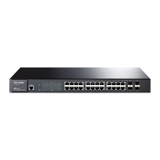
IP telephones, wireless LAN access points, network cameras, network hubs, embedded computers etc. 1.2 Appearance Front Panel ■ The front panel of TL-SG3210 is shown as the following figure. LEDs Console Port 10/100/1000Mbps RJ45 Port SFP Port Figure 1-1 Front Panel of TL-SG3210... - Page 6 L2 Managed Switch LEDs Status Indication The switch is powered on. The switch is powered off or power supply is abnormal. Flashing Power supply is abnormal. Flashing The switch works properly. On/Off The switch works improperly. A device is linked to the corresponding port. Flashing Data is being transmitted or received.
- Page 7 L2 Managed Switch Status Indication A 1000Mbps device is connected to the corresponding port. 1000Mbps A 10/100Mbps device or no device is connected to the corresponding port. A device is connected to the corresponding port, but no activity. Link/Act Flashing Data is being transmitted or received.
- Page 8 SFP transceiver slots that are shared with the associated RJ45 ports. The associated two ports are referred as a “Combo” port, which means they cannot be used simultaneously, otherwise only SFP port works. TL-SG3210 features two individual SFP ports.
- Page 9 L2 Managed Switch Grounding Terminal Power Socket Figure 1-5 Rear Panel of TL-SG3210 The rear panel of TL-SG3216/TL-SG3424/TL-SG3424P is shown as the following figure. Grounding Terminal Power Socket Figure 1-6 Rear Panel of TL-SG3216/TL-SG3424/TL-SG3424P Grounding Terminal The switch already comes with lightning protection mechanism. You can also ground the switch through the PE (Protecting Earth) cable of AC cord or with Ground Cable.
-
Page 10: Chapter 2 Installation
L2 Managed Switch Chapter 2 Installation 2.1 Package Contents Make sure that the package contains the following items. If any of the listed items is damaged or missing, please contact your distributor. One Switch One Power Cord, One Console This Installation Guide Cable and one Ground Cable One Resource CD Two mounting brackets and... - Page 11 L2 Managed Switch Please keep a proper temperature and humidity in the equipment room. Too high/low humidity may lead to bad insulation, electricity leakage, mechanical property changes and corrosions. Too high temperature may accelerate aging of the insulation materials and can thus significantly shorten the service life of the device. For normal temperature and humidity of the device, please check the following table.
-
Page 12: Installation Tools
L2 Managed Switch Ensure the rack and device are well earthed. ■ Make sure the power socket has a good contact with the ground. ■ Keep a reasonable cabling system and avoid induced lightning. ■ Use the signal SPD (Surge Protective Device) when wiring outdoor. ■... -
Page 13: Rack Installation
L2 Managed Switch Feet Bottom of the Device Notch Figure 2-1 Desktop Installation Rack Installation ■ To install the device in an EIA standard-sized, 19-inch rack, follow the instructions described below: 1. Check the grounding and stability of the rack. 2. -
Page 14: Chapter 3 Lightning Protection
L2 Managed Switch Chapter 3 Lightning Protection 3.1 Cabling Reasonably In the actual network environment, you may need cable outdoors and indoors, and the requirements for cabling outdoors and indoors are different. A reasonable cabling system can decrease the damage of induced lightning to devices. Note: It’s not recommended using Ethernet cables outdoors. - Page 15 L2 Managed Switch Requirements for the distance between Ethernet cable and other pipelines are shown ■ in the table. Ethernet Cable Other Pipelines Min Parallel Net Length Min Parallel-overlapping Net Height L (mm) H (mm) Down-conductor 1000 Service pipe Compressed air pipe Thermal pipe (not wrapped) 500 Thermal pipe (wrapped) Gas pipe...
-
Page 16: Connect To Ground
L2 Managed Switch 3.2 Connect to Ground Connecting the device to ground is to quickly release the lightning over-voltage and over-current of the device, which is also a necessary measure to protect the body from electric shock. In different environments, the device may be grounded differently. The following will instruct you to connect the device to the ground in two ways, connecting to the grounding bar or connecting to the ground via the power cord. -
Page 17: Equipotential Bonding
L2 Managed Switch Note: The figure is to illustrate the application and principle. The power cord you get from ■ the package and the socket in your situation will comply with the regulation in your country, so they may differ from the figure above. If you intend to connect the device to the ground via the PE (Protecting Earth) cable ■... -
Page 18: Use Lightning Arrester
L2 Managed Switch 3.4 Use Lightning Arrester Power lightning arrester and signal lightning arrester are used for lighting protection. Power lightning arrester is used for limiting the voltage surge due to a lightning. If an outdoor AC power cord should be directly connected to the device, please use a power lightning arrester. -
Page 19: Chapter 4 Connection
Interface) of the switch and configure its corresponding Speed and Duplex mode on Switching→Port→Port Config page. For 100M module, please select 100MFD while select 1000MFD for gigabit module. By default, the Speed and Duplex mode of SFP port is 1000MFD. TL-SG3210 supports 1000M SFP module connection only. Connection... -
Page 20: Console Port
L2 Managed Switch 4.3 Console Port CLI (Command Line Interface) enables you to manage the switch, thus you can load the CLI after connecting the PCs or Terminals to the console port on the switch via the provided cable. Connect the console port of the device with your computer by the console cable as the following figure shows. -
Page 21: Initialization
After the device is powered on, it begins the Power-On Self-Test. A series of tests run automatically to ensure the device functions properly. During this time, its LED indicators will respond as follows. For TL-SG3210 Switch: The Power LED indicator will light on all the time. ■... -
Page 22: Chapter 5 Configuration
L2 Managed Switch Chapter 5 Configuration 5.1 Configure the Switch via GUI 1. To access the GUI of the switch, open a web browser and type the default management address http://192.168.0.1 in the address field of the browser, then press the Enter key. Figure 5-1 Web Browser Note: To log on to the GUI of the switch, the IP address of your PC should be set in the same subnet addresses of the switch. -
Page 23: Configure The Switch Using Cli
L2 Managed Switch Figure 5-3 Main Page of the Switch 5.2 Configure the Switch Using CLI You can log on to the switch and access the CLI by the following two methods: Log on to the switch by the console port on the Switch. ■... - Page 24 L2 Managed Switch 3. The Connection Description Window will prompt as Figure 5-5. Enter a name into the Name field and click OK. Figure 5-5 Connection Description 4. Select the port to connect in Figure 5-6, and click OK. Figure 5-6 Select the port to connect 5.
- Page 25 6. Type the User name and Password in the Hyper Terminal window, the factory default value for both of them is admin. The DOS prompt” TP-LINK>” will appear after pressing the Enter button as Figure 5-8 shown. It indicates that you can use the CLI now.
- Page 26 L2 Managed Switch Figure 5-9 Open the Run window 3. Type cmd in the prompt Run window as Figure 5-10 and click OK. Figure 5-10 Run Window 4. Type telnet 192.168.0.1 in the command prompt shown as Figure 5-11, and press the Enter button.
- Page 27 L2 Managed Switch 5. Type the User name and Password (the factory default value for both of them is admin) and press the Enter button, then you can use the CLI now, which is shown as Figure 5-12. Figure 5-12 Log in the Switch For detailed CLI configuration instructions, please refer to the CLI Reference Guide on the resource CD.
-
Page 28: Appendix A Troubleshooting
L2 Managed Switch Appendix A Troubleshooting What could I do if I forgot the username and password of the switch? 1. Connect the console port of the PC to the console port of the switch and open hyper terminal. 2. Power off and restart the switch. When you are prompted that “Press CTRL-B to enter the bootUtil”... -
Page 29: Appendix B Hardware Specifications
1000Base-T: 4-pair UTP (≤100m) of Cat. 5, Cat. 5e, and Cat. 6 or above 1000Base-X: MMF or SMF SFP Module (Optional) LEDs TL-SG3210: PWR, SYS, 10/100/1000M,1000M TL-SG3216/TL-SG3424: Power, System, 1000Mbps, Link/Act TL-SG3424P: Power, System, Speed, Port Status LED, PoE, PoE Max Operating Temperature 0℃~40℃... -
Page 30: Appendix C Technical Support
L2 Managed Switch Appendix C Technical Support For more help, please go to: http://www.tp-link.com/en/support/faq ■ To download the latest Firmware, Driver, Utility and User Guide, go to: ■ http://www.tp-link.com/en/support/download For all other technical support, please contact us by using the following details: ■... - Page 31 *Except French Bank holidays Australia/New Zealand Tel: NZ 0800 87 5465 (Toll Free) AU 1300 87 5465 (Depending on 1300 policy.) E-mail: support.au@tp-link.com (Australia) support.nz@tp-link.com (New Zealand) Service time: 24hrs, 7 days a week Switzerland Tel: +41 (0) 848 800 998 (German Service) Fee: 4-8 Rp/min, depending on rate of different time.
- Page 32 Website: http://www.tp-link.com Tel: +86 755 26504400 E-mail: support@tp-link.com 7106504888 REV2.0.1...
Need help?
Do you have a question about the TL-SG3210 and is the answer not in the manual?
Questions and answers