Table of Contents
Advertisement
Quick Links
Advertisement
Chapters
Table of Contents

Related Manuals for Kärcher WATERCLEAN 600 CD


Summary of Contents for Kärcher WATERCLEAN 600 CD
- Page 1 Service Handbook Waterclean 600 CD, LP/MP, PI 1.024-... 5.905-521 08.2004...
- Page 2 FOREWORD WTC 600 LP / MP Foreword Good servicing and maintenance requires comprehensive, practical training and clearly organised documents. This is why we offer all servicing engineers regular basic training and further qualification courses for the whole product range. In addition, we compile service manuals for the main units which can be used as instructions to start with and as a reference work later on.
-
Page 3: Table Of Contents
WTC 600 LP / MP Contents General... 7 - 10 Introduction ... 7 Marking of Instructions ... 7 Intended Use ... 7 Safety Instructions ... 8 1.4.1 Quality of the Untreated Water ... 8 1.4.2 Chlorination of Drinking Water ... 8 1.4.3 Disposal of Chemicals ... - Page 4 CONTENTS Contents 3.2.5.2 Perform flocking test ... 26 3.2.5.3 Evaluate flocking test ... 26 Connecting the Equipment ... 27 3.3.1 Connections, Valves and Indicators ... 27 3.3.1.1 Pressure-increase Module ... 28 3.3.1.2 RO Module with Preliminary Filters ... 28 3.3.2 Electrical Connections ...
- Page 5 WTC 600 LP / MP Contents 4.4.3.2 Cleaning Solution for Alkaline Cleaning ... 51 4.4.4 Conserving ... 51 4.4.4.1 Draining and rinse the metering stations ... 51 4.4.4.2 Conserve RO systems ... 51 4.4.4.3 Draining the pre-filter ... 53 4.4.5 Removing the Preservation After Longer Operational Interruptions ...
- Page 6 WTC 600 LP / MP Service Handbook 08.2004...
-
Page 7: General
WTC 600 LP / MP General Introduction This service manual contains basic instructions and information which are to be observed upon set-up, operation and maintenance. Therefore, it is imperative that the service manual is read by the installer as well as by the responsible specialist staff prior to installation and starting of operation. -
Page 8: Safety Instructions
GENERAL Safety Instructionse 1.4.1 Quality of the Untreated Water Sufficient quality of the untreated water must be ensured! Faultless drinking water is achieved only when all filters of the equipment are maintained regularly. 1.4.2 Chlorination of Drinking Water When applying post chlorination, the limit values set by national laws must be main- tained. -
Page 9: Handling Electricity / Protection Class
WTC 600 LP / MP 1.4.4 Handling Electricity / Protection Class Be aware of dangerous electrical voltage! For work on components/assemblies which are marked with this symbol, protective measures are to be taken: - Switch off the power - Secure against restarting - Check and assess that no voltage is given. -
Page 10: Description
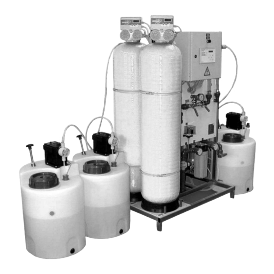
DESCRIPTION Description Overview Figure 1 Overview of components 4.12, 4.13 WTC 600 LP / MP 4.23 4.24 4.21 4.14 4.11 4.15 4.17 4.5, 4.6 Service Handbook 08.2004... - Page 11 WTC 600 LP / MP Legend for figure 1 and figure 2: 1.1 Pre-chlorination metering point 1.2 Manometer - media filter inlet pressure 1.3 Media filter 1.4 Differential pressure switch 1.5 Concussion restrictor 1.6 Flocculation metering point 2.1 Manometer - activated carbon filter inlet pressure 2.2 Activated carbon filter 4.1 Antiscalant metering point...
-
Page 12: Flow Diagram
DESCRIPTION Flow Diagram Figure 2 Flow diagram of the complete reverse osmosis system (RO system) WTC 600 LP / MP Service Handbook 08.2004... -
Page 13: Description Of The System
WTC 600 LP / MP Description of the System 2.3.1 Modular Design The installation is a drinking water conditioning system. Its core application is the emineralization of brackish water with a salt content up to 2000 ppm (WTC 600 LP), respectively up to 5000 ppm (WTC 600 MP). -
Page 14: Mediafilter- And Activated Carbon Filter
DESCRIPTION 2.3.1.3 Mediafilter- and Activated Carbon Filter The pre-filter units of the RO system consist of the media filter and the activated carbon filter. The filter fillings consist of support pebbles and filter sand according to DIN 19623, as well as activated carbon. -
Page 15: Pressure-Increase Pump
WTC 600 LP / MP 2.3.1.7 Pressure-increase Pump If required, the WTC 600 PI pressure-increase pump (6/1) is connected between untreated water supply and RO system. It is used for pressure increase of the untreated water. NOTE A pressure-increase pump should be used for a water pressure (flow pressure) 2 bar. -
Page 16: Operating Modes
DESCRIPTION Microfuses Two microfuses (7/6) for protection of the control electronics (7/5) are located on the control board for the electronics: - 5x20 6,3 A time-delay - 5x20 0,1 A time-delay. 2.3.3 Operating Modes 2.3.3.1 Automatic Operation (Standard Operating Mode) After switching on the main switch, the system is fully automatic controlled through the electronic control system and the float switch in the drinking water tank. -
Page 17: Technical Data Wtc 600 Lp/Mp
WTC 600 LP / MP Technical Data WTC 600 LP/MP Parameter Ambient temperature Storage temperature (delivery) Humidity Supply voltage Pre-filter controls: prim / sec. Metering pumps Wiring Electrical protection Connected electrical load Effective electrical power consumption Mechanical protection / protection against water Switch cabinet Pump and valves Metering pump... - Page 18 DESCRIPTION Filter Container Volume per container Filling capacities, Mediafilter Support pebbles 2.0 - 3.15 mm Filter sand 0.4 - 0.8 mm Filter amounts, activated carbon filter Support pebbles 1 - 2 mm Activated carbon filter F100 Water connections Inlet threaded connection hose nozzle Drinking water threaded connection hose nozzle Concentrate threaded connection hose nozzle Outlet for flushing water...
-
Page 19: Consumption Materials
WTC 600 LP / MP Consumption Materials Swear protective equipment and observe safety instructions! 2.5.1 Chemicals for Metering Container For mixing of the metering solution, use the measuring cup with the handle (250 ml or 1000 ml). Explanations of the units, see Chapter 1.6. NOTE NOTE A metering container from the WTC 600 CD metering station has a volume of 75 liter. -
Page 20: Operation Of The System
OPERATION OF THE SYSTEM Operation of the System Assembly and Starting Operation Assembly Checking the scope of delivery (delivery note) Placing the equipment in the set-up location and positioning Connecting the untreated water to the WTC 600 LP/MP; connecting the WTC 600 PI in between, if required (depending on delivery scope) Installing the piping for backwashing and drinking water Installing the float switch Filling and connecting the sand filter and the activated carbon filter... -
Page 21: Mixing Chlorine, Flocculation Agent And Antiscalant
WTC 600 LP / MP Mixing Chlorine, Flocculation Agent and Antiscalant 3.2.1 First fill of the metering tanks The first time they are filled, the metering tanks are filled with 30 litres of chlorine-free water. This is taking from the reverse osmosis at the drinking water sampling tap (1/12). For the first fill of the metering tank, the system is switched to disinfection mode and set to the following flow rates: - Drinking water: 100 l/h... - Page 22 OPERATION OF THE SYSTEM 5. For 75% yield: Total x 128 = _____ ml RM 852 per 10 litre metering solution Total x = _____ ml calcium hypochlorite (1ml corresponds to 1.05g) per 10 litres metering solution These values are entered in the customer's operating instructions. Calculation example: - Yield 75% - Iron (Fe) 1.0 mg/l...
-
Page 23: Antiscalant
WTC 600 LP / MP 3.2.3 Antiscalant The drinking water for the metering solution is taken from the sampling tap for drinking water (1/4.21). The antiscalant metering quantity can be set with a very good approximation using the following table. The optimum quantity can only be calculated using a calculation program after a precise water analysis has been carried out. -
Page 24: Metering Amounts And Mixing Of The Post Chlorination
OPERATION OF THE SYSTEM 3.2.4 Metering Amounts and Mixing of the Post Chlorination The chlorine quantity given matches a chlorine content of 0.3mg/l in the drinking water. The following quantities of RM 852 or calcium hypochlorite are each required for 10 litres of metering solution: - RM 852 Sterilization Agent: - Chlorinated Lime:... -
Page 25: Perform Flocking Test
WTC 600 LP / MP 3.2.5.2 Perform flocking test Auxiliaries: - Transparent cup, 1 litre with marking at 0.5 litre 6.277-001.0 - Dropping bottle with test solution 6.394-426.0 - Plastic eating spoon. Work Steps: 1. Measure pH-value of water, has to be between 6 and 9 2. -
Page 26: Connecting The Equipment
OPERATION OF THE SYSTEM Connecting the Equipment 3.3.1 Connections, Valves and Indicators Depending on the local untreated water supply, the WTC 600 LP/MP is connected directly to the off-site supply or supplemented through a WTC 600 PI pressure-increase module. The following constructional measures must be observed: - The off-site untreated water supply must be equipped with a shut-off device (supplied by user / customer). -
Page 27: Pressure-Increase Module
WTC 600 LP / MP 3.3.1.1 Pressure-increase Module Connection to the RO system (9/2) Hose shank d25 Connection to the untreated water (9/3) Hose shank d25 Observe mechanical protection of the electrical connection cable (9/1) as well CAUTION as protection against water! The fan wheel of the pump must be at least 20 cm away from the next wall. -
Page 28: Electrical Connections
OPERATION OF THE SYSTEM 3.3.2 Electrical Connections 3.3.2.1 Pressure-increase Pump 230 V external, via connection cable. 3.3.2.2 Preliminary Filter In delivery condition, the preliminary filters are connected to the power outlets (1/f) on the rear side of the RO equipment. 3.3.2.3 Metering Station The pumps of the projected metering stations are connected to the power outlets (1/g). - Page 29 WTC 600 LP / MP Metering Type Container Pre-chlorination Alarm output (12/1 Digital input (12/2) Antiscalant Alarm output (12/1) Digital input (12/2) Post chlorination Alarm output (12/1) Digital input (12/2) Table 13 Connection assignment: Empty message and releasing of the metering containers at the RO control CAUTION Electrically insulate cable ends that are not used with insulating terminals.
-
Page 30: Float Switch
OPERATION OF THE SYSTEM 3.3.2.4 Float Switch Connect the signal lines of the enclosed float switch to clamps 6/7 (8S3 option) of the connecting terminal – compare wiring diagram in the switching box. Upon installation, adjust a switching hysteresis of at least 300 liters between the switching-on and switching-off point. 3.3.2.5 Reverse Osmosis System The WTC 600 LP/MP is connected to the following power supply:... -
Page 31: Media Filter And Activated Carbon Filter
WTC 600 LP / MP 3.4.2 Media and Activated Carbon Filter 3.4.2.1 Initial Filling Remove the central control valve and position the central pipes with the lower nozzle in the middle of the tank floor. Fill the tank up to a third with water. Place the filling funnel (4.901-090.0) in the opening and fill the filter bed with a shovel (6.812-049.0) in accordance with Table 15: Filter Support pebbles... -
Page 32: Programming
OPERATION OF THE SYSTEM 3.4.2.4 Programming To start the programming, the covered pushbutton (15/1) to the left of the “TIME OF DAY” pushbutton (15/2) is to be pressed (a circular indentation can be felt under the front foil).The changing of the flashing positions is carried out with the “ADVANCE”... - Page 33 WTC 600 LP / MP Position Covered pushbutton Covered pushbutton Covered pushbutton Covered pushbutton Covered pushbutton TIME OF DAY Covered pushbutton Covered pushbutton Covered pushbutton Covered pushbutton Table 18 Programming table For changing of any given value from the programming table, the complete menu must be run through.
-
Page 34: Starting Operation Of The Ro System
OPERATION OF THE SYSTEM 3.4.3 Starting Operation of the RO System 3.4.3.1 Operating Levels and Passwords Normal Level: In this level, the operating mode, the operating condition as well as the current measuring and operating values are indicated on the display (5/2) with the help of changing (rotating) masks (see figure 16). -
Page 35: Selecting Several Arguments At The Same
WTC 600 LP / MP 3.4.3.4 Selecting Several Arguments at the Same For this a series of “0” (argument inactive) and “1” (argument active) appears on the bottom line of the display. With help of the between the individual characters. The activation / inactivation of an argument is carried out with pushbutton and the pushbutton respectively. - Page 36 OPERATION OF THE SYSTEM Indication: -Press the pushbutton. Indication: Press the RETURN pushbutton. Indication: -Press the pushbutton. Indication: Press the RETURN pushbutton. Indication: -Press the pushbutton. Indication: Press the RETURN pushbutton. Indication: Press the RETURN pushbutton. Indication: -Press the pushbutton. Indication: System in disinfection operating mode.
-
Page 37: Initial Startup
WTC 600 LP / MP 3.4.3.8 Initial startup - Set the equipment to the operation operating mode (see 3.4.4) - Set the drinking water capacity to 600 l/h - For very cold water, the drinking water capacity of 600 l/h is not achieved: Then adjust the maximum pump pressure of 21 bar (MP) or 14 bar (LP) - Adjust the concentrate capacity to 200 l/h (for very cold water possibly somewhat more) Closing the pressure control valve (11/1) - Page 38 OPERATION OF THE SYSTEM Checking the pressure control device (shut the untreated water supply for this): The RO system must switch off after a short time. THE “Fault” LED must light at the operating panel – Lack of pressure is indicated on the display (5/2).
-
Page 39: Normal Operation
WTC 600 LP / MP 3.4.4 Normal Operation Switch on the RO 1000 control; the following message appears on the display: The system has been switched off NOTE in the user or technician level. Switching on without password is not possible! When the following rotating masks appear: RO 1000 V 01.34 production on... -
Page 40: Operating Messages For Normal Operation
OPERATION OF THE SYSTEM Indication: The equipment produces and starts with rejection. Operating conditions: - „Production“ LED lights. - “Reject“ LED lights. After the reject period has run off, normal production with rotating indication: RO 1000 V 01.34 Production on When the RO equipment starts, the intake valve for untreated water is opened and the RO pump starts after the preset time and given pressure. -
Page 41: Putting Out Of Operation
WTC 600 LP / MP 3.4.5 Putting Out of Operation CAUTION Normally, do not switch off with the main switch (a possibly active flushing program may be interrupted). NOTE The RO system working in normal operation is switched off only via the float switch when the drinking water tank is full. -
Page 42: Disinfection
OPERATION OF THE SYSTEM 3.4.6 Desinfection Enter user password (compare with Chapter 3.4.3.1): Indication: Press the pushbutton one time. Indication: Press the RETURN pushbutton. Indication: Press the pushbutton. Indication: Press the RETURN pushbutton. Indication: Press the pushbutton. Indication: Press the RETURN pushbutton. Indication: Press the RETURN pushbutton. -
Page 43: Maintenance
WTC 600 LP / MP Maintenance Fine Filter The manometers (17/1 and 17/3) are located in front of and behind the fine filter unit (17/2). If the differential pressure is more than 0.8 bar, the fine filter is to be cleaned or replaced: - Stop the untreated water supply until the system is in the lack of pressure operating condition. -
Page 44: Reverse Osmosis Module (Ro Module)
MAINTENANCE Replacing the membrane - Set the pump lift adjustment knob (8/1) to 100 %. - Unscrew the 4 screws, size 6 mm, at the metering head and remove the metering head. - Unscrew the membrane to the left. - Reattach the sealing membrane1), intermediate ring and support disc again. - Screw in new membrane. -
Page 45: Cleaning In Case Of Malfunction
WTC 600 LP / MP - Apply Propandiol to the rubber seals. - Insert a new filter (19/7) at the supply opening (end without seal first!). - Attach all adapters. - Insert lid (19/4) in such a manner that the threads of the openings are flush with the nuts of the clamp (19/5). -
Page 46: Design Of The Flushing And Disinfection Equipment
MAINTENANCE 4.4.1 Design of the Flushing and Disinfection Equipment Figure 20 Diagram of connection principle for cleaning conserving and disinfection of the RO equipment Manometer Fine filter Solenoid valve 10. Check valve Pressure switch 11. Concentrate control valve RO Pump 12. - Page 47 WTC 600 LP / MP Work Steps: 1. Fill 30 liters of chorine-free drinking water into the flushing container (20/16). 2. Switch on master switch and set RO system to "Switched off" operating mode. 3. Close the untreated water inlet; depressurise system: - Use connection hoses and flushing pump (20/19) to connect the flushing tank with the untreated water sampling tap - Feed the drinking water adapter and connection hose from the drinking water outlet (20/8)
-
Page 48: Disinfection
MAINTENANCE 4.4.2 Disinfection A disinfection of the RO equipment becomes necessary when acidic and alkaline cleaning was not successful. NOTE The metering containers, supply lines, etc. should also be disinfected. Aids: - Per-acetic acid test stripes - Chemicals for disinfection and neutralization. Work Steps: 1. -
Page 49: Acidic And Alkaline Cleaning
WTC 600 LP / MP 4.4.3 Acidic and Alkaline Cleaning If the original drinking water capacity and quality can not be reached, an acidic cleaning or an alkaline cleaning of the equipment is to be carried out. Aids: - Universal indicator paper1) pH 0-14 - Chemicals for cleaning and for neutralization. -
Page 50: Cleaning Solution For Acidic Cleaning
MAINTENANCE 4.4.3.1 Cleaning Solution for Acidic Cleaning Volume of the cleaning solution [l] Table 23 Composition of the cleaning solution for acidic cleaning Neutralise by adding soda (6.287-014), until the pH value is approx. 7. 4.4.3.2 Cleaning Solution for Alkaline Cleaning Volume of the cleaning solution [l] Table 24... - Page 51 WTC 600 LP / MP Aids: - Conserving tank - Four connection hoses - Chemicals for conservation (compare with Table 25) and for neutralization - Conductive capacity measuring unit, for measurement comparison after flushing - Protective clothing (goggles, gloves, apron) - External pump.
-
Page 52: Draining The Pre-Filter
MAINTENANCE Preservation solution [l] Table 25 Chemicals for conserving solutions 4.4.4.3 Drain the pre-filter If the WTC 600 is shutdown for a lengthy period, the pre-filters have to be drained. this prevents bacterial growth and the filter material from caking as well as frost damage. Work steps: 1. - Page 53 WTC 600 LP / MP 4.4.6 Flushing the pre-filter The WTC 600 LP/MP pre-filter must be flushed if the differential pressure of the pre-filter immediately after back-washing is more than 0.5 bar. CAUTION Before flushing the filter, check the manometer for correct display values and exchange if necessary! CAUTION Pre-filter blockages are caused above all by changed water constituents.
- Page 54 MAINTENANCE System Volume of output [l/h] disinfectant solution [l] Table 26 Composition of the disinfectant solution 10. Flush the service kit with drinking water 11. Switch the RO system to run operating mode. 4.4.7 Replace the activated carbon or filter sand If the differential pressure at the pre-filters does not reduce despite flushing the filter medium (cf.
- Page 55 WTC 600 LP / MP MAINTENANCE Work steps: 1. Unscrew the controller from the control head and place to the side 2. Unscrew the untreated water, filtrate and back-washing pipes from the control head 3. Unscrew the control head from the pressure tank and pull of off the submersed pipe 4.
-
Page 56: Malfunction, Cause And Corrective Action
MAINTENANCE Malfunction, Cause and Corrective Action 4.5.1 Metering Station LED and Indicator LEDs at the Switch Cabinet Indication Malfunction Red fault LED Pump in metering lights station blocked regeneration LED lights Red tank full Float switch in the LED lights drinking water tank tank full has switched Table 27... -
Page 57: Malfunction Indication At The Operating Panel
WTC 600 LP / MP 4.5.2 Malfunction Indication at the Operating Panel The control system detects operational malfunctions only while in operation operating mode; these are indicated on the display. The occurrence of an error usually leads to the complete system being switched off (production is interrupted). -
Page 58: Malfunctions Of The Ro Control And Metering Pump
MAINTENANCE 4.5.3 Malfunctions of the RO Control and Metering Pump Indication Malfunction Indication of RO Fuse defective control dark Short circuit, general Solenoid valve defective Motor winding defective Water level in Pump does not container is draw in constant for days Pump does not meter... - Page 59 WTC 600 LP / MP 4.5.4 Malfunctions – Media and Activated Carbon Filter, Fine Filter and Flocculation Indication Malfunction More than one Backwashing is backwashing initiated too often per day (diagnosis controller) Backwashing no sufficient Sand conglutinated Differential Filtrate of the sand pressure of filter turbid fine filter quickly...
-
Page 60: Maintenance Plan
MAINTENANCE Maintenance Plan 4.6.1 Maintenance During Operation Module RO module: Flow meter RO module: Differential pressure RO control: Display Metering container Media filter/activated carbon filter Control sheet Metering stations Float switch, drinking water tank Metering stations Metering stations Fine filter RO module (when conserved) Tabelle 32 Cycle / Time... -
Page 61: Maintenance Plan Service
WTC 600 LP / MP 4.6.2 Maintenance Plan – Service NOTE Measured and read values are to be entered into the maintenance record. Module Media filter Activated carbon filter Fein filter Reverse osmosis Metering pump Table 33 Maintenance work to be carried out during service Other Maintenance When the RO equipment should not be used for more than 14 days, then it must be conserved. -
Page 62: Appendix
APPENDIX Appendix: RO control factory settings: WTC 600 LP, LP-A, LP-AM in voltages 230 V and 400 V Operating mode Switched off LF limits GWV: Alarm option Switch off Calibration Permeate temperature Permeate conductivity Settings t-GW delay: t-GWV delay t-pressure deficit t-Press. - Page 63 WTC 600 LP / MP WTC 600 MP, MP-A, MP-AM in voltages 230 V and 400 V Operating mode Switched off LF limits GWV: Alarm option Switch off Calibration Permeate temperature Permeate conductivity Settings t-GW delay: t-GWV delay t-pressure deficit t-Press.
-
Page 64: Ro Control Program Structure
APPENDIX WTC 600 LP / MP RO control program structure Figure 21 Service Handbook 08.2004... - Page 65 WTC 600 LP / MP APPENDIX Service Handbook 08.2004...
- Page 66 APPENDIX WTC 600 LP / MP RO 1000: Manual Control System RO 1000 MANUAL Service Handbook 08.2004...
- Page 67 WTC 600 LP / MP Contents General... 69 - 74 General remarks ... 69 Scope of Application ... 69 Instructions for Use ... 70 Safety Instructions ... 70 Terms and Definitions ... 71 Declaration of Conformity ... 71 Installation/Start-up ... 72 - 73 Basic Requirements ...
- Page 68 APPENDIX Contents Operating Levels ... 83 4.3.1 Normal Level ... 83 4.3.2 User Level ... 83 4.3.3 Technician's Level ... 83 Menu Structure ... 85 4.4.1 Main Menu ... 86 4.4.2 Calibration Menu ... 87 4.4.3 Setting Menu ... 88 4.4.4 Diagosis Menu ...
-
Page 69: General
WTC 600 LP / MP General General Remarks The present Manual is the technical documentation of the RO 1000 control system for reverse osmosis units. When studying this manual, it would be useful to have the control system ready for operation so that you can directly try to realize the explained items and functions. -
Page 70: Instructions For Use
APPENDIX Instructions for Use The following instructions should be followed when operating the control system: – Do not switch on/off the control system in quick succession. Wait at least 5 seconds between switching the main switch on and off. – The control system should only be operated under the ambient conditions (temperature, humidity) mentioned in the technical data (see item 5). -
Page 71: Terms And Definitions
WTC 600 LP / MP Terms and Definitions The following scripts will be used for this manual: Item Script keys capital letters + bold LED's capital letters + bold inlets/outlets capital letters + bold operating settings italics operating parameters italics operating modes capitals + underligned operating conditions... -
Page 72: Installation/Start-Up
APPENDIX Installation/Start-up Basic Requirements for System Installation The following remarks have to be observed during installation and connection of the RO 1000 unit: – The connected consumers must not exceed the max. admissible loads of the circuit outputs as well as the total output of the unit (see item 5) (in case of inductive loads, the phase angles have to be taken into account). -
Page 73: Function Of Terminals
WTC 600 LP / MP Function of Terminals Terminal arrangement and functions are as follows: Code Function Mains supply - protective. conduct Mains supply - neutral conductor Mains supply - phase ENT-PE softener - protective conductor ENT-N softener - neutral conductor ENT-L softener - phase P1-PE... -
Page 74: Operational Scope
APPENDIX Operational Scope Operating settings The control system allows to preselect the following operating settings (realization see item 4). The resulting control behaviours are described in the chapter Operating Conditions. The standard values (setting after parameter reset) are marked by * in the appropriate field. ps LIM high ps acknowledgment ps concentrate mode... -
Page 75: Operating Parameters
WTC 600 LP / MP Operating parameters The control system allows the following operating parameter settings (realization see item 4). The resulting behaviours are described in the chapter operating conditions. The values in brackets are the standard values after system reset (see item 4.4.4). aaLIM t-delay LIM t-delay aaLIM... - Page 76 APPENDIX t rinse interval t concentrate t min disposal t max disposal t maintenance function: Time after which a DISCONTINUOUS RINSE process is started provided that the control system was during that time in the operating condition RINSE INTERVAL. right of access: technician possible setting: 0-99h (0h) function: Duration of a CONCENTRATE...
-
Page 77: Operation
WTC 600 LP / MP APPENDIX Operating parameters When the control system is switched on, the following four operating modes exist: STOP The control system does not carry out any production process. All outputs remain inactive. Failures are not registered. OPERATION The control system fulfills the production in accordance with the respective operating conditions in the unit. -
Page 78: Operating Conditions
APPENDIX WTC 600 LP / MP Operating conditions When the unit is in OPERATION the control system performs one of the seven possible operating conditions. The following diagram shows the various conditions as well as the reasons for status changes. For that purpose an error-free sequence of operations is assumed. Service Handbook 08.2004... -
Page 79: Operating Failures/Failure Messages
WTC 600 LP / MP Operating failures/failure messages The control system is able to detect operating failures during OPERATION and DISINFECTION and to display them. Usually, the unit will be stopped if a failure occurs. However, operating settings exist for the failures CY EXCEEDED and HARDWATER which make it possible that such a failure is only displayed without interruption of the production. -
Page 80: Operation
APPENDIX Operation User interface The user interface of the RO 1000 consists of a text display (16x2 characters), a keyboard covered with a protective film (6 keys) and 7 indicator lights. 4.1.1 Indicator lights The indicator lights correspond to the most important operating conditions of the unit. The control system has the following indicator lights: OPERATION Active, if the control system is in the operating mode OPERATION and if at least one pump is... -
Page 81: Basic Elements
WTC 600 LP / MP Basic elements The whole user surface of the control system is composed by basis functions such as password entry, menu selection, selection of settings, numerical entries etc. The description of the basic functions will be followed by the operating elements of the menus for users/ techniciens. -
Page 82: Multiselection
APPENDIX 4.2.4 Multiselection The multiselection allows to select various arguments simultaneously (for the purpose of this paper, argument means any type of setting). In the lowest line of the text display appears for that purpose a chain of "0" and "1". Each one of these characters represents an argument. -
Page 83: Operating Levels
WTC 600 LP / MP Operating levels Similar to the operating modes, the user surface has different operating levels: Normal level: In this level, the text display shows the operating mode, the operating condition, the current measured values and operating values as well as special messages (maintenance message) by means of different (scrolling) masks (see 4.3.1). - Page 84 APPENDIX 4.3.2 User's Level Access to the user level is achieved by entering a user's password (see 4.2.1). This level allows operation and setting of the most important functions and operating settings/parameters respectively. The operating status is not displayed because display is used to represent the menus to do selections and editing.
-
Page 85: Menu Structure
WTC 600 LP / MP APPENDIX Menu structure The menu structure of the user surface is shown below. Access to the main menu is achieved by entering a pass word (see item 4.2.1). Service Handbook 08.2004... -
Page 86: Main Menu
APPENDIX 4.4.1 Main menu The details of the different menu points of the main menu are described below. Menu point: Function: 1 Ackn. failure This menu point allows to acknowledge an operating failure (the only possibility if ps acknowledgement = with password). 2 Operat. -
Page 87: Calibration Menu
WTC 600 LP / MP 4.4.2 Calibration menu The calibration menu is used to adjust the sensors. The following functions are available: Menu point: Function: 1 Cy permeate Calibration of permeate sensor. If the menu point '1 Cy permeate' is chosen, a submenu appears with two items: '1 min. -
Page 88: Setting Menu
APPENDIX 4.4.3 Setting menu The calibration menu is used to adjust the sensors. The following functions are available: Menu point: Function: 1 t Cy LIM Numerical editing of t delay LIM 2 t Cy alarm Numerical editing of t delay aaLIM 3 t lack of pressure Numerical editing of t delay lack of pressure 4 t delay at start... -
Page 89: Technical Data
WTC 600 LP / MP Technical Data The following table contains all significant technical data of the RO 1000 control. nominal service voltage main frequenCy nominal voltamps ambient temperature range (operation) ambient temperature range (storage) relative air humidity conductivity range - accuraCy of measurement (ref. - Page 90 APPENDIX WTC 600 LP / MP Service Handbook 08.2004...
-
Page 91: List Of Key Words
WTC 600 LP / MP Acidic and Alkaline Cleaning ... 49 Acknowledging Data Inputs ... 35 Activated Carbon Filter... 31 Activated carbon filter ... 11 Adjusting Operating Parameters and Balancing Value ... 35 Alphanumerical editing ... 82 Anti Scalant and Post Chlorination ... 14 Antiscalant ... - Page 92 LIST OF KEY WORDS Indicator lights ... 80 Initial Filling ... 31 Initial startup ... 37 Input solenoid valve ... 11 Installation/Start-up ... 72 Instructions for Use ... 70 Keyboard ... 80 Main menu ... 86 Maintenance ... 43 Maintenance During Operation ... 60 Maintenance Plan ...
- Page 93 WTC 600 LP / MP LIST OF KEY WORDS RC Protective Switch ... 15 Regeneration ... 31 Removing the Preservation After Longer Operational ... 52 Replace the activated carbon or filter sand ... 54 Reverse osmosis control ... 11 Reverse Osmosis Module (RO Module) ... 44 Reverse Osmosis System ...
Need help?
Do you have a question about the WATERCLEAN 600 CD and is the answer not in the manual?
Questions and answers