Korenix JetNet 6710G Series User Manual
Industrial 8-port poe + 2 gigabit tx managed ethernet switch
Hide thumbs
Also See for JetNet 6710G Series:
- User manual (173 pages) ,
- Quick installation manual (52 pages) ,
- Quick installation manual (11 pages)
Table of Contents
Advertisement
Quick Links
Download this manual
See also:
User Manual
Advertisement
Table of Contents

Related Manuals for Korenix JetNet 6710G Series


Summary of Contents for Korenix JetNet 6710G Series
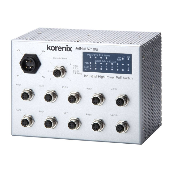
- Page 1 Korenix JetNet 6710G Series Industrial 8-Port PoE + 2 Gigabit TX Managed Ethernet Switch User Manual Ver. 05, Jun-2011 Firmware v1.0a www.korenix.com...
- Page 2 Korenix JetNet 6710G Series Industrial 8 Port PoE + 2 Gigabit TX Managed Ethernet Switch User’s Manual Copyright Notice Copyright © 2010 Korenix Technology Co., Ltd. All rights reserved. Reproduction in any form or by any means without permission is prohibited.
- Page 3 Federal Communications Commission (FCC) Statement This equipment has been tested and found to comply with the limits for a Class A digital device, pursuant to Part 15 of the FCC Rules. These limits are designed to provide reasonable protection against harmful interference when the equipment is operated in a commercial environment.
-
Page 4: Table Of Contents
Security....................... 106 4.11 Warning........................113 4.13 Monitor and Diag ....................124 4.14 Device Front Panel ..................... 132 4.15 Save to Flash...................... 133 4.16 Logout......................... 134 Appendix .......................... 135 Product Specifications..................135 Korenix Private MIB.................... 140 Revision History....................142 About Korenix ..................... 143... -
Page 5: Introduction
1 Introduction Welcome to Korenix JetNet 6710G Series Industrial 8-Port PoE + 2G Managed Ethernet Switch User Manual. Following topics are covered in this chapter: 1.1 Overview 1.2 Major Features 1.3 Package Checklist Overview The JetNet 6710G series are Managed Industrial Power over Ethernet Switches, equipped with 8 ports 10/100 TX with 15.4 watts PoE injector and 2... - Page 6 R.M. auto-selection mode. Seamless Ring Port Restoration Seamless restoration is a new Korenix patented technology which can restore a failed ring without causing any loop problem, topology change, packet loss and restoration time. This makes a perfect restoration that will not result in any...
- Page 7 Rapid Dual Homing (RDH ) Technology Rapid Dual Homing is also the important feature of Korenix new generation Ring technology. It supports ring coupling with other vendors and with easy configuration and multiple redundancies, the failover time is much faster and the restore time is zero ms.
-
Page 8: Major Features
8 –port IEE 802.3af 15.4w /802.3at 30w Power over Ethernet Auto Power Budget Control with Thermal Detection 32Gbps switch Fabric, 8K MAC address Korenix patented MSR pattern aggregates up to 4 x 100M Rings plus 1 Gigabit Ring LACP/VLAN/ GVRP/ QoS/ IGMP Snooping/Rate Control/ Online Multi-Port Mirroring/DHCP /IEEE 802.1AB LLDP... -
Page 9: Package List
Note: The detail spec is listed in Appendix 5.1. Package List Korenix JetNet 6710G Series products are shipped with following items that indicated in the table: JetNet 6710G Managed High Power IEEE 802.3at PoE Switch (M12 / Rugged RJ) JetNet 6810 Managed Booster PoE Switch ( M12 / Rugged RJ) -
Page 10: Hardware Installation
2 Hardware Installation This chapter includes hardware introduction, installation and configuration information. Following topics are covered in this chapter: 2.1 Hardware Introduction Dimension Panel Layout Bottom View 2.2 Wiring Power Inputs 2.3 RS-232 console and relay output 2.4 Wiring Earth ground 2.5 Wiring Ethernet Ports 2.6 Wall-mounting Installation... -
Page 11: Hardware Introduction
Hardware Introduction Dimension JetNet 6710G’s dimension (W x H x D) is 96mm x 137mm x 119mm JetNet 6710G-m12 JetNet 6710G-RJ... - Page 12 Panel Layout The front panel includes 10/100Mbps PoE ports, Gigabit Ethernet ports, RS232 console with DO port, System / Port LED and Power input.
-
Page 13: Wiring Power Inputs
Wiring Power Inputs The Power input port is located at the top of the front panel and supports redundant input function via a proprietary assembly capable IP-67 connector (CDG-L207SA) included in the shipment. If you cannot find this power connector, please contact your local distributor. For the available input power range and recommended cable size, please refer to the below table. - Page 14 Figure 2.2-2 Power connector assembly diagram...
-
Page 15: Wiring Rs-232 Console And Relay Output
Wiring RS-232 console and Relay Output The RS-232 console and the alarm relay are connected via the assembly type of 5-pole M12 A-coding connector included in the supplied package of JetNet switch. The following figure 3-2-1 is the disassembly diagram of M12 A-coding connector. -
Page 16: Wiring Earth Ground
Picture 9 – Console port pin assignment Step-3: Fasten the components 4, 5, 6 and 7 in sequence. Be sure the gasket is on the right position. See the below M12 assembly diagram: Picture 10 – M12 Assembly Wiring Earth Ground To ensure the system will not be damaged by noise or any electrical shock,... -
Page 17: Wiring Fast Ethernet Ports
we suggest you to make exact connection with JetNet 6710G with Earth Ground. On the left side of JetNet 6710G, there is one earth ground screw. Loosen the earth ground screw by screw driver; then tighten the screw after earth ground wire is connected. - Page 18 Assembly of M12 Ethernet Connector For Fast Ethernet M12 D-Code to M12 D-Code connection, you can use either version below: M12-M12 MDI -------------------------------------------------------------- RX+ -------------------------------------------------------------- TX+ -------------------------------------------------------------- RX- -------------------------------------------------------------- TX- M12-M12 MDI-X -------------------------------------------------------------- RX+ -------------------------------------------------------------- TX+ -------------------------------------------------------------- RX- -------------------------------------------------------------- TX- Picture 14 M12-to-M12 Ethernet Cable Wiring For Fast Ethernet M12 D-Code to RJ45 connection, the pin assignment of the patch cable is shown below:...
- Page 19 For Gigabit Ethernet M12 A-Code to RJ45 connection, the pin assignment of the patch cable is shown below, Picture 16 Gigabit M12-to-RJ45 Ethernet Cable Wiring...
- Page 20 Assembly of Rugged RJ45 Connector (JetNet 6710G-RJ/JetNet 6810G-RJ ) The RJ version provides robust connection by the field assembly capable rugged RJ45 connector. Each component of the connector is shown below: 3.3.2-1 Rugged RJ45 Connecter Components Follow the steps to assemble the rugged RJ45 connector: Picture 18 Rugged RJ45 Cable Connection diagram...
- Page 21 Following picture-19 shows the color code of Cat.-5E UTP/STP cable based on the two standards released by TIA/EIA – 568A and 568B. The 568B wiring is by far, the most common wiring method. You can choose the method that suits your application; but ensure that both ends of the cable use the same standard.
-
Page 22: Wall-Mounting Installation
Wall-Mounting Installation JetNet 6710G and JetNet 6810G series support wall-mounting only and there are 6 screw holes on the rear side of JetNet 6710G/JetNet 6810G for the mounting plate fixate; Use the screws included in the shipment to locking the plates as the figure-A and figure-B below. Note: To avoid damage the internal circuit, be sure use the screw included in the package to screw and tight the wall-mount kit onto the rear side of the JetNet switch. -
Page 23: Preparation For Management
3.3 Preparation for Telnet console Preparation for Serial Console In JetNet 6710G /JetNet 6810G package, Korenix attached one M12 to RS-232 DB-9 console cable. Please attach RS-232 DB-9 connector to your PC COM port, connects M12 to the Console port of the JetNet 6710G. -
Page 24: Preparation For Web Interface
HTTPS Web Interface for web management 3.2.1 Web Interface Korenix web management page is developed by JAVA. It allows you to use a standard web-browser such as Microsoft Internet Explorer, or Mozila, to configure and interrogate the switch from anywhere on the network. - Page 25 After logged out, you should re-login and key in correct user name and password again. 3.2.2 Secured Web Interface Korenix web management page also provides secured management HTTPS login. All the configuration commands will be secured and will be...
- Page 26 hard for the hackers to sniff the login password and configuration commands. Launch the web browser and Login. Launch the web browser (Internet Explorer or Mozila Firefox) on the Type https://192.168.10.1 (or the IP address of the switch). And then press Enter.
-
Page 27: Preparation For Telnet Console
2. Type the Telnet 192.168.10.1 (or the IP address of the switch). And then press Enter 3.3.2 SSH (Secure Shell) Korenix JetNet managed Switch also support SSH console. You can remotely connect to the switch by command line interface. The SSH connection can secure all the configuration commands you sent to the switch. - Page 28 2. After click on Open, then you can see the cipher information in the popup screen. Press Yes to accept the Security Alert.
- Page 29 3. After few seconds, the SSH connection to JetNet Switch is opened. You can see the login screen as the below figure- sample of JetNet 5010G. 4. Type the Login Name and its Password. The default Login Name and Password are admin / admin. All the commands you see in SSH are the same as the CLI commands you see via RS232 console.
-
Page 30: Feature Configuration
IP address. Then you can remotely connect to its embedded HTML web pages or Telnet console. Korenix web management page is developed by JAVA. It allows you to use a standard web-browser such as Microsoft Internet Explorer, or Mozila, to configure and interrogate the switch from anywhere on the network. -
Page 31: Command Line Interface Introduction
Command Line Interface Introduction The Command Line Interface (CLI) is the user interface to the switch’s embedded software system. You can view the system information, show the status, configure the switch and receive a response back from the system by keying in a command. There are some different command modes. - Page 32 Global Configuration Mode: Press configure terminal in privileged EXEC mode. You can then enter global configuration mode. In global configuration mode, you can configure all the features that the system provides you. Type interface IFNAME/VLAN to enter interface configuration mode, exit to leave.
- Page 33 (Port) Interface Configuration: Press interface IFNAME in global configuration mode. You can then enter interface configuration mode. In this mode, you can configure port settings. The port interface name for fast Ethernet port 1 is fa1,… fast Ethernet 7 is fa7, fast Ethernet port 8 is fa8..
- Page 34 Switch(config)# interface vlan 1 Switch(config-if)# description Interface specific description End current mode and change to enable mode exit Exit current mode and down to previous mode Interface Internet Protocol config commands list Print command list Negate a command or set its defaults quit Exit current mode and down to previous mode shutdown...
- Page 35 Type end to privileged EXEC mode. Enter: Type interface VLAN VLAN Interface In this mode, you can configure Switch(config-vlan)# VID in global configuration Configuration settings for specific VLAN. mode. Exit: Type exit or Ctrl+Z to global configuration mode. Type end to privileged EXEC mode.
- Page 36 Here are some useful commands for you to see these available commands. Save your time in typing and avoid typing error. ? To see all the available commands in this mode. It helps you to see the next command you can/should type as well. Switch(config)# interface (?) IFNAME Interface's name vlan...
-
Page 37: Basic Setting
Basic Setting The Basic Setting group provides you to configure switch information, IP address, User name/Password of the system. It also allows you to do firmware upgrade, backup and restore configuration, reload factory default, and reboot the system. Following commands are included in this group: 4.2.1 Switch Setting 4.2.2 Admin Password 4.2.3 IP Configuration... - Page 38 System Contact: You can specify contact people here. You can type the name, mail address or other information of the administrator. The available characters you can input are 64. System OID: The SNMP object ID of the switch. You can follow the path to find its private MIB in MIB browser.
- Page 39 Figure 4.2.2.2 Popup alert window for Incorrect Username. 4.2.3 IP Configuration This function allows users to configure the switch’s IP address settings. Below figure is the UI of IP configuraation. DHCP Client: You can select to Enable or Disable DHCP Client function. When DHCP Client function is enabled, an IP address will be assigned to the switch from the network’s DHCP server.
- Page 40 Note: In the CLI, we use the enabled bit of the subnet mask to represent the number displayed in web UI. For example, 8 stands for 255.0.0.0; 16 stands for 255.255.0.0; 24 stands for 255.255.255.0. Default Gateway: You can assign the gateway for the switch here. The default gateway is 192.168.10.254.
- Page 41 you change Time source to NTP Client. The system will send request packet to acquire current time from the NTP server you assigned. IEEE 1588: With the Precision Time Protocol IEEE 1588 there is now, for the first time, a standard available which makes it possible to synchronize the clocks of different end devices over a network at speeds faster than one Micro-second.
- Page 42 14 (GMT-05:00) Indiana (East) 15 (GMT-04:00) Atlantic Time (Canada) 16 (GMT-04:00) Caracas, La Paz 17 (GMT-04:00) Santiago 18 (GMT-03:00) NewFoundland 19 (GMT-03:00) Brasilia 20 (GMT-03:00) Buenos Aires, Georgetown 21 (GMT-03:00) Greenland 22 (GMT-02:00) Mid-Atlantic 23 (GMT-01:00) Azores 24 (GMT-01:00) Cape Verde Is. 25 (GMT) Casablanca, Monrovia 26 (GMT) Greenwich Mean Time: Dublin, Edinburgh, Lisbon, London 27 (GMT+01:00) Amsterdam, Berlin, Bern, Rome, Stockholm, Vienna...
- Page 43 63 (GMT+09:00) Yakutsk 64 (GMT+09:30) Adelaide 65 (GMT+09:30) Darwin 66 (GMT+10:00) Brisbane 67 (GMT+10:00) Canberra, Melbourne, Sydney 68 (GMT+10:00) Guam, Port Moresby 69 (GMT+10:00) Hobart 70 (GMT+10:00) Vladivostok 71 (GMT+11:00) Magadan, Solomon Is., New Caledonia 72 (GMT+12:00) Aukland, Wellington 73 (GMT+12:00) Fiji, Kamchatka, Marshall Is. 74 (GMT+13:00) Nuku'alofa Daylight Saving Time: Set the daylight saving time (summer time) start and end time.
- Page 44 Once you have finished the configuration, click Apply to apply your configuration Excluded Address: You can type a specific address into the IP Address field for the DHCP server reserved IP address. The IP address that is listed in the Excluded Address List Table will not be assigned to the network device.
- Page 45 DHCP Leased Entries: JetNet 6710G /JetNet 6810G provides an assigned IP address list for user check. It will show the MAC and IP address that was assigned by JetNet 6710G/JetNet 6810G. Click the Reload button to refresh the listing. DHCP Relay Agent You can select to Enable or Disable DHCP relay agent function, and then select the modification type of option 82 field.
- Page 46 (This is the default setting) Helper Address: there are 4 fields for the DHCP server’s IP address. You can filll the field with prefered IP address of DHCP Server, and then click “Apply” to activate the DHCP relay agent function. All the DHCP packets from client will be modified by the policy and forwarded to DHCP server through the gateway port.
- Page 47 Figure 4.2.6.1 Main UI of Backup & Restore Figure 4.2.6.2 Bacup/Restore Configuration - Local File mode Click on Folder icon to select the target file you want to backup/restore. Note that the folders of the path to the target file do not allow you to input space key.
- Page 48 Note: point to the wrong file will cause the entire configuration missed 4.2.7 Firmware Upgrade In this section, you can update the latest firmware for your switch. Korenix provides the latest firmware in Korenix Web site. The new firmware may include new features, bug fixes or other software changes.
- Page 49 existed configuration file to restore the configuration back to the switch. This mode is only provided by Web UI while CLI is not supported. TFTP Server mode: In this mode, the switch acts as the TFTP client. Before you do so, make sure that your TFTP server is ready. And then please type the IP address of TFTP Server IP address.
- Page 50 Type the IP address of TFTP Server and Firmware File Name. Then click on Upgrade to start the process. After finishing transmitting the firmware, the system will copy the firmware file and replace the firmware in the flash. The CLI show …… until the process is finished.
- Page 51 4.2.8 Factory Default In this section, you can reset all the configurations of the switch to default setting. Click on Reset the system will then reset all configurations to default setting. The system will show you popup message window after finishing this command.
- Page 52 when you use this command by CLI and Web UI, our software will not reset the IP address to default IP. The system will remain the IP address so that you can still connect the switch via the network. 4.2.9 System Reboot System Reboot allows you to reboot the device.
-
Page 53: Cli Commands For Basic Setting
MAC Address : 001277FF1533 Manufacturing Date : 2010/05/28 Software Information : Loader Version : 1.0.0.4 Firmware Version : 0.1.32-20100830-16:10:40 Copyright 2006-2009 Korenix Technology Co., Ltd.Switch# Switch# show hardware mac MAC Address : 00:12:77:FF:01:B0 Admin Password SWITCH(config)# administrator User Name and... - Page 54 SWITCH(config-if)# ip dhcp client renew Gateway SWITCH(config)# ip route 0.0.0.0/0 192.168.10.254/24 Remove Gateway SWITCH(config)# no ip route 0.0.0.0/0 192.168.10.254/24 SWITCH# show running-config Display ……… interface vlan1 ip address 192.168.10.8/24 no shutdown ip route 0.0.0.0/0 192.168.10.254/24 Time Setting SWITCH(config)# ntp peer NTP Server enable disable...
- Page 55 Switch(config-dhcp)#lease 300 (300 sec) Lease time configure Enable DHCP Relay Agent DHCP Relay Agent Switch# Switch# configure terminal Switch(config)# router dhcp Switch(config-dhcp)# service dhcp Switch(config-dhcp)# ip dhcp relay information option Enable DHCP Relay policy Switch(config-dhcp)# ip dhcp relay information policy replace drop Relay Policy keep...
- Page 56 ......................Firmware upgrade success!! Rebooting..Factory Default Switch# reload default-config file Factory Default Reload OK! Switch# reboot System Reboot Switch# reboot Reboot...
-
Page 57: Port Configuration
Port Configuration Port Configuration group enables you to enable/disable port state, or configure port auto-negotiation, speed, and duplex, flow control, rate limit control and port aggregation settings. It also allows you to view port status and aggregation information. Following commands are included in this group: 4.3.1 Port Control 4.3.2 Port Status 4.3.3 Rate Control... - Page 58 Fast Ethernet Port 1~8 (fa1~fa8) : AutoNegotiation, 10M Full Duplex(10 Full), 10M Half Duplex(10 Half), 100M Full Duplex(100 Full) and 100M Half Duplex(100 Half). Gigabit Ethernet Port 9~10: (gi9~gi10) : AutoNegotiation, 10M Full Duplex(10 Full), 10M Half Duplex(10 Half), 100M Full Duplex(100 Full), 100M Half Duplex(100 Half), 1000M Full Duplex(1000 Full), 1000M Half Duplex(1000 Half).
- Page 59 Speed/Duplex: Current working status of the port. Flow Control: The state of the flow control. 4.3.3 Rate Control Rate limiting is a form of flow control used to enforce a strict bandwidth limit at a port. You can program separate transmit (Egress Rule) and receive (Ingress Rule) rate limits at each port, and even apply the limit to certain packet types as described below.
- Page 60 IEEE standard, 802.3ad. The aggregated ports can interconnect to the other switch which also supports Port Trunking. Korenix Supports 2 types of port trunking. One is Static Trunk, the other is 802.3ad. When the other end uses 802.3ad LACP, you should assign 802.3ad LACP to the trunk. When the other end uses non-802.3ad, you can then use Static Trunk.
- Page 61 members. Since the member ports should use same speed/duplex, max trunk members for 100Mbps would be 8, and 2 for gigabit. Group ID: Group ID is the ID for the port trunking group. Ports with same group ID are in the same group. Type: Static and 802.3ad LACP.
-
Page 62: Command Lines For Port Configuration
4.3.5 Command Lines for Port Configuration Feature Command Line Port Control Switch(config-if)# shutdown -> Disable port state Port Control – State Port1 Link Change to DOWN interface fastethernet1 is shutdown now. Switch(config-if)# no shutdown -> Enable port state Port1 Link Change to DOWN Port1 Link Change to UP interface fastethernet1 is up now. - Page 63 Note: Administrative Status -> Port state of the port. Operating status -> Current status of the port. Duplex -> Duplex mode of the port. Speed -> Speed mode of the port. Flow control -> Flow Control status of the port. Rate Control Switch(config-if)# rate-limit Rate Control –...
- Page 64 Trunk Group GroupID Protocol Ports --------+---------+------------------------------------ Static 6(D) 7(P) Switch#...
-
Page 65: Power Over Ethernet
Power over Ethernet Power over Ethernet is one of the key features of JetNet 6710G series. It is fully IEEE802.3af-2003 compliant, and support IEEE802.3at, including 1-event with IEEE 802.1AB LLDP classificationfor PoE MDI. The JetNet 6710G adopts 8-Port PoE injectors in port 1 to port 8, each port with the ability to deliver 30W power. - Page 66 PoE System: pull down the PoE System to enable /disable PoE system and set the power budget of PoE system to prevent the loading is drawed over than the power supply output ability. After the setting, click “Apply” to enable those condifurations. Power Budget (w): the power supply output ability which is installed with PoE Switch.
- Page 67 IEEE 802.3at and Force modes. Power budget mode: the PoE port will not execute classification behavior and the power limit is refers to the each port’s power budget. Power Budget (w): the PoE output limitation of each PoE ports. This value and function only avaliabel at “power budget- manual “mode.
- Page 68 professional engineer. 4.4.2 PD Status Detection JetNet 6710G delivers a useful function – PD Status Detection. This provides automatic detection of a remote device powered by JetNet 5728G. If the remote system crashes or is unstable, JetNet 6710G will perform a system reboot by turning off and on again to trigger the remote device.
- Page 69 4.4.4 PoE Status The PoE Status page shows the operating status of each PoE Port. The information includes PoE mode, Operation status, PD class, Power Consumption, Voltage and Current. 4.4.5 Command Line for PoE control Syntax show poe system Parameters Command Mode Enable mode...
- Page 70 Description Display the status of the PoE system. Examples Switch> enable Switch# show poe system PoE System PoE Admin : Enable PoE Hardward : Normal PoE Input Voltage : 47.700 V Output power : 0.00 Watts Power Budget : Budget : 80 Watts Warning water level : N/A Utilization : 0 % Event : Normal...
- Page 71 Parameters IFNAME : interface name Command Mode Enable mode Description Display the status of schedule of interface. Examples Switch# show poe schedule fa1 Interface fastethernet1 POE Schedule Status : Disable Weekly Schedule : Sunday : 0,1,2,3,4,5,6,7,8,19,20,21,22,23 Monday : 0,1,2,3,4,5,6,7,8,19,20,21,22,23 Tuesday : 0,1,2,3,4,5,6,7,8,19,20,21,22,23 Wednesday : 0,1,2,3,4,5,6,7,8,19,20,21,22,23 Thursday : 0,1,2,3,4,5,6,7,8,19,20,21,22,23 Friday : 0,1,2,3,4,5,6,7,8,19,20,21,22,23...
- Page 72 Parameters enable: enable port in user mode disable: disable port in user mode Command Mode Interface mode Description Enable/Disable the PoE of the port in user mode. If in schedule mode, it will come into affect when the control mode changes to user mode. Examples To enable the PoE function in user mode Switch(config-if)# poe user enable...
- Page 73 Description Add a day schedule to an interface. Examples Add a schedule which enables PoE function at hour 1, 3, 5 and 10 to 23 on Sunday. Switch(config-if)# poe schedule 0 1,3,5,10-23 no poe schedule weekday Syntax Parameters Weekday : Valid range 0-6 (0=Sunday, 1=Monday, …, 6=Saturday) Command Mode Interface mode...
-
Page 74: Network Redundancy
Multiple Super Ring (MSR) technology is Korenix’s 3 generation Ring redundancy technology. This is patented and protected by Korenix and is used in countries all over the world. MSR ranks the fastest restore and failover time in the world, 0 ms for restore and about 5 milliseconds for failover for copper. - Page 75 Rapid Spanning Tree Protocol (RSTP) was adopted and represents the evolution of STP, providing much faster spanning tree convergence after a topology change. This is specified in IEEE 802.1w. In 2004, 802.1w is included into 802.1D-2004 version. This switch supports both RSTP and STP (all switches that support RSTP are also backward compatible with switches that support only STP).
- Page 76 Bridge Configuration Priority (0-61440): RSTP uses bridge ID to determine the root bridge, the bridge with the highest bridge ID becomes the root bridge. The bridge ID is composed of bridge priority and bridge MAC address. So that the bridge with the highest priority becomes the highest bridge ID.
- Page 77 bridge at the specified port. Priority: Enter a value between 0 and 240, using multiples of 16. This is the value that decides which port should be blocked by priority in a LAN. Admin P2P: Some of the rapid state transitions that are possible within RSTP depend upon whether the port of concern can only be connected to another bridge (i.e.
- Page 78 Typically, the managed switches are connected in series and the last switch is connected back to the first one. In such connection, you can implement Korenix Super Ring, Rapid Super Ring, and Multiple Super Ring technology. Super Ring is Korenix 1 generation ring redundancy technology released with JetNet 4000 and 4500 series managed switches.
- Page 79 This is Korenix pattern and protected in countries all over the world. The Multiple Super Ring has enhanced Ring Master selection and faster recovery time. It is also enhanced for more complex ring application. This page allows you to enable the settings for Multiple Super Ring and Rapid Dual Homing.
- Page 80 Path Cost: Change the Path Cost of Ring Port2 Rapid Dual Homing: Rapid Dual Homing is an important feature of Korenix 3 generation Ring redundancy technology. When you want to connect multiple RSR or form redundant topology with other vendors,RDH could allow you to have maximum 7 multiple links for redundancy without any problem.
- Page 81 4.5.4 Ring Info This page shows the RSR information. ID: Ring ID. Version: which version of this ring, this field could be Rapid Super Ring, Super Ring, or Any Ring Role: This Switch is RM or nonRM Status: If this field is Normal which means the redundancy is approved. If any one of the link in this Ring is broken, then the status will be Abnormal.
- Page 82 4.5.5 Command Lines: Feature Command Line RSTP Enable Switch(config)# spanning-tree enable Disable Switch (config)# spanning-tree disable RSTP mode Switch(config)# spanning-tree mode rapid-stp SpanningTree Mode change to be RST(802.1w) . STP mode Switch(config)# spanning-tree mode stp SpanningTree Mode change to be STP(802.1d) . Priority Switch(config)# spanning-tree priority <0-61440>...
- Page 83 Summary of connected spanning tree ports : #Port-State Summary Blocking Listening Learning Forwarding Disabled -------- --------- -------- ---------- -------- #Port Link-Type Summary AutoDetected PointToPoint SharedLink EdgePort ------------ ------------ ---------- -------- Port Info Switch# show spanning-tree port detail fa7 (Interface_ID) Rapid Spanning-Tree feature Enabled Port 128.6 as Disabled Role is in Disabled State Port Path Cost 200000, Port Identifier 128.6...
- Page 84 Switch(config-multiple-super-ring)# rapid-dual-homing disable Switch(config-multiple-super-ring)# rapid-dual-homing port IFLIST Interface name, ex: fastethernet1 or gi8 auto-detect up link auto detection IFNAME Interface name, ex: fastethernet1 or gi8 Switch(config-multiple-super-ring)# rapid-dual-homing port fa3,fa5-6 set Rapid Dual Homing port success. Note: auto-detect is recommended for dual Homing.. Ring Info Ring Info Switch# show multiple-super-ring [Ring ID]...
-
Page 85: Vlan
VLAN A Virtual LAN (VLAN) is a “logical” grouping of nodes for the purpose of limiting a broadcast domain to specific members of a group without physically grouping the members together. That means, VLAN allows you to isolate network traffic so that only members of VLAN could receive traffic from the same VLAN members. - Page 86 4.6.1 VLAN Port Configuration VLAN Port Configuration allows you to set up VLAN port parameters to specific port. These parameters include PVID, Accept Frame Type and Ingress Filtering. Figure 4.6.1-1 Web UI of VLAN configuration PVID: The abbreviation of the Port VLAN ID. Enter port VLAN ID here. PVID allows the switches to identify which port belongs to which VLAN.
- Page 87 example, if a tagged frame from Engineer VLAN is received, and Ingress Filtering is enabled, the switch will determine if the port is on the Engineer VLAN’s Egress list. If it is, the frame can be processed. If it’s not, the frame would be dropped.
- Page 88 Figure 4.6.2-2 The steps to create a new VLAN: Type in VLAN ID and NAME, and press Add to create a new VLAN. Then you can see the new VLAN in the Static VLAN Configuration table. Refer to Figure 4.6.2-3 After created the VLAN, the status of the VLAN will remain in Unused until you add ports to the VLAN.
- Page 89 Figure 4.6.2-4 Configure Egress rule of the ports. -- : Not available U: Untag: Indicates that egress/outgoing frames are not VLAN tagged. T : Tag: Indicates that egress/outgoing frames are to be VLAN tagged. Steps to configure Egress rules: Select the VLAN ID. Entry of the selected VLAN turns to light blue.
- Page 90 4.6.3 GVRP configuration GVRP allows users to set-up VLANs automatically rather than manual configuration on every port of every switch in the network. GVRP Protocol: Allow user to enable/disable GVRP globally. State: After enable GVRP globally, here still can enable/disable GVRP by port.
- Page 91 VLAN ID: ID of the VLAN. Name: Name of the VLAN. Status: Static shows this is a manually configured static VLAN. Unused means this VLAN is created by UI/CLI and has no member ports. This VLAN is not workable yet. Dynamic means this VLAN is learnt by GVRP. After created the VLAN, the status of this VLAN will remain in unused status until you add ports to the VLAN.
- Page 92 (for VLAN 2) switchport access vlan - success Egress rule – Tagged Switch(config-if)# switchport trunk allowed vlan add 2 (for VLAN 2) Display – Port Ingress Switch# show interface fa1 Rule (PVID, Ingress Interface fastethernet1 Filtering, Acceptable Administrative Status : Enable Frame Type) Operating Status : Not Connected Duplex : Auto...
- Page 93 VLAN description Switch(config)# interface vlan 2 Switch(config-if)# Switch(config-if)# description this is the VLAN 2 Switch(config-if)# no description ->Delete the description. IP address of the VLAN Switch(config)# interface vlan 2 Switch(config-if)# Switch(config-if)# ip address 192.168.10.18/24 Switch(config-if)# no ip address 192.168.10.8/24 ->Delete the IP address Create multiple VLANs Switch(config)# interface vlan 5-10...
-
Page 95: Traffic Prioritization
Traffic Prioritization Quality of Service (QoS) provides traffic prioritization mechanism which allows users to deliver better service to certain flows. QoS can also help to alleviate congestion problems and ensure high-priority traffic is delivered first. This section allows you to configure Traffic Prioritization settings for each port with regard to setting priorities. - Page 96 In JetNet, users can freely assign the mapping table or follow the suggestion of the 802.1p standard. Korenix uses 802.p suggestion as default values. You can find CoS values 1 and 2 are mapped to physical Queue 0, the lowest queue.
- Page 97 After configuration, press Apply to enable the settings. 4.7.3 DSCP-Queue Mapping This page is to change DSCP values to Physical Queue mapping table. Since the switch fabric of JetNet only supports 4 physical queues, Lowest, Low, Middle and High. Users should therefore assign how to map DSCP value to the level of the physical queue.
-
Page 98: Cli Commands Of The Traffic Prioritization
4.7.4 CLI Commands of the Traffic Prioritization Command Lines of the Traffic Prioritization configuration Feature Command Line QoS Setting Queue Scheduling – Switch(config)# qos queue-sched Strict Priority Strict Priority wrr Weighted Round Robin (Use an 8,4,2,1 weight) Switch(config)# qos queue-sched sp <cr>... - Page 99 -----+---- CoS-Queue Mapping Format Switch(config)# qos cos-map PRIORITY Assign an priority (7 highest) Switch(config)# qos cos-map 1 QUEUE Assign an queue (0-3) Note: Format: qos cos-map priority_value queue_value Map CoS 0 to Queue 1 Switch(config)# qos cos-map 0 1 The CoS to queue mapping is set ok. Map CoS 1 to Queue 0 Switch(config)# qos cos-map 1 0 The CoS to queue mapping is set ok.
- Page 100 Display – DSCO-Queue Switch# show qos dscp-map mapping DSCP to Queue Mapping : (dscp = d1 d2) d2| 0 1 2 3 4 5 6 7 8 9 -----+---------------------- 0 | 1 1 1 1 1 1 1 1 0 0 1 | 0 0 0 0 0 0 0 0 0 0 2 | 0 0 0 0 1 1 1 1 1 1 3 | 1 1 2 2 2 2 2 2 2 2...
-
Page 101: Multicast Filtering
Multicast Filtering For multicast filtering, JetNet 6710G uses IGMP Snooping technology. IGMP (Internet Group Management Protocol) is an Internet Protocol that provides a way for internet device to report its multicast group membership to adjacent routers. Multicasting allows one computer on the internet to send data to a multitude of other computers that have identified themselves as being interested in receiving the originating computers data. - Page 102 4.8.1 IGMP Snooping This page is to enable IGMP Snooping feature, assign IGMP Snooping for specific VLAN, and view IGMP Snooping table from dynamic learnt or static manual key-in. JetNet 6710G support IGMP snooping V1/V2/V3 automatically and IGMP query V1/V2. IGMP Snooping, you can select Enable or Disable here.
- Page 103 4.8.2 IGMP Query This page allows users to configure IGMP Query feature. Since JetNet 6710G can only be configured by member ports of the management VLAN, IGMP Query can only be enabled on the management VLAN. If you want to run IGMP Snooping feature in several VLANs, you should notice that whether each VLAN has its own IGMP Querier first.
- Page 104 4.8.3 Force Filtering The Force filtering function allows the switch to filter the unknown-multicast data flow. If Force filtering is enabled, all the unknown multicast data will be discarded. 4.8.4 CLI Commands of the Multicast Filtering Command Lines of the multicast filtering configuration Feature Command Line IGMP Snooping...
- Page 105 IGMP Query V2 Switch(config)# int vlan 1 (Go to management VLAN) Switch(config-if)# ip igmp IGMP Query version Switch(config-if)# ip igmp version 1 Switch(config-if)# ip igmp version 2 Disable Switch(config)# int vlan 1 Switch(config-if)# no ip igmp Display Switch# sh ip igmp interface vlan1 enabled: Yes version: IGMPv2...
-
Page 106: Snmp
SNMP Simple Network Management Protocol (SNMP) is a protocol used for exchanging management information between network devices. SNMP is a member of the TCP/IP protocol suite. JetNet 6710G series support SNMP v1 and v2c and An SNMP managed network consists of two main components: agents and a manager. - Page 107 4.9.2 SNMP V3 Profile SNMP v3 can provide more security functions when the user performs remote management through SNMP protocol. It delivers SNMP information to the administrator with user authentication; all of data between JetNet 6710G and the administrator are encrypted to ensure secure communication.
- Page 108 IP, Community name, and trap Version V1 or V2. After configuration, you can see the change of the SNMP pre-defined standard traps and Korenix pre-defined traps. The pre-defined traps can be found in Korenix private MIB, that included in the CD-manual or download from...
- Page 109 4.9.4 CLI Commands of the SNMP Command Lines of the SNMP configuration Feature Command Line SNMP Community Read Only Community Switch(config)# snmp-server community public ro community string add ok Read Write Community Switch(config)# snmp-server community private rw community string add ok SNMP Trap Enable Trap Switch(config)# snmp-server enable trap...
-
Page 110: Security
4.10 Security JetNet 6710G provides several security features for you to secure your connection. The features include Port Security and IP Security. Following commands are included in this group: 4.10.1 Port Security 4.10.2 IP Security 4.10.3 IEEE 802.1x 4.10.4 CLI Commands of the Security 4.10.1 Port Security Port Security feature allows you to stop the MAC address learning for specific port. - Page 111 Once you finish configuring the settings, click on Apply / Add to apply your configuration. 4.10.2 IP Security In IP Security section, you can set up specific IP addresses to grant authorization for management access to this JetNet via a web browser or Telnet.
- Page 112 4.10.3 IEEE 802.1x 4.10.3.1 802.1X configuration IEEE 802.1X is the protocol that performing authentication to obtain access to IEEE 802 LANs. It is port-base network access control. With the function, JetNet 6710G could control which connection is available or not. System AuthControl: To enable or disable the 802.1x authentication.
- Page 113 4.10.3.2 802.1x Port Configuration After the configuration of Radius Server or Local user list, user also need configure the authentication mode, authentication behavior, applied VLAN for each port and permitted communication. The following information will explain the port configuration. Port control: Force Authorized means this port is authorized; the data is free to in/out.
- Page 114 Control Direction: determined devices can end data out only or both send and receive. Re-Auth Period: control the Re-authentication time interval, 1~65535 is available. Quiet Period: When authentication failed, Switch will wait for a period and try to communicate with radius server again. Tx period: the time interval of authentication request.
- Page 115 4.10.4 CLI Commands of the Security Command Lines of the Security configuration Feature Command Line Port Security Add MAC Switch(config)# mac-address-table static 0012.7701.0101 vlan 1 interface fa1 mac-address-table unicast static set ok! Port Security Switch(config)# interface fa1 Switch(config-if)# switchport port-security Disables new MAC addresses learning and aging activities! Note: Rule: Add the static MAC, VLAN and Port binding first, then enable the port security to stop new MAC learning.
- Page 116 RADIUS Accounting Port number NOT given. (default=1813) Secondary RADIUS Server IP : 192.168.10.250 Secondary RADIUS Server Key : 5678 Secondary RADIUS Server Port : 1812 Secondary RADIUS Accounting Port : 1813 User name/password Switch(config)# dot1x username korenix passwd korenix vlan for authentication...
-
Page 117: Warning
4.11 Warning JetNet 6710G provides several types of Warning features for you to remote monitor the status of end devices or the change of your network. The features include Fault Relay, System Log and SMTP E-mail Alert. Following commands are included in this group: 4.11.1 Fault Relay 4.11.2 Event Selection 4.11.3 Syslog Configuration... - Page 118 How to configure: Type turn-on period and turn-off period when the time is reached, the system will turn on or off the Relay Output. If you connect DO to DI of the other terminal unit, the setting can help you to change DI state. If you connect DO to the power set of other terminal units, this setting can help you to turn on or off the unit.
- Page 119 Event Type: Ping Failure IP Address: IP address of the target device you want to ping. Reset Time (Sec): Waiting time to short the relay output. Hold Time (Sec): Waiting time to ping the target device for the duration of remote device boot How to configure: After selecting Ping Failure event type, the system will turn Relay Output to short state and continuously ping the target device.
- Page 120 Once you finish configuring the settings, click on Apply to apply your configuration.
- Page 121 4.11.2 Event Selection Event Types can be divided into two basic groups: System Events and Port Events. System Events are related to the overall function of the switch, whereas Port Events related to the activity of specific ports System Event Warning Event is sent when…..
- Page 122 Once you finish configuring the settings, click on Apply to apply your configuration 4.11.3 SysLog Configuration System Log is useful to provide system administrator locally or remotely monitor switch events history. There are 2 System Log modes provided by JetNet 6710G, local mode and remote mode. Local Mode: In this mode, JetNet 6710G will print the occurred events selected in the Event Selection page to System Log table of JetNet 6710G.
- Page 123 Once you finish configuring the settings, click on Apply to apply your configuration. Note: When enabling Local or Both modes, you can monitor the system logs in [Monitor and Diag] / [Event Log] page. 4.11.4 SMTP Configuration JetNet 6710G supports E-mail Warning feature. The switch will send the occurred events to remote E-mail server.
- Page 124 Field Description SMTP Server IP Address Enter the IP address of the email Server Authentication Click on check box to enable password User Name Enter email Account name (Max.40 characters) Password Enter the password of the email account Confirm Password Re-type the password of the email account You can set up to 4 email addresses to receive email alarm from JetNet Rcpt E-mail Address 1...
-
Page 125: Cli Commands
4.11.5 CLI Commands Command Lines of the Warning configuration Feature Command Line Relay Output Relay Output Switch(config)# relay 1 DI state dry output ping ping failure port port link failure power power failure ring super ring failure Note: Select Relay 1 or 2 first, then select the event types. DI State Switch(config)# relay 1 di <1-2>... - Page 126 Switch(config)# smtp-server server 192.168.10.100 admin@korenix.com SMTP Email Alert set Server: 192.168.10.100, Account: admin@korenix.com ok. Receiver mail Switch(config)# smtp-server receipt 1 korecare@korenix.com SMTP Email Alert set receipt 1: korecare@korenix.com ok. Authentication with Switch(config)# smtp-server authentication username admin username and password admin password...
- Page 127 SMTP Email Alert set Authentication disable ok. Dispaly Switch# sh smtp-server SMTP Email Alert is Enabled Server: 192.168.10.100, Account: admin@korenix.com Authentication: Enabled Username: admin, Password: admin SMTP Email Alert Receipt: Receipt 1: korecare@korenix.com Receipt 2: Receipt 3: Receipt 4:...
-
Page 128: Monitor And Diag
4.13 Monitor and Diag JetNet 6710G provides several types of features for you to monitor the status of the switch or diagnostic for you to check the problem when encountering problems related to the switch. The features include MAC Address Table, Port Statistics, Port Mirror, Event Log and Ping. Following commands are included in this group: 4.13.1 MAC Address Table 4.13.2 Port Statistics... - Page 129 address will be updated to MAC address table. 4.13.2 Port Statistics In this page, you can view operation statistics for each port. The statistics that can be viewed include Link Type, Link State, Rx Good, Rx Bad, Rx Abort, Tx Good, Tx Bad and Collision. Rx means the received packet while Tx means the transmitted packets.
- Page 130 4.13.3 Port Mirroring Port mirroring (also called port spanning) is a tool that allows you to mirror the traffic from one or more ports onto another port, without disrupting the flow of traffic on the original port. Any traffic that goes into or out of the Source Port(s) will be duplicated at the Destination Port.
- Page 131 4.13.4 Event Log In the 4.11.3, we have introduced System Log feature. When System Log Local mode is selected, JetNet 6710G will record occurred events in local log table. This page shows this log table. The entry includes the index, occurred data and time and content of the events.
- Page 132 4.13.5 Topology Discovery JetNet 6710G supports topology discovery or LLDP (IEEE 802.1AB Link Layer Discovery Protocol) function that can help user to discovery multi-vendor’s network devicec on same segment by NMS system which supports LLDP function; With LLDP function, NMS can easier maintain the topology map, display port ID, port description, system description, VLAN ID…...
-
Page 133: Cli Commands Of The Monitor And Diag
4.13.7 CLI Commands of the Monitor and Diag Command Lines of the Monitor and Diag configuration Feature Command Line MAC Address Table Ageing Time Switch(config)# mac-address-table aging-time 350 mac-address-table aging-time set ok! Note: 350 is the new ageing timeout value. Add Static Unicast MAC Switch(config)# mac-address-table static 0012.7701.0101 address... - Page 134 0012.7701.0386 Dynamic 0012.7710.0101 Static 0012.7710.0102 Static 0012.77ff.0100 Management ***** MULTICAST MAC ADDRESS ***** Vlan Mac Address Status Ports ---- --------------- ---- ------- -------------------------- 0100.5e40.0800 0100.5e7f.fffa fa4,fa6 Show MAC Address Switch# show mac-address-table dynamic Table – Dynamic Learnt Destination Address Address Type Vlan Destination Port MAC addresses...
- Page 135 Note: Select source port list and TX/RX/Both mode. Select Destination Port Switch(config)# mirror destination fa6 both Mirror destination fa6 both set ok Display Switch# show mirror Mirror Status : Enabled Ingress Monitor Destination Port : fa6 Egress Monitor Destination Port : fa6 Ingress Source Ports :fa1,fa2, Egress Source Ports :fa1,fa2, Event Log...
-
Page 136: Device Front Panel
4.14 Device Front Panel Device Front Panel command allows you to see LED status of the switch. You can see LED and link status of the Power, DO, R.M. and Ports. Feature LED On LED Blinking LED off Power Power is on applying Not avaliable No power System ready... -
Page 137: Save To Flash
4.15 Save to Flash Save Configuration allows you to save any configuration you just made to the Flash. Powering off the switch without clicking on Save Configuration will cause loss of new settings. After selecting Save Configuration, click on Save to Flash to save your new configuration. -
Page 138: Logout
4.16 Logout The switch provides 2 logout methods. The web connection will be logged out if you don’t input any command after 30 seconds. The Logout command allows you to manually logout the web connection. Click on Yes to logout, No to go back the configuration page. Command Lines: Feature Command Line... -
Page 139: Appendix
5 Appendix Product Specifications Technology Standard IEEE 802.3 10 Base-T Ethernet IEEE 802.3u 100 Base-TX Fast Ethernet IEEE 802.3ab 1000 Base-TX IEEE 802.3x Flow Control and Back-pressure IEEE 802.3af Power over Ethernet IEEE 802.3at Power over Ethernet Plus (LLDP PoE) IEEE 802.1AB Link Layer Discovery Protocol (LLDP) IEEE 802.1p Class of Service (CoS) IEEE 802.1Q VLAN and GVRP... - Page 140 IP address. SNMP MIB MIBII, Bridge MIB, Ethernet-like MIB, VLAN MIB, IGMP MIB, Korenix Private MIB. Korenix Utility Supports JetView and JetView Pro with IEEE 802.1AB Link Layer Discovery Protocol for device finding and link...
- Page 141 Network Redundancy Multiple Super Ring New generation Korenix Ring Redundancy Technology, (MSR) Includes Rapid Super Ring, Rapid Dual Homing, TrunkRing , MultiRing...
- Page 142 to 4 100M rings and 1 Gigabit ring in single switch. Rapid Spanning IEEE802.1D-2004 Rapid Spanning Tree Protocol. Tree Compatible with Legacy Spanning Tree and IEEE 802.1w. Interface Enclosure Port 10/100 Base-TX port JetNet 6710G-RJ: 8 x rugged RJ-45 JetNet 6710G-M12: 8 x M12-D-Code 4-pin Female 1000 Base-T port JetNet 6710G-RJ: 2 x rugged IP-67 RJ-45 JetNet 6710G-M12: 2 x M12-A-Code 8-pin Female...
- Page 143 Mechanical Installation Wall Mount Case Steel metal. Dimension (mm) JetNet 6710G-m12/ 6710G-RJ : 198 (W) x 145.2 (H) x 74 (D) w/o mounting kit JetNet 6710G-m12/ 6710G-RJ : 230.6 (W) x 145.2 (H) x 74 (D) w/mounting kit Weight JetNet 6710G-m12:1.92Kg JetNet 6710G-RJ:1.855Kg Environmental Operating...
-
Page 144: Korenix Private Mib
Korenix provides many standard MIBs for users to configure or monitor the switch’s configuration by SNMP. But, since some commands can’t be found in standard MIB, Korenix provides Private MIB to meet up the need. Compile the private MIB file by your SNMP tool. You can then use it. Private Private MIB tree is the same as the web tree. - Page 145 Basic Setting MIB entry: read and write Port Configuration MIB entry: Read and Write PoE MIB entry: Read and Write Network redundancy MIB entry: Read and Write Vlan MIB entry: Read and Write Traffic prioritization MIB entry: Read and Write Multicast Filtering MIB entry: Read and Write SNMP MIB entry: Read and write Security MIB entry: Read and write...
-
Page 146: Revision History
Revision History Edition Date Modifications New Edittion 11-Nov,2010 Modify M12 A 5-Pin connector pin assignment for console port. – Picture change Change Port Link LED description.- Specification 25-Nov,2010 Change Port –PoE output polarity information. – Specification Change VLAN group from 64 to 256. Modify drawing of Web UI Change RS description 15-DEC-2010... -
Page 147: About Korenix
Less Time At Work! Fewer Budget on applications! The Korenix business idea is to let you spend less time at work and fewer budget on your applications. Do you really want to go through all the troubles but still end up with low quality products and lousy services? Definitely not! This is why you need Korenix.
Need help?
Do you have a question about the JetNet 6710G Series and is the answer not in the manual?
Questions and answers