
Related Manuals for Korenix JetNet 3008f


Summary of Contents for Korenix JetNet 3008f
- Page 1 JetNet 3008 Series Industrial 8-port Ethernet Switch User’s Manual Version: 1.1 Date: 16-Sep, 2008...
-
Page 2: Table Of Contents
Content 1. Introduction .............1 1-1. Features ............1 1-2. Packing List............2 2. Hardware Description ........3 2-1. Dimensions ............3 2-2. Front Panel ............3 2-3. Bottom View ............4 2-4. LED Indicators ..........5 2-5. Ports..............6 3. Mounting Installation........7 DIN-Rail Mounting ............ - Page 3 Federal Communications Commission (FCC) Statement This equipment has been tested and found to comply with the limits for a Class A digital device, pursuant to Part 15 of the FCC Rules. These limits are designed to provide reasonable protection against harmful interference when the equipment is operated in a commercial environment.
-
Page 4: Introduction
To avoid interference as well as to extend your network coverage, JetNet 3008f is adapted to 2 100Mbps fiber ports with multi-mode 2KM or single-mode 30KM transceiver in order to achieve stable far-end transmissions. -
Page 5: Packing List
Dual power input DC12~48V Compliance with IEEE Hi-Pot Testing 1-2. Packing List JetNet 3008/JetNet 3008f Industrial 8-port Fast Ethernet Switch is packaged with the following items: JetNet 3008 or JetNet 3008f User’s manual CD-ROM Quick Installation Guide CD User’s Manual... -
Page 6: Hardware Description
2-4. LEDs of system and port 2-5. Connectors 2-1. Dimensions JetNet 3008 / JetNet 3008f 8-port Industrial Fast Ethernet Rail Switch dimensions are 120 mm (H) x 55 mm (W) x 108 mm (D), detail mechanical design drawings are attached as following: 2-2. -
Page 7: Bottom View
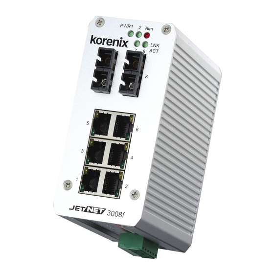
Figure A. Front Panel of the JetNet 3008 / JetNet 3008f. 2-3. Bottom View The bottom view of the JetNet 3008/JetNet 3008f Industrial 8-port Ethernet Switch consists of one 6-pin removable terminal block connector for two DC power inputs and event alarm output. There is one 9-pin DIP SWITCH on the bottom for alarm control of port or power event selection. -
Page 8: Led Indicators
2-4. LED Indicators There are some system diagnostic LEDs and Ethernet Port LEDs located on the front panel of JetNet3008 / JetNet 3008f Industrial 8-port Ethernet Switch. These LED indicators provide administrators with real-time system status. The table-1 gives the descriptions of the function of each LED indicator. -
Page 9: Ports
RJ-45 ports (Auto MDI/MDIX): JetNet 3008 has eight 10/100 Mbps auto-sensing RJ-45 ports for 10Base-T or 100Base-TX device connection and JetNet 3008f has six 10/100Mbps RJ-45 ports and two 100Mbps fiber ports for multi-mode or single-mode fiber cable in SC type connector. The RJ-45 ports will auto-detect 10Base-T and 100Base-TX connections. -
Page 10: Mounting Installation
DIN-Rail Mounting The DIN-Rail clip is already attached on the rear side of JetNet 3008/ JetNet 3008f. JetNet 3008 series supports EN 50022 standard DIN Rail, in the following diagram includes the dimension of EN 55022 DIN Rail for your reference. -
Page 11: Hardware Installation
Factory communication, field site communication and field site control layers. The control equipments access and report production information through the JetNet 3008 or JetNet 3008f and uplink to factory communication level by fiber or copper which with network redundancy. This session will introduce the hardware installation, includes: 4-1. -
Page 12: Wiring The Dc Power Inputs
4-1. Wiring the DC Power Inputs Follow the steps below to wire JetNet 3008’s / JetNet 3008f’s dual DC power inputs. [Note] The suitable electric wire ranges is from 12 to 24 AWG. V- V+ V- V+ 1. Insert the positive and negative wires into the V+ and V- contacts respectively of the terminal block connector 2. -
Page 13: Wiring The Alarm Relay
4-2. Wiring the Alarm Relay JetNet 3008 /JetNet 3008f provides one dry relay output for power or port link event; the alarm relay is “Normal open” and form a close circuit when The relay conductor ability is 24W when it connects with a DC 24V power source and maximum current is 1A. -
Page 14: Enabled The Event Alarm Function
This session introduces how to configure and enable the event alarm to alert maintenance engineer once system event occurred. Both of JetNet 3008 and JetNet 3008f equipped with one dry relay output for port link fails or power fails. The feature is controlled by digital control circuits and effect immediately without system reset when DIP SWITCH changed. -
Page 15: Cabling
(switches, hubs, workstations, etc.) must be less than 100 meters (328 ft.) long. The transmission distance of JetNet 3008f is depends on the type of fiber transceiver model and the attenuation of optical fiber cable. The following information is fiber transceiver specification of JetNet 3008f series. Please ensure the cable attenuation between two far end nodes is less than the power budget of fiber transceiver. -
Page 16: System Power-On And Testing
* 2. These values are one example of the performance that can be obtained with a new fiber installation. 4-6. System Power-On and Testing 1. Take your JetNet 3008 / JetNet 3008f Industrial 8-port Fast Ethernet Switch out from the box. 2. To place the JetNet 3008 on the DIN-Rail track, refer to the Mounting Installation section. - Page 17 connectors to connect network devices. 7. Connect one side of an Ethernet cable with a RJ-45 connector to the JetNet 3008’s Ethernet port (RJ-45 port), and the other side of the Ethernet cable to target device that equipped IP address and can handle ICMP protocol, like as ping packet.
- Page 18 Type ping 192.168.1.1 command to check the connection. Here we use IP address 192.168.1.1 as an example. 11. Repeat step 10 to make sure that the connection of each device connected to the JetNet3008 is successfully established. 12. Power on the PC host, activate the Command Line mode, and ping the connected Ethernet device by typing “ping 192.168.1.1 –t”...
-
Page 19: Packet Forwarding Ability
8:1. After 8 high priority packets is progressed, then 1 low priority. Both of JetNet 3008 and JetNet 3008f can examine the specific bits of VLAN Tag and TCP/IP TOS of IPv4 and IPv6. - Page 20 field ranging from 0 to 3 will be treated as a low priority packet, and will be stored in low priority queue. A packet with priority field ranging from 4 to 7 will be treated as a high priority packet, and will be stored in high priority queue.
- Page 21 Class of Service. When this function is enabled, the JetNet 3008/ 3008f will automatically recognize the IP version and capture the either the TOS field (IPv4) or Traffic Class field (IPv6) and distributes the packet into High or Low Queue.
-
Page 22: Trouble Shooting
6. Trouble shooting Make sure you are using the correct DC power suppliers (DC12 to 48 V). Do not use power suppliers with DC output over 48V. It may damage devices. Select Ethernet cables with specifications suitable for your applications to set up your systems. Ethernet cables are categorized into unshielded twisted-pair (UTP) and shielded twisted-pair (STP) cables. -
Page 23: Technical Specifications
9-PIN DIP switch. Interface Number of Ports JetNet 3008: 8 x 10/100 Base-TX with Auto MDI/MDI-X, Auto-Negotiation function JetNet 3008f: 6 x 10/100 Base-TX with Auto MDI/MDI-X, Auto-Negotiation , 2 x 100 Base-FX Connectors 10/100 Base-TX: RJ-45 100Mbps Fiber: Duplex SC... - Page 24 System Power 2 Power inputs with redundancy and polarity reverse protection Voltage: DC 24V (12~48V). Power Consumption JetNet 3008: 8 Watts @ DC 24V JetNet 3008f: 12 Watts @ DC 24V Mechanical Installation DIN-Rail mount Case IP-31 grade aluminum metal case...
-
Page 25: Revision History
Revision History Edition Date Modifications V0.1 11-July,2008 The first version V0.2 15-July, 2008 Modify LED of Ethernet copper, Cabling, power consumption. Drop Cat-6, add Cat-5e. V0.3 17-July, 2008 Modify Fiber transceiver, drop wall mount,add fiiber cable information for SC connector. V0.4 23-July, 2008 Add Broadcast storm control and QoS function. -
Page 26: About Korenix
Less Time At Work! Fewer Budget on applications! The Korenix business idea is to let you spend less time at work and fewer budget on your applications. Do you really want to go through all the troubles but still end up with low quality products and lousy services? Definitely not! This is why you need Korenix.
Need help?
Do you have a question about the JetNet 3008f and is the answer not in the manual?
Questions and answers