Kyocera KM-1650 Service Manual
Hide thumbs
Also See for KM-1650:
- Operation manual (256 pages) ,
- Advanced operation manual (162 pages) ,
- Manual (2 pages)
Table of Contents
Advertisement
Advertisement
Table of Contents

Related Manuals for Kyocera KM-1650


Summary of Contents for Kyocera KM-1650
-
Page 1: Service Manual
KM-1650/2050 SERVICE MANUAL Published in June ’05 2DA70763 Revision 3... - Page 2 CAUTION DANGER OF EXPLOSION IF BATTERY IS INCORRECTLY REPLACED. REPLACE ONLY WITH THE SAME OR EQUIVALENT TYPE RECOMMENDED BY THE MANUFACTURER. DISPOSE OF USED BATTERIES ACCORDING TO THE MANUFACTURER’S INSTRUCTIONS. ATTENTION IL Y A DANGER D’EXPLOSION S’IL Y A REMPLACEMENT INCORRECT DE LA BATTERIE. REMPLACER UNIQUEMENT AVEC UNE BATTERIE DU MÊME TYPE OU D’UN TYPE REC- OMMANDÉ...
- Page 3 Version history Version Date Replaced pages Remarks June 14, 2005 1-3-6, 1-3-11, 1-3-13, 1-4-2, 1-4-3, 1-4-4, 1-4-12, 1-4-13, 1-4-20, 1-4-22, 1-4-23, 1-4-25, 1-4-33, 1-4-37, 1-4-52, 1-5-18, 1-6-11, 1-6-16, 1-6-18, 1-6-25, 1-6-35, 1-6-36, 2-4-7, 2-4-8...
- Page 4 This page is intentionally left blank.
-
Page 5: Safety Precautions
Safety precautions This booklet provides safety warnings and precautions for our service personnel to ensure the safety of their customers, their machines as well as themselves during maintenance activities. Service personnel are advised to read this booklet carefully to familiarize themselves with the warnings and precautions described here before engaging in maintenance activities. - Page 6 Safety warnings and precautions Various symbols are used to protect our service personnel and customers from physical danger and to prevent damage to their property. These symbols are described below: DANGER: High risk of serious bodily injury or death may result from insufficient attention to or incorrect compliance with warning messages using this symbol.
-
Page 7: Installation Precautions
1.Installation Precautions WARNING • Do not use a power supply with a voltage other than that specified. Avoid multiple connections to one outlet: they may cause fire or electric shock. When using an extension cable, always check that it is adequate for the rated current....................•... - Page 8 2.Precautions for Maintenance WARNING • Always remove the power plug from the wall outlet before starting machine disassembly....• Always follow the procedures for maintenance described in the service manual and other related brochures............................• Under no circumstances attempt to bypass or disable safety features including safety mechanisms and protective circuits.
- Page 9 • Do not remove the ozone filter, if any, from the copier except for routine replacement..... • Do not pull on the AC power cord or connector wires on high-voltage components when removing them; always hold the plug itself...................... •...
- Page 10 This page is intentionally left blank.
-
Page 11: Table Of Contents
2DA/2DB-1 CONTENTS 1-1 Specifications 1-1-1 Specifications............................1-1-1 1-1-2 Parts names............................1-1-3 (1) MFP..............................1-1-3 (2) Operation panel..........................1-1-4 1-1-3 Machine cross section ..........................1-1-5 1-1-4 Drive system ............................1-1-6 1-2 Handling Precautions 1-2-1 Drum ...............................1-2-1 1-2-2 Toner...............................1-2-1 1-2-3 Installation environment ..........................1-2-2 1-3 Installation 1-3-1 Unpacking and installation ........................1-3-1 (1) Installation procedure ........................1-3-1 1-3-2 Setting initial copy modes ........................1-3-6 1-3-3 Installing the paper feeder (option) ......................1-3-7... - Page 12 2DA/2DB-1 (4) Background is visible........................1-5-28 (5) A white line appears longitudinally....................1-5-28 (6) A black line appears longitudinally....................1-5-29 (7) A black line appears laterally......................1-5-29 (8) One side of the copy image is darker than the other...............1-5-29 (9) Black dots appear on the image......................1-5-30 (10) Image is blurred..........................1-5-30 (11) The leading edge of the image is consistently misaligned with the original.
- Page 13 2DA/2DB-1 1-6 Assembly and Disassembly 1-6-1 Precautions for assembly and disassembly....................1-6-1 (1) Precautions ............................1-6-1 (2) Running a maintenance item......................1-6-2 1-6-2 Paper feed section ..........................1-6-3 (1) Detaching and refitting the separation pulley ..................1-6-3 (2) Detaching and refitting the forwarding pulley and paper feed pulley..........1-6-5 (3) Detaching and refitting the feed roller (20 ppm model only)..............1-6-7 (4) Detaching and refitting the drawer separation pulley (20 ppm model only) ........1-6-8 (5) Detaching and refitting the drawer forwarding pulley and drawer paper feed pulley...
- Page 14 2DA/2DB-1 2-1 Mechanical construction 2-1-1 Paper feed section ..........................2-1-1 2-1-2 Optical section ............................2-1-4 (1) Original scanning..........................2-1-5 (2) Image printing............................2-1-6 2-1-3 Drum section............................2-1-8 2-1-4 Developing section..........................2-1-10 (1) Formation of magnetic brush......................2-1-11 (2) Single component developing system.....................2-1-12 2-1-5 Transfer and separation sections......................2-1-13 2-1-6 Fixing section ............................2-1-15 (1) Fixing temperature system ......................2-1-16 (2) Fixing temperature control based on ambient temperature.............2-1-16...
-
Page 15: Specifications
2DA/2DB 1-1 Specifications 1-1-1 Specifications Type ..........Desktop Copying system ......Indirect electrostatic system Originals.......... Sheets, books and 3-dimensional objects (Maximum original size: A3/11" x 17") Original feed system ....... Fixed Copy paper ........Paper weights Drawer: 60 - 105 g/m Bypass table: 45 - 160 g/m Paper type Drawer: Plain paper, recycled paper and colored paper Bypass table: Plain paper, recycled paper, thin paper, thick paper and colored paper... - Page 16 2DA/2DB-1 Additional memory ......16 MB, 32 MB, 64 MB and 128 MB Resolution........600 x 600 dpi Light source ........Inert gas lamp Dimensions ........16 ppm model: 574 (W) x 593 (D) x 545 (H) mm " (W) x 23 "...
-
Page 17: Parts Names
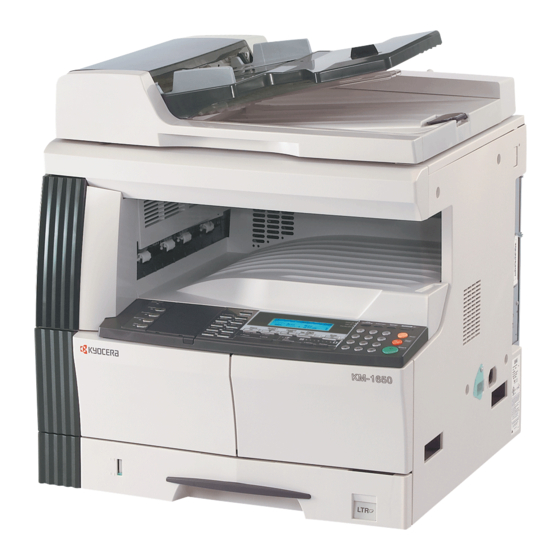
2DA/2DB 1-1-2 Parts names (1) MFP Figure 1-1-1 Original cover 10. Support guide 19. Front cover Copy storage section 11. Slider 20. Power switch Operation panel 12. Contact glass 21. Power switch cover Drawer 1 13. Original size indicator plates 22. -
Page 18: Operation Panel
2DA/2DB (2) Operation panel Figure 1-1-2 System Menu/Counter key and indicator 20. Paper Select key / Right cursor key Copier key and indicator 21. Enter key Printer key and indicator 22. Image quality mode select key Scanner key and indicator 23. -
Page 19: Machine Cross Section
2DA/2DB 1-1-3 Machine cross section Light path Paper path Figure 1-1-3 Machine cross section Paper feed section Optical section Drum section Developing section Transfer and separation section Fixing section Exit and switchback section Duplex section 1-1-5... -
Page 20: Drive System
2DA/2DB 1-1-4 Drive system Figure 1-1-4 Drive motor gear 15. Developing gear 25 Gear 122 16. Developing gear 26 Registration gear 51 17. Fixing joint gear 29 Registration motor gear 18. Gear 40 Gear 32 19. Gear 40 Gear 25 20. -
Page 21: Drum
2DA/2DB 1-2 Handling Precautions 1-2-1 Drum Note the following when handling or storing the drum. When removing the drum unit, never expose the drum surface to strong direct light. ° ° ° ° Keep the drum at an ambient temperature between -20 C/-4 F and 55 C/131... -
Page 22: Installation Environment
2DA/2DB-1 1-2-3 Installation environment ° ° Temperature: 10 - 32.5 C/50 - 90.5 Humidity: 15 - 80%RH Power supply: 120 V AC, 9.0 A 220 - 240 V AC, 5.0 A ± ± Power source frequency: 50 Hz 0.3%/60 Hz 0.3% Installation location Avoid direct sunlight or bright lighting. -
Page 23: Installation
2DA/2DB 1-3 Installation 1-3-1 Unpacking and installation (1) Installation procedure Start Unpacking. Install the optional paper feeder. Installing the toner (maintenance item U130). Remove the tapes and pins. Load paper. Install the original cover or the optional DP. Output an own-status report Install the optional duplex unit. - Page 24 2DA/2DB Unpacking. 16 ppm model Figure 1-3-1a Unpacking 10. Left spacer 19. Original holder Power cord 11. Rear spacer (Asia and Oceania) Toner container 12. Rear pad 20. Operation guide Outer case 13. Skid Cassette size sheet Lower left pad 14.
- Page 25 2DA/2DB 20 ppm model Figure 1-3-1b Unpacking 10. Left spacer 19. Original holder Power cord 11. Rear spacer (Asia and Oceania) Toner container 12. Rear pad 20. Front pad Outer case 13. Skid 21. Operation guide Lower left pad 14. Belt Cassette size sheet Lower right pad 15.
- Page 26 2DA/2DB Install the optional paper feeder. 1. Install the optional paper feeder as necessary (see pages 1-3-7 to 1-3-8). Remove the tapes and pins. 1. Remove the ten tapes (16 ppm model). Remove the fifteen tapes (20 ppm model).. 16 ppm model Tape Tapes Tape...
- Page 27 2DA/2DB-1 Install the original cover or the optional DP. 1. Install the original cover or optional DP (see pages 1-3-9 to 1-3-12 when installing the DP). Install the optional duplex unit. 1. Install the optional duplex unit as necessary (see pages 1-3-13 to 1-3-15). Install the optional finisher or job separator.
-
Page 28: Setting Initial Copy Modes
2DA/2DB-3.0 Load paper. 1. Load paper in the drawer. Output an own-status report (maintenance item U000). 1. Enter "000" using the numeric keys and press the start key. 2. Select "MAINTENANCE" and press the start key to output a list of the current settings of the maintenance items. -
Page 29: Installing The Paper Feeder (Option)
2DA/2DB-1 1-3-3 Installing the paper feeder (option) <Procedure> 1. Place the MFP on the paper feeder by align- ing the positioning insertion sections of the MFP with the positioning pins at the rear part of the paper feeder. * When placing the MFP, take care not to hit the MFP against the drawer, the pins or ground plate of the paper feeder. - Page 30 2DA/2DB-1 Adjusting the leading edge timing 1. Run maintenance mode 034. Select ADJ, RCL ON TIMING and press the start key. First optional cassette: Select RCL T1. Second optional cassette: Select RCL T2. Third optional cassette: Select RCL T3. For models equipped with two standard cassettes, adjust only RCL T2 and RCL T3. Press the Interrupt key to output the test pattern and check the image.
- Page 31 2DA/2DB-1 Installing the drawer heater (option) Drawer heater installation requires the following parts: Drawer heater (P/N 120 V specifications: 2A727480, 220-240 V specifications: 2A727490) Ground plate (P/N 3BG02060) Drawer heater mounting plate (P/N 3HW02030) One (1) M3 x 6 tap-tight S binding screw (P/N B3023060) <Procedure>...
- Page 32 2DA/2DB-1 7. Fit the three holes on the front of the drawer heater mounting plate to the positioning por- tion and the fitting portions on the front side of the machine. Fitting portion Positioning portion Fitting portion Drawer heater mounting plate Figure 1-3-9-3 8.
-
Page 33: Installing The Dp (Option)
2DA/2DB 1-3-4 Installing the DP (option) <Procedure> 1. Remove the original holder and remove the two screws from the rear top cover. Screw 2. Pass the two pins through the screw holes of the rear top cover and attach them to the Screw lower frame. - Page 34 2DA/2DB 5. Close the DP, fit the fixing fitting from the rear side of the right hinge, and secure it with the two bronze TP screws M3 x 06. 6. Connect the cable of the DP to the MFP. * Be sure to tighten the fixing screws on both side of the connector.
- Page 35 2DA/2DB-3.0 Maintenance mode 070 (sub-scan line adjustment) 1. Run maintenance mode 070. Select CONVEY SPEED1. (For adjustment of the back side in duplex copying, select CONVEY SPEED2.) Set originals in the original tray and press the interrupt key. Make a test copy to check the image. If an adequate image cannot be obtained, carry out the following adjustment.
- Page 36 2DA/2DB Maintenance mode 072 (center line adjustment) 1. Run maintenance mode 072. Select 1sided. (For adjustment of the front side in duplex copying, select 2sided front. For adjustment of the back side, select 2sided back.) Set originals in the original tray and press the Interrupt key. Make a test copy to check the image. If an adequate image cannot be obtained, carry out the following adjustment.
-
Page 37: Installing The Duplex Unit (Option)
2DA/2DB-3.0 1-3-5 Installing the duplex unit (option) <Procedure> 1. Open the left cover. 2. Remove the stop ring and the strap from the rear side. 3. Restore the conveyor section. 4. Remove the pin and plate, and then remove the stopper from the front side. 5. - Page 38 2DA/2DB-1 8. Press the duplex unit in the direction indi- Duplex unit cated by the arrow to fit the claws into the conveyer unit. Claws Claw Figure 1-3-22-1 9. Hang the hook of the plate lock on the con- veying unit and then turn the plate lock to fit the hole to the claw of the duplex unit.
- Page 39 2DA/2DB-1 11. Open the conveyer unit and connect the connector of the duplex unit to the MFP. 12. Reattach the removed parts to their original positions. 13. Connect the MFP power plug to the wall out- let and turn the power switch on. Duplex unit Connector Figure 1-3-24...
-
Page 40: Installing The Drawer Heater (Option)
2DA/2DB-1 1-3-6 Installing the drawer heater (option) Drawer heater installation requires the following parts: Drawer heater (P/N 120 V specifications: 2C960030, 220-240 V specifications: 2C960040) One (1) M4 x 10 tap-tight S binding screw (P/N B3024100) <Procedure> 1. Remove the main body from the paper feeder (see page 1-6-7). - Page 41 2DA/2DB 4. Insert the cassette heater from the bottom of the machine and attach it to the MFP. 1) Pass the connector of the cassette heater through the hole located in the right frame of the machine to pull it out. 2) Insert the projections at the rear side of Holes in the rear frame the cassette heater mounting plate into the...
- Page 42 2DA/2DB 5. Remove the two screws and open the power source PCB in the direction indicated by the Wire of the drawer heater arrow. * Take care not to open the power source PCB too much. 6. Fit the wire of the drawer heater into the groove of the frame and put it inside the power source PCB.
-
Page 43: Installing The Key Counter (Option)
2DA/2DB 1-3-7 Installing the key counter (option) Key counter installation requires the following parts: Key counter cover (P/N 2A360010) Key counter retainer (P/N 66060030) Key counter mount (P/N 66060040) Key counter assembly (P/N 41529210) Four (4) M4 x 6 bronze TP-A screws (P/N B4304060) One (1) M4 x 35 round head screw (P/N B0004350) Two (2) M3 x 6 bronze flat-head screws (P/N B2303060) One (1) M3 bronze nut (P/N C2303000) - Page 44 2DA/2DB 3. Remove the rear cover. Aperture 4. Cut out the aperture plate on the right cover 4-pin connector using nippers. 7-pin connector 5. Connect the 4-pin connector of the key counter wire (located at a longer distance from the tube) to YC13 on the engine PCB, Clamp pass the wire through the two clamps, and pull the other 4-pin connector out from the...
- Page 45 2DA/2DB 8. Connect the 4-pin connector of the key counter to the key counter wire. 9. Engage the projection of the key counter mounting plate with the aperture of the right cover. 10. Secure the key counter cover and the key counter mounting plate together with the MFP using a M4 x 35 screw.
-
Page 46: Installing The Finisher (Option)
2DA/2DB 1-3-8 Installing the finisher (option) <Note> When placing the transfer unit on the floor or the like, be sure to place it upside down. If not, the Transfer unit staple mounting plate may be deformed, resulting in a malfunction. Figure 1-3-35 Be sure to remove the tape for the intermediate Intermediate tray... - Page 47 2DA/2DB 2. Open the front cover. 3. Remove the inner cover. Inner cover Figure 1-3-38 4. Release the fitting parts using a small screw driver or the like and remove the front side cover. Fitting parts Front side cover Figure 1-3-39 5.
- Page 48 2DA/2DB 7. Remove the three screws and then remove Inner ejection cover the ejection cover and inner ejection cover. Ejection cover Screws Screw Figure 1-3-41 8. Remove the two screws and then remove the cover. Screws Cover Figure 1-3-42 1-3-24...
- Page 49 2DA/2DB Attach the transfer unit. 9. Insert the transfer unit from the MFP front side and slide it to the left to install to the ejection part. 10. Place the transfer unit closer to the ejection side and then secure the front side using the TP bind screw M3 x 06 and the rear side using the pin.
- Page 50 2DA/2DB Attach the intermediate tray. 12. Loosen the screw located inside of the MFP by about 3 turns. * Do not turn the screw too much, otherwise it may drop in the machine. 13. Hang the hook of the hook holder onto the screw and then retighten the screw.
- Page 51 2DA/2DB 15. Fit the pin located at the left rear side of the 24-pin connector 13-pin connector intermediate tray from the rear side of the MFP onto the hook of the transfer unit. 16. Remove the tape and pull out the 13-pin connector and 24-pin connector.
- Page 52 2DA/2DB 21. Attach the front ejection cover and rear ejec- Rear ejection cover tion cover using the TP bind screw M3 x 06 each. Front ejection cover TP bind screw M3 x 06 TP bind screw M3 x 06 Figure 1-3-50 22.
- Page 53 2DA/2DB 26. Insert the front and rear hooks of the copy tray into the front ejection cover and rear ejection cover each and then attach the copy tray. Rear ejection cover Copy tray Front ejection cover Figure 1-3-52 27. Open the staple cover and then insert the staple cartridge into the staple unit.
-
Page 54: Installing The Job Separator (Option)
2DA/2DB 1-3-9 Installing the job separator (option) <Procedure> Remove the covers. 1. Open the front cover. 2. Remove the inner cover. Inner cover Figure 1-3-54 3. Release the fitting parts using a small screw driver or the like and remove the front side cover. - Page 55 2DA/2DB 5. Remove the three screws and then remove Inner ejection cover the ejection cover and inner ejection cover. Ejection cover Screw Screws Figure 1-3-57 6. Remove the two screws and then remove the cover. Screws Cover Figure 1-3-58 1-3-31...
- Page 56 2DA/2DB-1 Attach the job separator. 7. Insert the job separator from the MFP front side and slide it to the left to install to the ejection part. 8. Place the job separator closer to the ejection side and then secure the front side (left tapped hole) with the large pin and the rear side with the small pin.
- Page 57 2DA/2DB Attach the copy tray. 12. Insert the left part of the copy tray into the groove of the job separator. Fit the right hook into the hole located inside of MFP while pushing the copy tray to the back along the groove.
- Page 58 2DA/2DB 14. Connect the pulled out connector of the job LED PCB separator to the LED PCB of the left front Connector cover JS and then pass the wire through the two positions of the groove of the left front cover JS.
-
Page 59: Installing The Fax System (Option)
2DA/2DB 1-3-10 Installing the fax system (option) <Procedure> Install the optional Memory module DIMM (32MB). 1. Remove the two connectors of the fax con- Screws trol PCB assembly. Fax control PCB assembly 2. Remove the three screws and remove the mounting plate and the ground wire. - Page 60 2DA/2DB Remove the shield cover. 7. Remove the six screws, lift the shield cover Shield cover and then remove the cover. Screws Screws Figure 1-3-67 Remove the modular cover. 8. Remove the screw and take off the modular cover. Screw Modular cover Figure 1-3-68 Attach the fax control PCB assembly.
- Page 61 2DA/2DB 11. Connect the YC1 connector on the fax control PCB assembly to the YC15 connector on the engine PCB. 12. Insert the fax control PCB assembly to the shield box so that the projection of the fax control PCB assembly is positioned to the slit of the shield box.
- Page 62 2DA/2DB Attach the modular cover. 16. Attach the modular cover that has been removed by Procedure 8 with the screw to the position shown in the illustration. Screw Modular cover Figure 1-3-73 Install the shield cover. 17. Insert the lower part of the shield cover that has been removed by Procedure 7 into the shield box and then attach it with the six screws and TP tap tight screw M4 x 6 to its...
- Page 63 2DA/2DB Attach the operation section sheet for fax. 19. Insert the small screw driver into the two Opening points of the opening and remove the left Left cover of cover of the operation section. the operation section Figure 1-3-76 20. Lift the two pawls and remove the operation section sheet cover.
- Page 64 2DA/2DB 22. Fit in the right-side two pawls of the opera- tion section sheet cover that has been removed by Procedure 20 and then attach Operation section sheet cover the operation section sheet cover to its origi- Pawl nal position. Pawl Figure 1-3-79 Attach the one-touch securing sheet.
- Page 65 2DA/2DB Attach the cover plate. 27. Incurvate the cover plate a little and then insert the upper and lower projections to the fitting parts of the operation section to attach. 28. Check that the cover plate smoothly moves on either side. Projection Cover plate Projection...
- Page 66 2DA/2DB Attach the alphabet labels. 30. Take the alphabet labels from the one-touch Alphabet labels label sheet, and adhere them above the cor- responding numeric keys on the operation panel after wiping the panel with alcohol. In Asia and Oceania, use the PQRS TUV WXYZ label, and do not use the PRS TUV WXZ and OPER labels.
-
Page 67: Installing The Scan System (Option)
2DA/2DB 1-3-11 Installing the scan system (option) <Procedure> Shield cover Remove the covers. Cover 1. Remove the six screws (a), lift the shield cover and then remove the cover. If the fax system is installed, remove the six screws (a) and screw (b), lift the shield cover and then remove the cover. - Page 68 2DA/2DB Install the shield cover. 5. Insert the lower part of the shield cover that Shield cover has been removed by Procedure 1 into the Screw (a) shield box and refit it to its original position using the six screws (a). If the fax system is installed, refit the shield Screw (a) cover using the six screws (a) and screw (b)
-
Page 69: Installing The Hard Disk (Option)
2DA/2DB 1-3-12 Installing the hard disk (option) <Procedure> 1. Remove the two screws of the slot for OPT2 which is on the machine right back, and then remove the cover. Socket 2. Insert the hard disk in the socket on the printer board PCB. -
Page 70: Maintenance Mode
2DA/2DB 1-4 Maintenance Mode 1-4-1 Maintenance mode The machine is equipped with a maintenance function which can be used to maintain and service the machine. (1) Executing a maintenance item Start Enter “10871087” using Maintenance mode is entered. the numeric keys. Enter the maintenance item number using the up/down cursor keys The maintenance item is... -
Page 71: Maintenance Modes Item List
2DA/2DB-3.0 (2) Maintenance modes item list Section Item Content of maintenance item Initial setting* General U000 Outputting an own-status report U001 Exiting the maintenance mode U002 Setting the factory default data U003 Setting the service telephone number *************** U004 Displaying the machine number U005 Copying without paper U019... - Page 72 2DA/2DB-3.0 Section Item Content of maintenance item Initial setting* High voltage U100 Checking the operation of main high voltage 132/60/50/10 U101 Setting high voltages Developing bias 27/45/22/45 Transfer voltage 166/177/37/35 Separation voltage 1/35/42 U110 Checking/clearing the drum count Developing U130 Initial setting for the developer U144 Setting toner loading operation...
- Page 73 2DA/2DB-3.0 Section Item Content of maintenance item Initial setting* Mode setting U343 Switching between duplex/simplex copy mode U344 Setting preheat/energy saver mode Inch specifications: ENERGY STAR Metric specifications: GEEA U345 Setting the value for maintenance due indication Image U402 Adjusting margins of image printing 3.0/3.0/4.0 processing U403...
-
Page 74: Contents Of The Maintenance Mode Items
2DA/2DB (3) Contents of the maintenance mode items Maintenance Description item No. Outputting an own-status report U000 Description Outputs lists of the current settings of the maintenance items, and paper jam and service call occurrences. Purpose To check the current setting of the maintenance items, or paper jam or service call occurrences. Before initial- izing or replacing the backup RAM, output a list of the current settings of the maintenance items to reenter the settings after initialization or replacement. - Page 75 2DA/2DB Maintenance Description item No. Setting the service telephone number U003 Description Sets the telephone number to be displayed when a service call code is detected. Purpose To set the telephone number to call service when installing the machine. Method Press the start key.
- Page 76 2DA/2DB Maintenance Description item No. Copying without paper U005 Description Simulates the copy operation without paper feed. Purpose To check the overall operation of the machine. Method 1. Press the start key. The screen for selecting an item is displayed. 2.
- Page 77 2DA/2DB Maintenance Description item No. Displaying the ROM version U019 Description Displays the part number of the ROM fitted to each PCB. Purpose To check the part number or to decide if the ROM version is new from the last digit of the number. Method 1.
- Page 78 2DA/2DB Maintenance Description item No. Initializing backup memory U022 Description Initializes only the data set for the optical section or initializes various setting data when installing the optional network scanner board. Purpose To be executed after replacing the scanner unit or installing the network scanner board. Method 1.
- Page 79 2DA/2DB Maintenance Description item No. Return of backup data U027 Description Transfers the backup data of the EEPROM which was transferred with the U026 to flash memory. Purpose To use after the main PCB replaced. Method 1. Press the start key. The screen for executing is displayed. 2.
- Page 80 2DA/2DB Maintenance Description item No. Checking switches for paper conveying U031 Description Displays the on-off status of each paper detection switch on the paper path. Purpose To check if the switches for paper conveying operate correctly. Method 1. Press the start key. A list of the switches, the on-off status of which can be checked, are displayed. 2.
- Page 81 2DA/2DB-3.0 Maintenance Description item No. Setting folio size U035 Description Changes the image area for copying onto folio size paper. Purpose To prevent the image at the trailing edge, or right or left side of the paper from not being copied by setting the actual size of the folio paper used.
- Page 82 2DA/2DB-3.0 Maintenance Description item No. U053 Display Description Setting range Initial setting RES1 Trailing edge registration motor correction 0 to +5.0 (paper feed from drawer) RESB Trailing edge registration motor correction 0 to +5.0 (paper feed from bypass tray) RES2 Trailing edge registration motor correction 0 to +5.0 (paper feed from first paper feeder...
- Page 83 2DA/2DB Maintenance Description item No. Adjusting the scanner input properties U060 Description Adjusts the image scanning density in text, text and photo, or photo mode. Purpose Used when the entire image appears too dark or light. Method Press the start key. The screen for setting is displayed. Setting 1.
- Page 84 2DA/2DB-1 Maintenance Description item No. Adjusting the shading position U063 Description Changes the shading position. Purpose Used when white lines continue to appear longitudinally on the image after the shading plate is cleaned. This is due to flaws or stains inside the shading plate. To prevent this problem, the shading position should be changed so that shading is possible without being affected by the flaws or stains.
- Page 85 2DA/2DB Maintenance Description item No. Adjusting the DP magnification U070 Description Adjusts the DP original scanning speed. Purpose To be executed if the correct magnification is not obtained in the auxiliary scanning direction when the optional DP is used. Caution Before making this adjustment, ensure that the following adjustments have been made in maintenance mode.
- Page 86 2DA/2DB Maintenance Description item No. Adjusting the DP scanning timing U071 Description Adjusts the DP original scanning timing. Purpose To be executed if there is a regular error between the leading or trailing edges of the original and the copy image when the optional DP is used.
- Page 87 2DA/2DB Maintenance Description item No. Adjusting the DP center line U072 Description Adjusts the scanning start position for the DP original. Purpose To be executed if there is a regular error between the centers of the original and the copy image when the optional DP is used.
- Page 88 2DA/2DB Maintenance Description item No. Checking scanner operation U073 Description Simulates the scanner operation under arbitrary conditions. Purpose To check scanner operation. Method 1. Press the start key. The screen for selecting an item is displayed. 2. Select the item to be changed using the up/down cursor keys. The selected item is displayed in reverse. 3.
- Page 89 2DA/2DB-3.0 Maintenance Description item No. Executing DP automatic adjustment U076 Description Uses a specified original and automatically adjusts the following items in the DP scanning section. Adjusting the DP magnification (U070) Adjusting the DP scanning timing (U071) Adjusting the DP center line (U072) When you run this maintenance mode, the preset values of U070, U071 and U072 will also be updated.
- Page 90 2DA/2DB Maintenance Description item No. Turning the DP scanning position adjust mode on/off U087 Description Turns on or off the DP scanning position adjust mode, in which the DP original scanning position is adjusted automatically by determining the presence or absence of dust on the slit glass. Also changes the reference data for identifying dust.
- Page 91 2DA/2DB-3.0 Maintenance Description item No. Outputting a MIP-PG pattern U089 Description Selects and outputs the MIP-PG pattern created in the machine. Purpose When performing respective image printing adjustments, used to check the machine status apart from that of the scanner with a non-scanned output MIP-PG pattern. Method 1.
- Page 92 2DA/2DB-3.0 Maintenance Description item No. Adjusting the scanner automatically U092 Description Makes auto scanner adjustments in the order below using the specified original. Adjusting the scanner center line (U067) Adjusting the scanner leading edge registration (U066) Adjusting scanner magnification in the auxiliary direction (U065) When this maintenance item is performed, the settings in U065, U066 and U067 are also changed.
- Page 93 2DA/2DB Maintenance Description item No. Setting the exposure density gradient U093 Description Changes the exposure density gradient in manual density mode, depending on respective image modes (text, text and photo, photo, text in fax mode, photo in fax mode). Purpose To set how the image density is altered by a change of one step in the manual density adjustment.
- Page 94 2DA/2DB-3.0 Maintenance Description item No. Setting: Density in photo mode U093 1. Select the item to be adjusted using the up/down cursor keys. The selected item is displayed in reverse. 2. Adjust the setting using the left/right cursor keys. Display Description Setting range Initial setting...
- Page 95 2DA/2DB Maintenance Description item No. Checking the original size detection U099 Description Checks the operation of the original size detection sensor and sets the sensing threshold value. Purpose To adjust the sensitiveness of the sensor and size judgement time if the original size detection sensor mal- functions frequently due to incident light or the like.
- Page 96 2DA/2DB-1 Maintenance Description item No. Setting the main high voltage U100 Description Changes the surface potential by changing the grid control voltage. Also performs main charging. Also changes the setting of main charging copy quantity correction. Purpose To set the surface potential or check main charging. Also used when reentering data after initializing the set data.
- Page 97 2DA/2DB-1 Maintenance Description item No. Setting the other high voltages U101 Description Changes the developing bias voltage and transfer/separation voltage. Purpose To check the developing bias and the transfer/separation voltage or to take measures against drop of image density or background fog. Method 1.
- Page 98 2DA/2DB-1 Maintenance Description item No. Checking/clearing the drum count U110 Description Displays the drum counts for checking, clearing the figure. Purpose To check the drum status. Also used to clear the count after replacing the durm during regular maintenance. Since the count was cleared before shipping, do not clear it when installing. A drum count value less than 150K, however, cannot be cleared.
- Page 99 2DA/2DB Maintenance Description item No. Checking/clearing the developing drive time U157 Description Displays the developing drive time for checking, clearing or changing a figure. Purpose To check the developing drive time. Also used to clear the count after replacing the developing unit. Method Press the start key.
- Page 100 2DA/2DB Maintenance Description item No. Stabilizing fixing forcibly U162 Description Stops the stabilization fixing drive forcibly, regardless of fixing temperature. Purpose To forcibly stabilize the machine before the fixing section reaches stabilization temperature. Method 1. Press the start key. The screen for executing is displayed. 2.
- Page 101 2DA/2DB Maintenance Description item No. Turning all LEDs on U200 Description Turns all the LEDs on the operation panel on. Purpose To check if all the LEDs on the operation panel light. Method Press the start key. All the LEDs on the operation panel light. Press the stop/clear key or wait for 10 s.
- Page 102 2DA/2DB-3.0 Maintenance Description item No. Setting the presence or absence of a key card or key counter U204 Description Sets the presence or absence of the optional key card or key counter. Purpose To run this maintenance item if a key card or key counter is installed. Setting 1.
- Page 103 2DA/2DB Maintenance Description item No. Checking the operation of the DP motors and solenoids U243 Description Turns the motors or solenoids in the optional DP on. Purpose To check the operation of the DP motors and solenoids. Method 1. Press the start key. The screen for selecting an item is displayed. 2.
- Page 104 2DA/2DB Maintenance Description item No. Checking messages U245 Description Displays a list of messages or graphics on the operation panel. Purpose To check the messages or graphics to be displayed. Method 1. Press the start key. The screen for selecting an item is displayed. 2.
- Page 105 2DA/2DB Maintenance Description item No. Checking the paper ejection to optional devices U249 Description Ejects paper to an optional job separator. Purpose To check paper conveying operation to optional job separator. Method While pressing the feedshift switch by your hand, press the start key. Paper transfer operation starts. Completion Press the stop/clear key.
- Page 106 2DA/2DB-3.0 Maintenance Description item No. Checking/clearing the maintenance count U251 Description Displays, clears and changes the maintenance count. Purpose To check the maintenance count. Also to clear the count during maintenance service. Method Press the start key. The maintenance count is displayed. Clearing 1.
- Page 107 2DA/2DB Maintenance Description item No. Switching between double and single counts U253 Description Switches the count system for the total counter and other counters. Purpose According to user (copy service provider) request, select if A3/11" x 17" paper is to be counted as one sheet (single count) or two sheets (double count).
- Page 108 2DA/2DB Maintenance Description item No. Switching copy operation at toner empty detection U258 Description Selects if continuous copying is enabled after toner empty is detected, and sets the number of copies that can be made after the detection. Purpose To be set according to user request. Method Press the start key.
- Page 109 2DA/2DB Maintenance Description item No. Setting the display order of the date U264 Description Selects year, month and day as the order of that appears on lists, etc. Purpose Set according to the user preference. Method Press the start key. The screen for selecting an item is displayed. Setting 1.
- Page 110 2DA/2DB Maintenance Description item No. Setting the black line cleaning indication U326 Description Sets whether to display the cleaning guidance when detecting the black line. Purpose Displays the cleaning guidance in order to make the call for service with the black line decrease by the rubbish on the contact glass when scanning from the optional DP.
- Page 111 2DA/2DB Maintenance Description item No. Specific paper feed location setting for printing function U341 Description Sets a paper feed location specified for printer output. Purpose To use a paper feed location only for printer output. Method 1. Press the start key. The screen for selecting an item is displayed. 2.
- Page 112 2DA/2DB-1 Maintenance Description item No. Switching between duplex/simplex copy mode U343 Description Switches the initial setting between duplex and simplex copy. Purpose To be set according to frequency of use: set to the more frequently used mode. Method Press the start key. The screen for selecting an item is displayed. Setting 1.
- Page 113 2DA/2DB-1 Maintenance Description item No. Adjusting margins for scanning an original from the DP U404 Description Adjusts margins for scanning the original from the DP. Purpose Used if margins are not correct when the optional DP is used. Caution Before making this adjustment, ensure that the following adjustments have been made in maintenance mode. U402 U403 U404...
- Page 114 2DA/2DB Maintenance Description item No. Initializing the scanner NIC U504 Description Initializing the optional scanner NIC to its factory default. Purpose To return to a setup at the time of factory shipments. Method 1. Press the start key. The screen for executing is displayed. 2.
- Page 115 2DA/2DB Maintenance Description item No. Checking/clearing copy counts by paper feed locations U901 Description Displays or clears copy counts by paper feed locations. Purpose To check the time to replace consumable parts. Also to clear the counts after replacing the consumable parts. Method 1.
- Page 116 2DA/2DB Maintenance Description item No. Checking/clearing the service call counts U904 Description Displays or clears the service call code counts by types. Purpose To check the service call code status by types. Also to clear the service call code counts after replacing con- sumable parts.
- Page 117 2DA/2DB Maintenance Description item No. Resetting partial operation control U906 Description Resets the service call code for partial operation control. Purpose To be reset after partial operation is performed due to problems in the drawers or other sections, and the related parts are serviced.
- Page 118 2DA/2DB Maintenance Description item No. Setting backup data reading/writing U917 Description Stores backup data from the fax control PCB (when an optional fax kit is installed) into Compact Flash or reads the data from Compact Flash. Purpose To store and write data when replacing the PCB. Setting 1.
- Page 119 2DA/2DB Maintenance Description item No. Checking the accounting counts U920 Description Checks the accounting counts. Purpose To check the accounting counts. Method Press the start key. The current counts of copy counter, printer counter and fax counter are displayed. Completion Press the stop/clear key.
- Page 120 2DA/2DB-1 Maintenance Description item No. U926 If the operation was successful: EXECUTE 0100 CHECKSUM **** CODE 0000 If the operation failed: EXECUTE 0100 CHECKSUM **** CODE XXXX Where XXX is the error code indicating the reason for the failure. See "Error Codes for Operation U917 and U926"...
- Page 121 2DA/2DB-3.0 Maintenance Description item No. Adjusting the DP amount of slack in the original U942 Description Adjusts the DP amount of slack in the original. Purpose To run this mode if original jams or Z folds occur when copying from the DP. Method Press the start key.
- Page 122 2DA/2DB Maintenance Description item No. Checking the scanner count U991 Description Displays the scanner operation count. Purpose To check the status of use of the scanner. Method Press the start key. The screen for the scanner operation count is desplayed. Display Description COPY...
-
Page 123: Management Mode
2DA/2DB-1 1-4-2 Management mode In addition to a maintenance function for service, the machine is equipped with a management function which can be oper- ated by users (mainly by the machine administrator). In this management mode, settings such as default settings can be changed. -
Page 124: Setting The Job Accounting
2DA/2DB-1 (2) Setting the job accounting Job accounting ON/OFF Registering a new account 1. Select [Job Accounting On/Off] and then press the Registers ID-codes and the limit of use for each enter key. account. 2. Select [On] or [Off] and then press the enter key. 1. -
Page 125: Copy Default
2DA/2DB-1 (3) Copy default Default drawer Exposure mode Sets one drawer that will be selected automatically Selects the exposure mode at power-on. regardless of the size of paper loaded in that drawer. 1. Select [Exposure Mode] and then press the enter 1. - Page 126 2DA/2DB-1 Manual exposure adjustment (text mode) Adjusts the median exposure value when the text Copy limit mode is selected for the image quality. Sets the limit for the number of copies (or copy sets) 1. Select [Txt Ori Density] and then press the enter that can be made at a time.
-
Page 127: Machine Default
2DA/2DB-1 (4) Machine default Custom paper type Auto drawer switching ON/OFF Sets whether or not to match the orientation in one- Turns automatic drawer switching ON or OFF. sided printing and two-sided printing. 1. Select [Auto Cassette SW] and then press the enter 1. - Page 128 2DA/2DB-1 Default operation mode Auto clear time Sets whether the display that appears after power is Sets the time that elapses from completion of copying turned on to the machine will be the one for the copy to activation of the auto cler function. operation mode or for the fax operation mode.
-
Page 129: Bypass Setting
2DA/2DB-1 (5) Bypass setting (6) Checking the total counter and printing out the counter report Paper size and type Sets the paper size and paper type for the bypass set- Checks the total count of copies, etc., and prints out tings. -
Page 130: Paper Misfeed Detection
2DA/2DB 1-5 Troubleshooting 1-5-1 Paper misfeed detection (1) Paper misfeed indication When a paper misfeed occurs, the machine immediately stops operating and displays the jam location on the operation panel. Paper misfeed counts sorted by the detection condition can be checked in maintenance item U903. To remove paper jammed in the machine, open the front cover, left cover, or pull the drawer out. -
Page 131: Paper Misfeed Detection Conditions
2DA/2DB (2) Paper misfeed detection conditions OCM OFM OSBSW DPTSW PCSW FSSW DUPPCSW DUPFCL BYPPFSOL PFCL DPFCL1 DFSW1 DPFCL2 DFSW2 DPFCL3 Figure 1-5-2 1-5-2... - Page 132 2DA/2DB Section Jam code Description Conditions System No paper feed When the power switch is turned on, the machine detects acti- vation of the registration switch (RSW), the exit switch (ESW) or the feedshift switch (FSSW). Cover open JAM A cover open state is detected during copying. Secondary paper feed When the machine waits for secondary paper feed, 30 s or timeout...
- Page 133 2DA/2DB Section Jam code Description Conditions Paper Multiple sheets in the The registration switch (RSW) does not turn off within 6320 ms conveying of registration switch (RSW) turning on. drawer 2* (first paper section The registration switch (RSW) does not turn off within 2780 ms feeder) of drawer paper feed clutch 1 (DPFCL1)* turning on.
- Page 134 2DA/2DB Section Jam code Description Conditions Feedshift Misfeed in the feedshift The feedshift switch (FSSW) does not turn on within 6320 ms section section (paper feed from of feedshift switch (FSSW) turning on. bypass tray) The feedshift switch (FSSW) does not turn off within 1530 ms of paper switchback.
- Page 135 2DA/2DB Section Jam code Description Conditions During the primary feed of the second original in the single- No original feed* sided or double-sided original mode, even if retry operation is performed five times, primary original feed is not performed. An original jam in the orig- During the secondary original feed in the single-sided or dou- inal conveying section 1* ble-sided original mode, the DP timing switch (DPTSW)*...
-
Page 136: Paper Misfeeds
2DA/2DB (3) Paper misfeeds Problem Causes/check procedures Corrective measures A piece of paper torn from Check visually and remove it, if any. A paper jam in the copy paper is caught paper feed, paper around registration switch, conveying or exit exit sensor or feedshift section is indicated switch. - Page 137 2DA/2DB Problem Causes/check procedures Corrective measures Paper in the first paper Change the paper. A paper jam in the feeder* is extremely paper feed section is curled. indicated during Check if the paper feed pul- Check visually and replace any deformed pulley. copying (no paper ley, separation pulley or for- feed from the drawer...
- Page 138 2DA/2DB Problem Causes/check procedures Corrective measures Check if the drawer paper Run maintenance item U032 and select the drawer paper feed A paper jam in the clutch 3 to be turned on and off. Check the status and remedy if feed clutch 3* malfunc- paper feed section is...
- Page 139 2DA/2DB Problem Causes/check procedures Corrective measures Broken drawer feed switch Check visually and replace drawer feed switch 1 if its actuator is A paper jam in the broken. actuator. paper feed section is Defective drawer feed Run maintenance item U031 and turn drawer feed switch 1 on indicated during and off manually.
- Page 140 2DA/2DB Problem Causes/check procedures Corrective measures (10) Electrical problem with the Check (see page 1-5-35). A paper jam in the paper feed clutch. paper conveying sec- Check if the right and left Check visually and remedy if necessary. tion is indicated dur- registration rollers contact ing copying (multiple each other.
- Page 141 2DA/2DB Problem Causes/check procedures Corrective measures (14) Deformed guides along the Repair or replace if necessary. A paper jam in the paper conveying path. transfer section is Broken registration switch Check visually and replace registration switch if its actuator is bro- indicated during actuator.
- Page 142 2DA/2DB Problem Causes/check procedures Corrective measures (16) Check if the registration Run maintenance item U030 and select the registration motor to A paper jam in the motor malfunctions. be turned on and off. Check the status and remedy if necessary. exit section is indi- Electrical problem with the Check (see page 1-5-34).
- Page 143 2DA/2DB Problem Causes/check procedures Corrective measures (20) Broken duplex paper con- Check visually and replace the duplex paper conveying switch if A paper jam in the its actuator is broken. veying switch* actuator. duplex section is indi- Defective duplex paper con- Run maintenance item U031 and turn duplex paper conveying cated during copying switch on and off manually.
- Page 144 2DA/2DB Problem Causes/check procedures Corrective measures (24) Check visually and replace DP timing switch if its actuator is bro- Broken DP timing switch* An original jams in ken. actuator. the original convey- Defective DP timing Run maintenance item U244 and turn DP timing switch on and off ing section is indi- manually.
- Page 145 2DA/2DB Problem Causes/check procedures Corrective measures (29) Defective paper conveying With 5 V DC present at CN4-9 on the finisher main PCB, check if A paper jam in the CN4-10 on the finisher main PCB remains high or low when the switch* finisher*1 is indi- paper conveying switch is turned on and off.
-
Page 146: Self-Diagnosis
2DA/2DB 1-5-2 Self-diagnosis (1) Self-diagnostic function This unit is equipped with a self-diagnostic function. When a problem is detected, copying is disabled. "C" and a number between 0030 and 8210 altenates, indicating the nature of the problem. A message is also displayed requesting the user to call for service. After removing the problem, the self-diagnostic function can be reset by power switch turns off and on. -
Page 147: Self Diagnostic Codes
2DA/2DB-3.0 (2) Self diagnostic codes Remarks Code Contents Causes Check procedures/corrective measures C0030 Defective fax con- Replace the fax control PCB and check for Fax control PCB* system problem trol PCB. correct operation. Processing with the fax software was disabled due to a hardware or software problem. - Page 148 2DA/2DB Remarks Code Contents Causes Check procedures/corrective measures C0210 Communication problem between the Poor contact in the Check the connection of connector. Repair main PCB and engine PCB connector termi- or replace if necessary. When the power is turned on, the nals.
- Page 149 2DA/2DB Remarks Code Contents Causes Check procedures/corrective measures C0510 Paper feeder Check the installation state of the paper Third paper feeder* communication installed incor- feeder and adjust it if it is not properly problem rectly. installed. Communication fails five times succes- sively.
- Page 150 2DA/2DB Remarks Code Contents Causes Check procedures/corrective measures C0890 Defective fax con- Replace the fax control PCB and check for Fax control PCB* CG font archive trol PCB. correct operation. problem When power is turned on, the com- pressed CG font in the Flash ROM on the fax control PCB was not successfully decompressed.
- Page 151 2DA/2DB Remarks Code Contents Causes Check procedures/corrective measures C3300 Optical system (AGC) problem Insufficient expo- Replace the exposure lamp or inverter PCB. After AGC, correct input is not obtained sure lamp luminos- at CCD. ity. Defective engine Replace the engine PCB and check for cor- PCB.
- Page 152 2DA/2DB Remarks Code Contents Causes Check procedures/corrective measures C6000 Broken fixing heater wire Fixing heater M or Check and reinstall if necessary. In fixing warm-up, the time to reach S installed incor- ° ° rectly. C/122 F exceeds 13.5 s, the time to °...
- Page 153 2DA/2DB Remarks Code Contents Causes Check procedures/corrective measures C7810 Short-circuited external temperature Poor contact in the Reinsert the connector. Also check for conti- thermistor humidity sensor nuity within the connector cable. If none, The input voltage is 4.5 V or more. connector termi- remedy or replace the cable.
- Page 154 2DA/2DB Remarks Code Contents Causes Check procedures/corrective measures C8190 The trailing edge Reinsert the connector. Also check for conti- Finisher* trailing edge registration registration motor nuity within the connector cable. If none, motor problem connector makes remedy or replace the cable. If the trailing edge registration home poor contact.
-
Page 155: Image Formation Problems
2DA/2DB 1-5-3 Image formation problems (1) No image (2) No image (3) Image is too (4) Background is (5) A white line appears appears light. visible. appears longitu- (entirely white). (entirely black). dinally. See page 1-5-27. See page 1-5-27. See page 1-5-28. See page 1-5-28. - Page 156 2DA/2DB (1) No image appears (entirely white). Causes 1. No transfer charging. 2. No LSU laser is output. 3. No developing bias is output. Causes Check procedures/corrective measures 1. No transfer charging. A. The connector terminals of the high-volt- Reinsert the connector. Also check for continuity within the connector age PCB make poor contact.
- Page 157 2DA/2DB (3) Image is too light. Causes 1. Insufficient toner. 2. The transfer voltage is not output properly. 3. Dirty main charger wire. 4. Dirty main charger grid. Causes Check procedures/corrective measures 1. Insufficient toner. If the display shows the message requesting toner replenishment, replace the container.
- Page 158 2DA/2DB (6) A black line appears longitudinally. Causes 1. Dirty contact glass. 2. Dirty or flawed drum. 3. Dirty scanner mirror. 4. Dirty main charger wire. Causes Check procedures/corrective measures 1. Dirty contact glass. Clean the contact glass. 2. Dirty or flawed drum. Clean the drum or, if it is flawed, replace the drum unit (see page 1-6-38).
-
Page 159: Image Is Blurred
2DA/2DB-1 (9) Black dots appear on the image. Causes 1. Dirty or flawed drum. 2. Dirty contact glass. 3. Deformed or worn cleaning blade. 4. Dirty drum separation claws. 5. Dirty heat roller separation claws. Causes Check procedures/corrective measures 1. Dirty or flawed drum. Clean the drum or, if it is flawed, replace the drum unit (see page 1-6-38). -
Page 160: The Leading Edge Of The Image Is Sporadically Misaligned With The Original
2DA/2DB (12) The leading edge of the image is Causes sporadically misaligned with the 1. Paper feed clutch, bypass paper feed solenoid or registration motor installed original. or operating incorrectly. Causes Check procedures/corrective measures 1. Paper feed clutch, bypass paper feed Check the installation position and operation of the paper feed clutch, solenoid or registration motor installed or bypass paper feed solenoid and registration motor. -
Page 161: Image Is Partly Missing
2DA/2DB-1 (15) Image is partly missing. Causes 1. Paper damp. 2. Paper creased. 3. Dirty or flawed drum. 4. Dirty transfer roller. Causes Check procedures/corrective measures 1. Paper damp. Check the paper storage conditions. 2. Paper creased. Replace the paper. 3. -
Page 162: Image Center Does Not Align With The Original Center
2DA/2DB (18) Image center does not align with Causes the original center. 1. Misadjusted center line of image printing. 2. Misadjusted scanner center line. 3. Original placed incorrectly. Causes Check procedures/corrective measures 1. Misadjusted center line of image printing. Readjust the center line of image printing (see page 1-6-18). 2. -
Page 163: Electric Problems
2DA/2DB 1-5-4 Electric problems Problem Causes Check procedures/corrective measures No electricity at the power Measure the input voltage. The machine does outlet. not operate when the The power cord is not Check the contact between the power plug and the outlet. power switch is plugged in properly. -
Page 164: The Scanner Motor Does Not Operate
2DA/2DB Problem Causes Check procedures/corrective measures Broken scanner motor coil. Check for continuity across the coil. If none, replace the scanner The scanner motor motor. does not operate. Poor contact in the scanner Reinsert the connector. Also check for continuity within the con- motor connector terminals. -
Page 165: The Exposure Lampdoes Not Turn Off
2DA/2DB Problem Causes Check procedures/corrective measures (12) Broken drawer paper feed- Check for continuity across the coil. If none, replace the drawer The drawer paper clutch coil. paper feed clutch. feed clutch* doesnot Poor contact in the drawer- Reinsert the connector. Also check for continuity within the con- operate. - Page 166 2DA/2DB Problem Causes Check procedures/corrective measures (19) Poor contact in the high See page 1-5-27. Transfer charging is voltage PCB connector ter- not performed. minals. Defective engine PCB. Defective high-voltage PCB. (20) Poor contact in the high See page 1-5-27. No developing bias is voltage PCB connector ter- output.
-
Page 167: Left Cover Are Closed
2DA/2DB Problem Causes Check procedures/corrective measures (27) A piece of paper torn from Check and remove if any. A paper jam in the copy paper is caught paper feed, paper around registration switch, conveying or fixing exit switch or feedshift section is indicated switch. -
Page 168: Mechanical Problems
2DA/2DB-1 1-5-5 Mechanical problems Problem Causes/check procedures Corrective measures Check if the surfaces of the following rollers or Clean with isopropyl alcohol. No primary paper feed. pulleys are dirty with paper powder: forward- ing pulley, paper feed pulley, separation pul- ley, registration rollers, bypass paper feed pulley, bypass separation pad, feed roller*, drawer forwarding pulley*, drawer paper feed... -
Page 169: Toner Drops On The Paper Conveying Path
2DA/2DB Problem Causes/check procedures Corrective measures Check if the developing unit is extremely dirty. Clean the developing unit. Toner drops on the paper conveying path. Check if the pulleys, rollers and gears operate Grease the bearings and gears. Abnormal noise is heard. smoothly. -
Page 170: Precautions For Assembly And Disassembly
2DA/2DB 1-6 Assembly and Disassembly 1-6-1 Precautions for assembly and disassembly (1) Precautions Be sure to turn the power switch off and disconnect the power plug before starting disassembly. When handling PCBs, do not touch connectors with bare hands or damage the board. Do not touch any PCB containing ICs with bare hands or any object prone to static charge. -
Page 171: Running A Maintenance Item
2DA/2DB (2) Running a maintenance item Start Enter “10871087” using Maintenance mode is entered. the numeric keys. Enter the maintenance item number using the up/down cursor keys The maintenance item is or numeric keys. selected. Press the start key. The selected maintenance item is run. Press the stop/clear key. -
Page 172: Paper Feed Section
2DA/2DB 1-6-2 Paper feed section (1) Detaching and refitting the separation pulley Follow the procedure below to replace the separation pulley. Procedure 1. Open the front cover and left cover. Remove the waste toner box. 2. Pull out the drawer. Drawer Figure 1-6-1 3. - Page 173 2DA/2DB 5. Remove the separation pulley unit from the lower paper feed unit. 6. Remove the separation pulley from the sep- aration pulley unit. 7. Replace the separation pulley and refit all the removed parts. Separation pulley Separation pulley unit Lower paper feed unit Figure 1-6-4 1-6-4...
-
Page 174: Detaching And Refitting The Forwarding Pulley And Paper Feed Pulley
2DA/2DB (2) Detaching and refitting the forwarding pulley and paper feed pulley Follow the procedure below to replace the forwarding pulley and paper feed pulley. Procedure Stop ring 1. Remove the lower paper feed unit (see page 1-6-3). 2. Remove the drum unit (see page 1-6-38). 3. - Page 175 2DA/2DB 7. Remove the springs, stop ring and bushing Shaft holder and then the shaft holder from the upper Spring paper feed unit. Spring Stop ring Upper paper feed unit Bushing Figure 1-6-8 8. Remove the forwarding pulley from the Paper feed pulley upper paper feed unit.
-
Page 176: Detaching And Refitting The Feed Roller (20 Ppm Model Only)
2DA/2DB-1 (3) Detaching and refitting the feed roller (20 ppm model only) Follow the procedure below to replace the feed roller. Procedure 1. Remove the rear cover, right cover and front left lower cover. 2. Remove the three screws and then remove the main body from the paper feeder. -
Page 177: Detaching And Refitting The Drawer Separation Pulley (20 Ppm Model Only)
2DA/2DB (4) Detaching and refitting the drawer separation pulley (20 ppm model only) Follow the procedure below to replace the drawer separation pulley. Procedure 1. Pull out the drawer. Open the drawer left cover. 2. Remove the screw and then the lower paper feed unit. -
Page 178: Detaching And Refitting The Drawer Forwarding Pulley And Drawer Paper Feed Pulley (20 Ppm Model Only)
2DA/2DB-1 (5) Detaching and refitting the drawer forwarding pulley and drawer paper feed pulley (20 ppm model only) Follow the procedure below to replace the drawer forwarding pulley and drawer paper feed pulley. Procedure 1. Remove the main body from the paper Stop ring Stop ring feeder (see page 1-6-7). - Page 179 2DA/2DB-1 6. Remove the springs, stop ring and bushing and then the shaft holder from the upper Shaft holder Spring paper feed unit. Spring Stop ring Upper paper feed unit Bushing Figure 1-6-15 7. Remove the drawer forwarding pulley from Drawer paper feed pulley the upper paper feed unit.
-
Page 180: Detaching And Refitting The Paper Conveying Unit
2DA/2DB-3.0 (6) Detaching and refitting the paper conveying unit Follow the procedure below to maintenance of the paper feed section. Procedure 1. Remove the drum unit (see page 1-6-38). 2. Remove the stop ring and strap from the rear side. Restore the paper conveying unit. Remove the pin and plate, and then remove the stopper from the front side. - Page 181 2DA/2DB 6. Push the fitting portions of the bypass upper cover. Remove the bypass upper cover from the bypass unit. Bypass upper cover Figure 1-6-19 7. Detach the connector and remove the bypass lower cover from the MFP. Connector Bypass lower cover Figure 1-6-20 8.
-
Page 182: Detaching And Refitting The Bypass Paper Feed Pulley And Bypass Separation Pad
2DA/2DB (7) Detaching and refitting the bypass paper feed pulley and bypass separation pad Follow the procedure below to replace the bypass paper feed pulley and bypass separation pad. Procedure 1. Open the front cover and remove the waste toner box. Pull out the drawer. 2. - Page 183 2DA/2DB 7. Temporarily push the bypass paper feed pul- Bypass paper feed pulley unit ley unit into the rear side to unlock the front side and then remove it from the MFP. Figure 1-6-25 8. Remove the bypass paper feed pulley from the bypass paper feed pulley shaft.
-
Page 184: Detaching And Refitting The Registration Left Roller
2DA/2DB (8) Detaching and refitting the registration left roller Follow the procedure below to replace the registration left roller. Procedure Stopper 1. Remove the paper conveying unit (see page 1-6-11). Paper conveying unit 2. Remove the transfer roller (see page 1-6- 42). -
Page 185: Adjustment After Roller And Clutch Replacement
2DA/2DB-3.0 (10) Adjustment after roller and clutch replacement Perform the following adjustment after refitting rollers and clutches. (10-1) Adjusting the leading edge registration of image printing Make the following adjustment if there is a regular error between the leading edges of the copy image and original. U066 U071 U034... -
Page 186: Adjusting The Leading Edge Registration For Memory Image Printing
2DA/2DB (10-2) Adjusting the leading edge registration for memory image printing Make the following adjustment if there is a regular error between the leading edge of the copy image and the leading edge of the original during memory copying. U066 U403 U053 U034... -
Page 187: Adjusting The Center Line Of Image Printing
2DA/2DB-3.0 (10-3) Adjusting the center line of image printing Make the following adjustment if there is a regular error between the center lines of the copy image and original when paper is fed from the drawer. U067 U072 U034 (P. 1-6-36) (P. -
Page 188: Adjusting The Trailing Edge Margin Of Image Printing
2DA/2DB (10-4) Adjusting the trailing edge margin of image printing Make the following adjustment if there is a regular error between the trailing edges of the copy image and original. Procedure Start Enter maintenance mode. Trailing edge margin Enter “034” using the numeric keys. Correct image Output example... -
Page 189: Adjusting The Margins For Printing
2DA/2DB-1 (10-5) Adjusting the margins for printing Make the following adjustment if the margins are not correct. U403 U404 U402 (P. 1-6-37) (P. 1-4-44) Caution: Check the copy image after the adjustment. If the margins are still incorrect, perform the above adjustments in mainte- nance mode. -
Page 190: Adjusting The Amount Of Slack In The Paper
2DA/2DB-1 (10-6) Adjusting the amount of slack in the paper Make the following adjustment if the leading edge of the copy image is missing or varies randomly, or if the copy paper is Z-folded. Procedure Start Enter maintenance mode. Original Copy Copy example 1... -
Page 191: Optical Section
2DA/2DB 1-6-3 Optical section (1) Detaching and refitting the exposure lamp Take the following procedure when the exposure lamp is to be replaced. Procedure Contact glass 1. Remove the original cover or the DP. 2. Remove the two screws holding the upper right cover and then the cover. -
Page 192: Detaching And Refitting The Scanner Wires
2DA/2DB (2) Detaching and refitting the scanner wires Take the following procedure when the scanner wires are broken or to be replaced. (2-1) Detaching the scanner wires Procedure Upper rear cover 1. Remove the exposure lamp (see page 1-6- 22). 2. - Page 193 2DA/2DB 5. Remove the screw holding each of the front and rear wire retainers and then remove the mirror 1 frame from the scanner unit. Mirror 1 frame Rear wire Front wire retainer retainer Figure 1-6-43 6. Unhook the round terminal of the scanner Round terminal wire from the scanner tension spring on the left side of the scanner unit.
-
Page 194: Fitting The Scanner Wires
2DA/2DB-3.0 (2-2) Fitting the scanner wires Caution: When fitting the wires, be sure to use those specified below. Machine front: P/N 2C91236 (gray) Machine rear: P/N 2C91235 (black) Fitting requires the following tools: Two frame securing tools (P/N 302C968310) Two scanner wire stoppers (P/N 3596811) Procedure 1. - Page 195 2DA/2DB 4. Insert the locating ball on each of the scan- ner wires into the hole in the respective scanner wire drum and wind the scanner wire three turns inward and four turns out- ward. With the locating ball as the reference point, wind the shorter end of each of the wires outward.
- Page 196 2DA/2DB 8. Loop the outer ends of the scanner wires around the outer grooves in the pulleys on the mirror 2 frame, winding from below to above........................(1) 9. Hook the round terminals onto the catches inside the scanner unit............. (2) 10.
-
Page 197: Detaching And Refitting The Isu (Reference)
2DA/2DB (3) Detaching and refitting the ISU (reference) Take the following procedure when the ISU is to be replaced. Procedure Detaching the ISU ISU cover 1. Remove the contact glass (see page 1-6- 22). 2. Remove the four screws holding the ISU cover and then the cover. -
Page 198: Detaching And Refitting The Laser Scanner Unit
2DA/2DB (4) Detaching and refitting the laser scanner unit Take the following procedure when the laser scanner unit is to be replaced. Procedure 1. Remove the original cover or the DP. 2. Remove the upper right cover, contact glass, upper rear cover, middle left cover, upper left cover, slit glass and front scanner cover (see page 1-6-23). - Page 199 2DA/2DB 5. Remove the four pins holding the scanner unit and then the unit. Scanner unit Figure 1-6-56 6. Remove the screw holding the exit cover Inner rear cover Exit cover and then the cover. Remove the two screws holding the inner rear cover and then the cover.
- Page 200 2DA/2DB 8. Remove the two screws holding the exit unit and then pull out the unit a little. Exit unit Figure 1-6-59 9. Remove the exit tray. Exit tray Figure 1-6-60 10. Remove the four screws and detach the two Exit tray connector and then remove the laser scan- ner unit.
-
Page 201: Adjusting The Longitudinal Squareness (Reference)
2DA/2DB (5) Adjusting the longitudinal squareness (reference) Perform the following adjustment if the copy image is longitudinally skewed (longitudinal squareness not obtained). Caution: Adjust the amount of slack in the paper (page 1-6-21) first. Check for the longitudinal squareness of the copy image, and if it is not obtained, perform the longitudinal squareness adjustment. -
Page 202: Adjusting Magnification Of The Scanner In The Main Scanning Direction
2DA/2DB (6) Adjusting magnification of the scanner in the main scanning direction Perform the following adjustment if the magnification in the main scanning direction is not correct. U065 U065 U053 U067 (auxiliary scanning (main scanning (P. 1-4-13) (P. 1-6-36) direction) (P. 1-6-34) direction) Caution: Before making the following adjustment, ensure that the above adjustments have been made in maintenance mode. -
Page 203: Adjusting Magnification Of The Scanner In The Auxiliary Scanning Direction
2DA/2DB (7) Adjusting magnification of the scanner in the auxiliary scanning direction Perform the following adjustment if the magnification in the auxiliary scanning direction is not correct. U065 U065 U053 U070 (main scanning (auxiliary scanning (P. 1-4-13) (P. 1-4-16) direction) (P. 1-6-33) direction) Caution: Before making the following adjustment, ensure that the above adjustments have been made in maintenance mode. -
Page 204: Adjusting The Scanner Leading Edge Registration
2DA/2DB-3.0 (8) Adjusting the scanner leading edge registration Perform the following adjustment if there is regular error between the leading edges of the copy image and original. U034 U071 U066 (P. 1-6-16) (P. 1-4-17) Caution: Before making the following adjustment, ensure that the above adjustments have been made in maintenance mode. Procedure Scanner leading edge registration Start... -
Page 205: Adjusting The Scanner Center Line
2DA/2DB-3.0 (9) Adjusting the scanner center line Perform the following adjustment if there is a regular error between the center lines of the copy image and original. U034 U072 U067 (P. 1-6-18) (P. 1-4-18) Caution: Before making the following adjustment, ensure that the above adjustments have been made in maintenance mode. Procedure Scanner center line Start... -
Page 206: Adjusting The Margins For Scanning An Original On The Contact Glass
2DA/2DB-1 (10) Adjusting the margins for scanning an original on the contact glass Perform the following adjustment if the margins are not correct. U402 U404 U403 (P. 1-6-20) (P. 1-4-44) Caution: Before making the following adjustment, ensure that the above adjustments have been made in maintenance mode. Procedure Start Enter maintenance mode. -
Page 207: Drum Section
2DA/2DB 1-6-4 Drum section (1) Detaching and refitting the drum unit Follow the procedure below to replace the drum unit. Cautions: Avoid direct sunlight or strong light when detaching and refitting the drum unit. Never touch the drum surface when holding the drum unit. Procedure Inner cover 1. -
Page 208: Detaching And Refitting The Drum Separation Claws
2DA/2DB (2) Detaching and refitting the drum separation claws Follow the procedure below to replace the drum separation claws. Procedure 1. Remove the drum unit (see page 1-6-38). Drum unit 2. Push the drum separation claws with the minus driver from the top of the corner hole and remove the claws. -
Page 209: Detaching And Refitting The Main Charger Unit
2DA/2DB (3) Detaching and refitting the main charger unit Follow the procedure below to replace the main charger unit. Procedure 1. Open the front cover and remove the waste Main charger toner box and inner cover. release lever 2. While lifting the main charger unit toward the upper right, remove the unit from the MFP. -
Page 210: Developing Section
2DA/2DB 1-6-5 Developing section (1) Detaching and refitting the developing unit Follow the procedure below to replace the developing unit. Procedure 1. Remove the drum unit (see page 1-6-38). 2. While lifting the developing unit a little, remove the unit from the MFP. 3. -
Page 211: Transfer Section
2DA/2DB 1-6-6 Transfer section (1) Detaching and refitting the transfer roller Follow the procedure below to replace the transfer roller. Procedure Rear release 1. Remove the paper conveying unit (see page lever stopper 1-6-11). Front release 2. Remove the screw holding each of the front lever stopper and rear release lever stoppers and then the stoppers from the release lever shaft. -
Page 212: Fixing Section
2DA/2DB-1 1-6-7 Fixing section (1) Detaching and refitting the fixing unit Follow the procedure below to replace the fixing unit. Procedure 1. Open the front cover and left cover and then remove the inner cover. 2. Insert a flat-blade screwdriver or the like through the groove at the left side of the machine and unlock the engaged portion of front left cover 1 to remove it. - Page 213 2DA/2DB-1 5. Remove the screw and detach the two con- nectors and then remove the fixing unit from MFP. 6. Replace the fixing unit and refit all the removed parts. Connectors Fixing unit Figure 1-6-79 1-6-44...
-
Page 214: Detaching And Refitting The Press Roller
2DA/2DB-1 (2) Detaching and refitting the press roller Follow the procedure below to replace the press roller. Procedure 1. Remove the fixing unit (see page 1-6-43). 2. Remove the two screws and then separate the fixing right unit and left unit. Fixing right unit Fixing left unit Figure 1-6-80... -
Page 215: Detaching And Refitting The Fixing Heater M And S
2DA/2DB-1 (3) Detaching and refitting the fixing heater M and S Follow the procedure below to replace the fixing heater M and S. Procedure 1. Remove the fixing unit and separate the fix- ing right unit and left unit (see pages 1-6-43, 45). -
Page 216: Detaching And Refitting The Heat Roller Separation Claws
2DA/2DB-1 (4) Detaching and refitting the heat roller separation claws Follow the procedure below to replace the heat roller separation claws. Procedure 1. Remove the fixing unit and separate the fixing right unit and left unit (see pages 1- Fixing left unit 6-43, 45). -
Page 217: Detaching And Refitting The Heat Roller
2DA/2DB-1 (5) Detaching and refitting the heat roller Follow the procedure below to replace the heat roller. Procedure 1. Remove the fixing unit and separate the fix- ing right unit and left unit (see pages 1-6-43, 45). 2. Remove the heat roller separation claws. (see page 1-6-47). -
Page 218: Detaching And Refitting The Fixing Thermostat
2DA/2DB-1 (6) Detaching and refitting the fixing thermostat Follow the procedure below to replace the fixing thermostat. Procedure 1. Remove the fixing unit and separate the fix- Fixing thermostat ing right unit and left unit (see pages 1-6-43, 45). 2. Remove the heat roller (see page 1-6-48). 3. -
Page 219: Adjusting The Fixing Unit Height (Adjusting Lateral Squareness)
2DA/2DB-1 (8) Adjusting the fixing unit height (adjusting lateral squareness) Follow the procedure below if the drum is not parallel to the fixing unit and therefore paper is not fed straight to the fixing section and the trailing edge of image on either the front or rear side becomes longer. Procedure 1. -
Page 220: Upgrading The Firmware On The Main Pcb
2DA/2DB-1 1-7 Requirements on PWB Replacement 1-7-1 Upgrading the firmware on the main PCB Firmware upgrading requires the following tools: Compact Flash (Products manufactured by SANDISK are recommended.) NOTE When writing data to a new Compact Flash from a computer, be sure to format it in advance. Procedure 1. -
Page 221: Upgrading The Printer Board Firmware
2DA/2DB 1-7-2 Upgrading the printer board firmware Firmware upgrading requires the following tools: Compact Flash (Products manufactured by SANDISK are recommended.) NOTE When writing data to a new Compact Flash from a computer, be sure to format it in advance. Procedure 1. -
Page 222: Adjustment-Free Variable Resistors (Vr)
2DA/2DB 1-7-3 Adjustment-free variable resistors (VR) The variable resistors listed below are set at the factory prior to shipping and cannot be adjusted in the field. High-voltage PCB: VR201, VR202, VR301 Drum unit zener PCB: VR1 1-7-4 Remarks on PCBs replacement Confirm the version of the firmware and upgrade the version in up-to-date state when replacing PCBs. -
Page 223: Paper Feed Section
2DA/2DB 2-1 Mechanical construction 2-1-1 Paper feed section The paper feed section conveys paper from the drawer (one drawer is standard for 16 ppm model/two drawers are stan- dard for 20 ppm model) or bypass tray to the left and right registration rollers, at which point secondary feed takes place and the paper travels to the transfer section in sync with the printing timing. - Page 224 2DA/2DB RMPCB EPCB YC2-1,2,4,5 YC1-4 YC4-4 DPCB YC5-12 YC1-9 YC8-9 PFCL PFCL YC2-1 YC1-15 YC8-3 PFCL BYPPFSOL BYPPFCL BYPPFSOL YC3-2 YC1-13 YC8-5 YC6-2 YC1-16 YC8-2 BYPPWSW BYPPWSW BYPPWSW YC5-9 YC1-10 YC8-8 PLSW YC22-1,2,4 PLSW YC10 DPFCL YC8-2 DPFCL* DDM A,B,_A,_B YC9-2,3,4,5 DDM* DMPCB *...
- Page 225 2DA/2DB Primary feed Primary feed Secondary feed Secondary feed 105 ms 105 ms 250 ms PFCL 550 ms 1900 ms 430 ms 430 ms 150 ms 150 ms 320 ms 330 ms Dev.BIAS 290 ms 290 ms Separation charging 100 ms 10 ms 670 ms 10 ms...
-
Page 226: Optical Section
2DA/2DB 2-1-2 Optical section The optical section consists of the scanner, mirror frames and the image scanning unit for scanning and the laser scanner unit for printing. Figure 2-1-3 Optical section Mirror 1 frame Mirror 2 frame Exposure lamp (EL) Mirror 1 Mirror 2 Mirror 3... -
Page 227: Original Scanning
2DA/2DB (1) Original scanning The original image is illuminated by the exposure lamp (EL) and scanned by the CCD PCB (CCDPCB) in the image scan- ning unit via the three mirrors, the reflected light being converted to an electrical signal. The scanner and mirror frames travel to scan on the optical rails on the front and rear of the machine to scan from side to side. -
Page 228: Image Printing
2DA/2DB (2) Image printing The image data scanned by the CCD PCB (CCDPCB) is processed on the main PCB (MPCB) and transmitted as image printing data to the laser scanner unit (LSU). By repeatedly turning the laser on and off, the laser scanner unit forms a latent image on the drum surface. - Page 229 2DA/2DB The dimensions of the laser beam are as shown in Figure 2-1-6. Less than 100 m Less than 85 m Figure 2-1-6 Scanning in the main direction is provided by the rotating polygon mirror, while scanning in the auxiliary direction is pro- vided by the rotating drum, forming a static latent image on the drum.
-
Page 230: Drum Section
2DA/2DB 2-1-3 Drum section The drum section consists of the drum, main charger section, cleaning section and cleaning lamp. The main charger section consists of main charger wire, main charger grid and main charger shield, and the drum is charged by a high voltage applied to the main charger wire. In addition, this section is equipped with a manual main charger cleaner that is used for cleaning the main charger wire. - Page 231 2DA/2DB YC3-7,8 MHVADJC YC1-8 YC9-9 MHVDRN YC9-5 YC1-12 Grid Drum ZENER HVTPCB EPCB Figure 2-1-9 Drum section block diagram 840 ms 100 ms Main charging Timing chart 2-1-2 Main charging section operation a: The drive motor (DM) turns on at the same time, the cleaning lamp (CL) turns on. b: 100 ms after the drive motor (DM) turns on, main charging starts.
-
Page 232: Developing Section
2DA/2DB 2-1-4 Developing section The developing section consists of the developing unit and the toner container. The developing unit consists of the developing roller where a magnetic brush is formed, the doctor blade and the develop- ing spirals that agitate the toner. Also, the toner container sensor (TCS) checks whether or not toner remains in the toner container. -
Page 233: Formation Of Magnetic Brush
2DA/2DB (1) Formation of magnetic brush The developing roller consists of a magnet roller with four poles and a sleeve roller. Rotation of the sleeve roller around the magnet roller entrains toner, which in turn forms a magnetic brush at pole N1 on the magnet roller. The height of the magnetic brush is regulated by the doctor blade;... -
Page 234: Single Component Developing System
2DA/2DB (2) Single component developing system This machine uses the single component developing system, and reversal processing is performed with a + charged drum (a-Si) and a + charged magnetic toner. With the single component developing system, toner is electrically charged by friction with the developing sleeve and + charged when it passes through the magnetic doctor blade. -
Page 235: Transfer And Separation Sections
2DA/2DB 2-1-5 Transfer and separation sections The transfer and separation sections consists of the transfer roller, separation electrode and drum separation claws. A high voltage generated by the high-voltage PCB (HVTPCB) is applied to the transfer roller for transfer charging. Paper after transfer is separated from the drum by applying separation bias that is output from the high-voltage PCB (HVT- PCB) to the separation electrode. - Page 236 2DA/2DB Primary feed Primary feed Secondary feed Secondary feed 105 ms 250 ms 105 ms 250 ms PFCL 1900 ms 430 ms 430 ms 150 ms 150 ms 320 ms 330 ms Dev.BIAS 290 ms Separation charging 100 ms 10 ms 670 ms 10 ms Transfer...
-
Page 237: Fixing Section
2DA/2DB 2-1-6 Fixing section The fixing section consists of the parts shown in figure. When paper reaches the fixing section after the transfer process, it passes between the press roller and heat roller, which is heated by fixing heaters M and S (FH-M/FH-S). Pressure is applied by the fixing unit pressure springs so that the toner on the paper is melted, fused and fixed onto the paper. -
Page 238: Fixing Temperature System
2DA/2DB-1 (1) Fixing temperature system Temperature ( C) Preset temperature ( C) (secondary stabilization) Time Warm-up Ready state control control 500 ms HEAT signal Fixing heater S (FH-S) HEAT signal Fixing heater M (FH-M) Figure 2-1-19 Fixing temperature system Warm-up control 1. -
Page 239: Exit And Switchback Sections
2DA/2DB 2-1-7 Exit and switchback sections The exit and switchback sections exit paper on which fixing has ended with the exit roller that is rotated by forward rotation of the exit motor. In duplex copying, paper is turned over by reverse rotation of the exit motor. Figure 2-1-20 Exit and switchback sections Feedshift guide Exit roller... -
Page 240: Duplex Section
2DA/2DB 2-1-8 Duplex section In duplex mode, after copying on to the reverse face of the paper, the paper is reversed in the switchback section and con- veyed to the duplex unit. The paper is then conveyed to the MFP paper feed section by the upper and lower duplex feed rollers. -
Page 241: Paper Conveying Operation In Duplex Copying
2DA/2DB (1) Paper conveying operation in duplex copying Paper of which copying onto the reverse side is complete is conveyed to the switchback section, the exit motor switches from forward rotation to reverse rotation to switch the exit roller to reverse rotation, and the paper conveying direction is reversed. -
Page 242: Electrical Parts Layout
2DA/2DB 2-2 Electrical Parts Layout 2-2-1 Electrical parts layout (1) PCBs Machine front Machine inside Machine rear Figure 2-2-1 PCBs Engine PCB (EPCB) ........Controls the other PCBs, electrical components and optional devices. Main PCB (MPCB) ........Controls the operation panel and laser scanner unit. Power source PCB (PSPCB) ....... -
Page 243: Switches And Sensors
2DA/2DB (2) Switches and sensors Machine front Machine inside Machine rear Figure 2-2-2 Switches and sensors Power switch (POWSW) ......Turns the AC power on and off. Front cover safety switch (FCSSW)..... Breaks the safety circuit when the front cover is opened. Left cover safety switch (LCSSW) .... - Page 244 2DA/2DB 19. Drawer feed switch (DFSW)* ..... Detects a paper misfeed. 20. Drawer paper switch (DPSW)* ....Detects the presence of paper in the drawer. 21. Drawer paper size width switch (DPWSW)* ..........Detects the width of paper in the drawer. 22.
-
Page 245: Motors
2DA/2DB (3) Motors Machine front Machine inside Machine rear Figure 2-2-3 Motors Drive motor (DM) ......... Drives the machine. Scanner motor (SM)........Drives the optical system. Exit motor (EM) ..........Drives the exit section. Cooling fan motor 1 (CFM1) ......Cools the machine interior. Cooling fan motor 2 (CFM2) ...... -
Page 246: Other Electrical Components
2DA/2DB-1 (4) Other electrical components Machine front Machine inside Machine rear Figure 2-2-4 Other electrical components Paper feed clutch (PFCL) ......Primary paper feed from the drawer. Bypass paper feed solenoid (BYPPFSOL).. Primary paper feed from the bypass tray. Exposure lamp (EL) ........Exposes originals. Cleaning lamp (CL) ........ -
Page 247: Power Source Pcb
2DA/2DB-1 2-3 Operation of the PWBs 2-3-1 Power source PCB Power switch D101 24 V DC +24V output Q151 +24V1 circuit INPUT C101 D111 C104 D110 D206 Energy Energy save 5 V DC save control output control circuit circuit circuit C102 Q153 SLEPN... - Page 248 2DA/2DB-1 220-240 V AC 120 V AC Figure 2-3-2 Power source PCB silk-screen diagram 2-3-2...
- Page 249 2DA/2DB-1 Connector Pin No. Signal Description AC-L AC supply (LIVE) Connected Ground to the AC AC-N AC supply (NEUTRAL) power plug +24V1 24 V DC power supply for LCSSW Connected Not used to the +24V2 24 V DC power supply (Via LCSSW) engine PCB +24V4 24 V DC power supply for EPCB (Via LCSSW)
-
Page 250: Main Pcb
2DA/2DB-1 2-3-2 Main PCB Main PCB IICSCL EEPROM IICSDA (U39) Operation IICSCL IICSDA (U40) controller (U17) Serial I/O Data bus Address bus 8bit (U49) Analog (U3) Work memory (U54) ADCLK CCDCLK1-2 (U57) Buffer Program PVSYNC memory OVSYNC Flash Image memory Image data (U23) SDRAM... - Page 251 2DA/2DB-1 YC12 YS15 Figure 2-3-4 Main PCB silk-screen diagram 2-3-5...
- Page 252 2DA/2DB-1 Connector Pin No. Signal Description CCDO CCDPCB image scanning signal Connected CCDON Ground to the CCD CCDE CCDPCB image scanning signal CCDEN Ground 5 V DC power supply for CCDPCB SGND Ground +12V +12 V DC power supply for CCDPCB SGND Ground CCDCLK...
- Page 253 2DA/2DB-1 Connector Pin No. Signal Description +5VSLEEP 5 V DC power supply from LCDPCB Connected -12V -12 V DC power supply from LCDPCB to the LCD LCDUD3 LCD display data signal LCDUD2 LCD display data signal LCDUD1 LCD display data signal LCDUD0 LCD display data signal LCDCP...
-
Page 254: Engine Pcb
2DA/2DB-1 2-3-3 Engine PCB HVTPCB INPCB MHEATN Fixing SHEATN LAMPN MHVDR unit 24V1 THVDR 24V4 SLEPN SHVDR THERMA SHVISEL ORGTIM ZCROSSC HVCLK (DB) DOPSEL,DOPRDY ERASER1N MHVIADJ DOPSI,DOPSO ERASER2N THVIADJ DOPSCLK 24V4 24V1 PSPCB Scanner unit TONEEPY TONEFUL OPSWN ORGLSWN CCDPCB HPSWN Finisher/ UOPSEL... - Page 255 2DA/2DB-1 YC17 YC16 YC18 YC19 YC22 Figure 2-3-6 Engine PCB silk-screen diagram 2-3-9...
- Page 256 2DA/2DB-1 Connector Pin No. Signal Description +12V +12 V DC power supply for MPCB Connected OVSYNC Original scanning interval signal to the printer RSTN Reset signal board PCB EGRN Engine communication EGRN signal SDIR Engine communication SDIR signal SBSY Engine communication SBSY signal PDMASKN Printing image interval signal EGSI...
- Page 257 2DA/2DB-1 Connector Pin No. Signal Description ORGTIMN DP original scanning interval signal Connected DOPRDY DP READY signal DOPSEL DP SELECT signal to the DP* SGND Ground DOPCLK DP clock signal DOPSDI DP serial communication reception DOPSDO DP serial communication transmission +5V4 5 V DC power supply for DP PGND...
- Page 258 2DA/2DB-1 Connector Pin No. Signal Description YC10 LOPSRDY Paper feeder READY signal Connected LOPSEL2 Paper feeder SEL2 signal to the paper LOPSEL1 Paper feeder SEL1 signal LOPSEL0 Paper feeder SEL0 signal feeder* LOPSCLK Paper feeder clock signal LOPSDI Paper feeder serial communication reception LOPSDO Paper feeder serial communication transmission SGND...
- Page 259 2DA/2DB-1 Connector Pin No. Signal Description YC19 +5V2 5 V DC power supply for OSDS Connected ORGLSWN OSDS on/off to the origi- SGND Ground nal size detection sensor YC20 +5 V 5 V DC power supply from PSPCB Connected SGND Ground to the power PGND...
-
Page 260: Printer Board Pcb
2DA/2DB-1 2-3-4 Printer board PCB FSDM, VALIDH FSDP DATA+, U6, U8, U10, U12 USBCLK, LINESTATE0-1, Local data bus LD31-0 DATA- TXREADY, RXERROR, HSDM, buffer RXVALID, RXACTIVE HSDP USBRST, SUSPENDM, CPUD31-0 USB2.0 TERMSELECT, XCVRSELECT, TXVALID CPUA31-0 CPUA31-0 PPC750CXr USBD15-0 RSTOUTN U7, U9, U11 Digital LA22-2 transistor... - Page 261 2DA/2DB-1 YC10 Figure 2-3-8 Printer board PCB silk-screen diagram 2-3-15...
- Page 262 2DA/2DB-1 Connector Pin No. Signal Description +12V +12 V DC power supply from EPCB Connected OVSYNC Original scanning interval signal to the RSTN Reset signal engine PCB EGRN Engine communication EGRN signal SDIR Engine communication SDIR signal SBSY Engine communication SBSY signal PDMASKN Printing image interval signal EGSI...
- Page 263 2DA/2DB-1 Connector Pin No. Signal Description SGND Ground Connected C2PW_UP_PRTN C2PW_UP_PRTN signal to the main SGND Ground C2PW_RST_PRTN C2PW_RST_PRTN signal SGND Ground C2PEGIRN Engine communication C2PEGIRN signal C2PEGSO Engine serial communication reception 5 V DC power supply for MPCB C2PSCKN Engine communication clock signal 5 V DC power supply for MPCB C2PEGSI...
-
Page 264: Operation Unit Pcb
2DA/2DB-1 2-3-5 Operation unit PCB SGND SGND BUZERDRN SCAN0 SCAN1 SCAN2 SCAN3 SCAN4 SCAN5 SCAN6 SCAN7 KEY0 KEY1 KEY2 KEY3 KEY4 KEY5 KEY6 KEY7 KEY8 KEY9 LED4 LED3 LED2 LED1 LED0 POWERKEY SGND SGND Figure 2-3-9 Operation unit PCB block diagram The operation unit PCB (OPPCB) consists of key switches, LEDs and buzzer. - Page 265 2DA/2DB-1 Figure 2-3-10 Operation unit PCB silk-screen diagram 2-3-19...
- Page 266 2DA/2DB-1 Connector Pin No. Signal Description SGND Ground Connected 5 V DC power supply from MPCB to the main BUZERDRN OPCB buzzer signal SCAN0N Key switch scan signal 0 SCAN1N Key switch scan signal 1 SCAN2N Key switch scan signal 2 SCAN3N Key switch scan signal 3 SCAN4N...
-
Page 267: Ccd Pcb
2DA/2DB-1 2-3-6 CCD PCB CCDPCB Tr.AMP CCD sensor MPCB Driver Figure 2-3-11 CCD PCB block diagram The CCD PCB (CCDPCB) is equipped with a CCD sensor (U2) for original scanning. The clock signals for driving the CCD sensor (U2) are sent from the main PCB (MPCB), and then input to the CCD sensor (U2) via the clock drivers (U1 and U3). - Page 268 2DA/2DB-1 Figure 2-3-12 CCD PCB silk-screen diagram Connector Pin No. Signal Description SGND Ground Connected MPCB SH signal to the main SGND Ground MPCB CP signal SGND Ground MPCB RS signal SGND Ground CCDCLKN CCDCLKN signal SGND Ground CCDCLK CCDCLK signal SGND Ground +12V...
- Page 269 2DA/2DB 2-4-1...
- Page 270 2DA/2DB 2-4-2...
- Page 271 2DA/2DB 2-4-3...
- Page 272 2DA/2DB 2-4-4...
- Page 273 2DA/2DB 2-4-5...
- Page 274 2DA/2DB 2-4-6...
- Page 275 2DA/2DB-3.0 2-4-7...
-
Page 276: Maintenance Parts List
2DA/2DB-3.0 Maintenance parts list Maintenance part name Alternative Fig. Ref. Part No. part No. Name used in service manual Name used in parts list Paper feed pulley PULLEY, PAPER FEED 2AR07220 Separation pulley PULLEY, SEPARATION 2AR07230 Forwarding pulley PULLEY, LEADING FEED 2AR07240 Drawer paper feed pulley PULLEY, PAPER FEED... -
Page 277: Periodic Maintenance Procedures
2DA/2DB Periodic maintenance procedures Maintenance Section Method Maintenance cycle Points and cautions Page part/location Test copy and Perform at the maxi- Test copy Every service test print mum copy size Maintenance Section Method Maintenance cycle Points and cautions Page part/location Paper feed Paper feed pulley Clean or replace -... - Page 278 2DA/2DB-1 Maintenance Section Method Maintenance cycle Points and cautions Page part/location Transfer and Transfer roller Clean Vaccum or clean with a dry cloth. 1-6-42 separation Separation electrode Check or clean - Clean with the equipped brush. section Maintenance Section Method Maintenance cycle Points and cautions Page...
-
Page 279: General Wiring Diagram
2DA/2DB-1 General wiring diagram YC10 20/19 18/17 16/15 14/13 PRNPCB 12/11 9/10 10/9 11/12 13/14 15/16 17/18 19/20 YC11 Hard Disk 20/19 (OPTION) 18/17 16/15 14/13 12/11 9/10 10/9 11/12 13/14 15/16 17/18 YC12 Ether net Parallel I/F 19/20 KUIO (OPTION) 2-4-11...
Need help?
Do you have a question about the KM-1650 and is the answer not in the manual?
Questions and answers