Mitsubishi Electric FR-A720-0.4K Instruction Manual
Fr-a700 series
Hide thumbs
Also See for FR-A720-0.4K:
- Instruction manual (523 pages) ,
- Instruction manual (469 pages) ,
- Instruction manual (472 pages)
Table of Contents
Advertisement
INVERTER
FR-A700
INSTRUCTION MANUAL (BASIC)
FR-A720-0.4K to 90K
FR-A740-0.4K to 500K
Thank you for choosing this Mitsubishi Inverter.
This Instruction Manual (Basic) is intended for users who "just want to run the inverter".
1
OUTLINE ........................................................................................................1
2
INSTALLATION AND WIRING ......................................................................3
3
DRIVING THE MOTOR ................................................................................49
4
TROUBLESHOOTING ...............................................................................137
5
PRECAUTIONS FOR MAINTENANCE AND INSPECTION......................163
6
SPECIFICATIONS......................................................................................171
To obtain the Instruction Manual (Applied)
If you are going to utilize functions and performance, refer to the Instruction
Manual (Applied) [IB-0600226ENG].
The Instruction Manual (Applied) is separately available from where you
purchased the inverter or your Mitsubishi sales representative.
The PDF version of this manual is also available for download at "MELFANS
Web," the Mitsubishi Electric FA network service on the world wide web (URL:
http://www.MitsubishiElectric.co.jp/melfansweb)
CONTENTS
700
1
2
3
4
5
6
Advertisement
Table of Contents

Related Manuals for Mitsubishi Electric FR-A720-0.4K


Summary of Contents for Mitsubishi Electric FR-A720-0.4K
- Page 1 The Instruction Manual (Applied) is separately available from where you purchased the inverter or your Mitsubishi sales representative. The PDF version of this manual is also available for download at "MELFANS Web," the Mitsubishi Electric FA network service on the world wide web (URL: http://www.MitsubishiElectric.co.jp/melfansweb)
- Page 2 This Instruction Manual (Basic) provides handling information and precautions for use of the equipment. Please forward this Instruction Manual (Basic) to the end user. 2. Fire Prevention This section is specifically about safety matters CAUTION Do not attempt to install, operate, maintain or inspect the inverter •...
- Page 3 CAUTION CAUTION (2) Wiring • Do not install a power factor correction capacitor, surge • The electronic thermal relay function does not guarantee suppressor or capacitor type filter on the inverter output side. protection of the motor from overheating. It is recommended to These devices on the inverter output side may be overheated install both an external thermal and PTC thermistor for or burn out.
-
Page 4: Table Of Contents
— CONTENTS — OUTLINE Product checking and parts identification .............. 1 Step of operation....................2 INSTALLATION AND WIRING Peripheral devices ....................4 Method of removal and reinstallation of the front cover ......... 6 Installation of the inverter and instructions............. 8 Wiring........................ - Page 5 3.1.8 Parameter clear, all parameter clear ..................54 3.1.9 Parameter copy and parameter verification................55 Before operation ....................57 3.2.1 Simple mode parameter list ..................... 57 3.2.2 Overheat protection of the motor by the inverter (Pr. 9) ............58 3.2.3 When the rated motor frequency is 50Hz (Pr.
- Page 6 4.6.3 Inverter generates abnormal noise..................158 4.6.4 Motor generates heat abnormally ..................158 4.6.5 Motor rotates in the opposite direction .................. 159 4.6.6 Speed greatly differs from the setting..................159 4.6.7 Acceleration/deceleration is not smooth................159 4.6.8 Speed varies during operation....................160 4.6.9 Operation mode is not changed properly ................
- Page 7 <Abbreviations> DU: Operation panel (FR-DU07) PU: Operation panel(FR-DU07) and parameter unit (FR-PU04, FR-PU07) Inverter: Mitsubishi inverter FR-A700 series FR-A700: Mitsubishi inverter FR-A700 series Pr.: Parameter Number (Number assigned to function) PU operation: Operation using the PU (FR-DU07/FR-PU04/FR-PU07). External operation: Operation using the control circuit signals Combined operation: Combined operation using the PU (FR-DU07/FR-PU04/FR-PU07) and external operation Standard motor: SF-JR Constant-torque motor: SF-HRCA...
-
Page 8: Outline
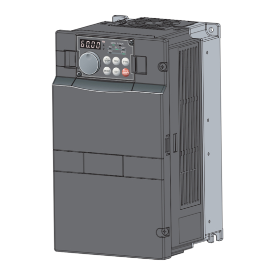
Product checking and parts identification 1 OUTLINE 1.1 Product checking and parts identification Unpack the inverter and check the capacity plate on the front cover and the rating plate on the inverter side face to ensure that the product agrees with your order and the inverter is intact. •... -
Page 9: Step Of Operation
Step of operation 1.2 Step of operation The inverter needs frequency command and start command. Frequency command (set frequency) determines the rotation speed of the motor. Turning ON the start command starts the motor to rotate. Refer to the flow chart below to perform setting. Step of operation Step of operation f op... -
Page 10: Installation And Wiring
2 INSTALLATION AND WIRING (Refer to page 27) USB connector Three-phase AC power supply A personal computer and an inverter can Use within the permissible power supply be connected with a USB (Ver1. 1) cable. specifications of the inverter. (Refer to page 171) Inverter (FR-A700) Moulded case circuit breaker (MCCB) or The life of the inverter is influenced by... -
Page 11: Peripheral Devices
Motor Output (NF or NV type) Applicable Inverter Model (kW) Power factor improving Power factor improving (AC or DC) reactor (AC or DC) reactor without with without with FR-A720-0.4K S-N10 S-N10 0.75 FR-A720-0.75K S-N10 S-N10 FR-A720-1.5K S-N10 S-N10 FR-A720-2.2K S-N10 S-N10 FR-A720-3.7K... - Page 12 Peripheral devices 400V class Moulded Case Circuit Breaker (MCCB) or Earth Leakage Input Side Magnetic Contactor Circuit Breaker (ELB) Motor Output (NF or NV type) Applicable Inverter Model (kW) Power factor improving Power factor improving (AC or DC) reactor (AC or DC) reactor without with without...
-
Page 13: Method Of Removal And Reinstallation Of The
When reinstalling the operation panel, insert it straight to reinstall securely and tighten the fixed screws of the operation panel. FR-A720-0.4K to 22K, FR-A740-0.4K to 22K • Removal 1) Loosen the installation screws of the 2) Pull the front cover toward you to remove by pushing an front cover. - Page 14 Method of removal and reinstallation of the front cover FR-A720-30K or higher, FR-A740-30K or higher • Removal 1) Remove installation screws on 2) Loosen the installation 3) Pull the front cover 2 toward you to remove the front cover 1 to remove the screws of the front cover 2.
-
Page 15: Installation Of The Inverter And Instructions
Installation of the inverter and instructions 2.3 Installation of the inverter and instructions • Installation of the Inverter Installation on the enclosure CAUTION 0.4K to 22K 30K or higher ⋅ When encasing multiple inverters, install them in parallel as a cooling measure. ⋅... -
Page 16: Wiring
ON/OFF Jumper S1/L21 connecter Earth (Ground) *2. To supply power to the Main circuit *9.The FR-A720-0.4K and 0.75K control circuit separately, are not provided with the EMC remove the jumper across Earth filter ON/OFF connector. (Always on) Control circuit R1/L11 and S1/L21. -
Page 17: Emc Filter
ON/OFF connector The FR-A720-0.4K and 0.75K are not provided with the EMC filter ON/OFF connector. (The EMC filter is always valid.) <How to disconnect the connector> (1) Before removing a front cover, check to make sure that the indication of the inverter operation panel is OFF, wait for at least 10 minutes after the power supply has been switched OFF, and check that there are no residual voltage using a tester or the like. -
Page 18: Specification Of Main Circuit Terminal
· When connecting a dedicated brake resistor (FR-ABR) and brake unit (FR-BU2, FR-BU, BU) remove jumpers across terminals PR-PX (7.5K or lower). For details, refer to page 35. 2.4.4 Terminal arrangement of the main circuit terminal, power supply and the motor wiring. FR-A720-0.4K, 0.75K FR-A720-1.5K to 3.7K FR-A740-0.4K to 3.7K Jumper Jumper... - Page 19 Wiring FR-A720-5.5K, 7.5K FR-A720-11K FR-A740-5.5K, 7.5K FR-A740-11K, 15K R1/L11 S1/L21 Charge lamp Jumper Charge lamp Jumper P/+ PR Jumper Jumper R1/L11 S1/L21 R/L1 S/L2 T/L3 R/L1 S/L2 T/L3 Power supply Motor Power supply Motor FR-A720-15K to 22K FR-A720-30K to 45K FR-A740-18.5K, 22K FR-A740-30K to 45K R1/L11 S1/L21...
- Page 20 Wiring FR-A740-75K, 90K FR-A720-75K, 90K FR-A740-110K to 185K R1/L11 S1/L21 R1/L11 S1/L21 Charge lamp Charge lamp Jumper Jumper R/L1 S/L2 T/L3 N/- R/L1 S/L2 T/L3 Power Motor supply DC reactor Motor For option DC reactor FR-A740-220K to 500K R1/L11 S1/L21 Charge lamp Jumper R/L1 S/L2 T/L3 N/-...
- Page 21 U, V, W U, V, W P/+, P1 U, V, W U, V, W S/L2, S/L2, S/L2, S/L2, cable cable T/L3 T/L3 T/L3 T/L3 FR-A720-0.4K to 2.2K FR-A720-3.7K 5.5-4 5.5-4 FR-A720-5.5K M5(M4) 5.5-5 5.5-5 FR-A720-7.5K M5(M4) 14-5 FR-A720-11K 14-5 14-5...
- Page 22 Wiring For the FR-A740-55K or higher, the recommended cable size is that of the cable (THHN cable) with continuous maximum permissible temperature of 90°C. Assumes that the surrounding air temperature is 40°C or less and wiring is performed in an enclosure. (Selection example for use mainly in the United States.) For the FR-A720-15K or lower, and FR-A740-45K or lower, the recommended cable size is that of the cable (PVC cable) with continuous maximum permissible temperature of 70°C.
- Page 23 Wiring (3) Total wiring length The overall wiring length for connection of a single motor or multiple motors should be within the value in the table below. (The wiring length should be 100m maximum for vector control.) Pr. 72 setting 0.4K 0.75K 1.5K or higher...
- Page 24 Do not connect the power cable to incorrect terminals. Doing so may R1/L11 damage the inverter. S1/L21 Remove the jumper • FR-A720-0.4K to 3.7K, FR-A740-0.4K to 3.7K 1) Loosen the upper screws. 2) Remove the lower screws. 3) Remove the jumper 4) Connect the separate power...
- Page 25 Wiring • FR-A720-11K or higher, FR-A740-11K or higher 1) Remove the upper screws. 2) Remove the lower screws. L21 Power supply 3) Pull the jumper toward you to terminal block remove. for the control circuit Power supply terminal block 4) Connect the separate power supply for the control circuit R/L1S/L2 T/L3 cable for the control circuit to the...
-
Page 26: Control Circuit Terminals
Wiring 2.4.5 Control circuit terminals indicates that terminal functions can be selected using Pr. 178 to Pr. 196 (I/O terminal function selection) (Refer to Chapter 4 of the Instruction Manual (Applied).) (1) Input signals Terminal Terminal Rated Refer to Description Symbol Name Specifications... - Page 27 Wiring Terminal Terminal Rated Refer to Description Symbol Name Specifications page External Connect this terminal to the power supply common terminal of a transistor transistor output (open collector output) device, such as a common programmable controller, in the sink logic to avoid malfunction by Power supply (sink) undesirable currents.
- Page 28 Wiring Terminal Terminal Rated Refer to Description Symbol Name Specifications page Switched low when the inverter output frequency is equal to or Inverter higher than the starting frequency (initial value 0.5Hz). Switched running high during stop or DC injection brake operation. Switched low when the output Permissible load frequency reaches within the range of...
-
Page 29: Changing The Control Logic
Wiring 2.4.6 Changing the control logic The input signals are set to sink logic (SINK) when shipped from the factory. To change the control logic, the jumper connector on the back of the control circuit terminal block must be moved to the other position. - Page 30 Wiring 4) Sink logic and source logic ⋅ In sink logic, a signal switches ON when a current flows from the corresponding signal input terminal. Terminal SD is common to the contact input signals. Terminal SE is common to the open collector output signals. ⋅...
-
Page 31: Wiring Of Control Circuit
Wiring 2.4.7 Wiring of control circuit (1) Control circuit terminal layout Control circuit terminal * C2 10E 10 Terminal screw size: M3.5 Tightening torque: 1.2N·m * Refer to instruction manuals of STOP options for the available control terminals other than the standard control circuit terminal. -
Page 32: Mounting The Operation Panel (Fr-Du07) On The Enclosure Surface
Wiring Wiring of the control circuit of the 75K or higher For wiring of the control circuit of the 75K or higher, separate away from wiring of the main circuit. Make cuts in rubber bush of the inverter side and lead wires. <Wiring>... -
Page 33: Terminal Block
Wiring 2.4.10 RS-485 terminal block ⋅ Conforming standard: EIA-485(RS-485) OPEN ⋅ Transmission format: Multidrop link ⋅ Communication speed: MAX 38400bps ⋅ Overall length: 500m Terminating resistor switch ⋅ Connection cable:Twisted pair cable Factory-set to "OPEN". Set only the terminating resistor switch of (4 pairs) 100Ω... -
Page 34: Usb Connector
Wiring 2.4.12 USB connector A personal computer and an inverter can be connected with a USB (Ver1. 1) cable. You can perform parameter setting and monitoring with the FR Configurator. • USB communication specifications Interface Conforms to USB1.1 Transmission speed 12Mbps Wiring length Maximum 5m... -
Page 35: Connection Of Motor With Encoder (Vector Control)
Wiring 2.4.13 Connection of motor with encoder (vector control) Orientation control and encoder feedback control, and speed control, torque control and position control by full-scale vector control operation can be performed using a motor with encoder and a plug-in option FR-A7AP. (1) Structure of the FR-A7AP Mounting Front view... - Page 36 Wiring (3) Switches of the FR-A7AP • Encoder specification selection switch (SW1) Differential line Select either differential line driver or complementary driver (initial status) It is initially set to the differential line driver. Switch its position according to output circuit. Complementary •...
- Page 37 Wiring (4) Encoder Cable SF-JR Motor with Encoder SF-V5RU, SF-THY Inverter side Encoder side MS3057-12A F-DPEVSB 12P 0.2mm MS3057-12A connector Approx. 140mm F-DPEVSB 12P 0.2mm Earth cable Earth cable 60mm 60mm MS3106B20-29S MS3106B20-29S Type Length L (m) ⋅ A P clip for earthing (grounding) a Type Length L (m) shielded cable is provided.
-
Page 38: Speed Control
Wiring Connection terminal compatibility table Motor SF-V5RU, SF-THY SF-JR/HR/JRCA/HRCA (with Encoder) Encoder cable FR-V7CBL FR-JCBL Keep this open. Keep this open. FR-A7AP terminal Keep this open. (5) Wiring • Speed control Vector control dedicated motor Standard motor with encoder (SF-JR), 5V differential line driver (SF-V5RU, SF-THY), 12V complementary MCCB... -
Page 39: Position Control
Wiring • Position control Vector control dedicated motor (SF-V5RU, SF-THY), 12V complementary MCCB SF-V5RU, SF-THY Three-phase AC power supply MCCB Positioning unit Three-phase R/L1 MELSEQ-Q QD75P1 Inverter AC power S/L2 supply T/L3 Earth Thermal (ground) External thermal protector 2W1kΩ STOP CS(OH) relay input *8 Forward stroke end... -
Page 40: Initial Setting
Wiring (6) Instructions for encoder cable wiring Example of parallel connection • Use twisted pair shield cables (0.2mm or larger) to connect the FR-A7AP and with two cables position detector. Cables to terminals PG and SD should be connected in (with complementary encoder output) parallel or be larger in size according to the cable length. - Page 41 Wiring (9) Combination with a vector control dedicated motor Refer to the table below when using with a vector control dedicated motor. • Combination with the SF-V5RU and SF-THY Voltage 200V class 400V class Rated speed 1500r/min Base frequency 50Hz Maximum speed 3000r/min Motor frame...
-
Page 42: Connection Of Stand-Alone Option Units
Set parameters below. ⋅ Pr. 30 Regenerative function selection = "1" ⋅ Pr. 70 Special regenerative brake duty = "7.5K or lower: 10%, 11K or higher: 6%" FR-A720-0.4K to 0.75K FR-A720-1.5 to 3.7K, FR-A740-0.4K to 3.7K 1) Remove the screws in terminals... - Page 43 Connection of stand-alone option units FR-A720-11K, FR-A740-11K, 15K FR-A720-15K to 22K, FR-A740-18.5K, 22K Connect the brake resistor Connect the brake resistor across terminals P/+ and PR. across terminals P/+ and PR. Jumper * Terminal PR Terminal P/+ Terminal PR Terminal P/+ Jumper Brake resistor Brake resistor...
-
Page 44: Connection Of The Brake Unit (Fr-Bu2)
Connection of stand-alone option units 2.5.2 Connection of the brake unit (FR-BU2) Connect the brake unit (FR-BU2) as shown below to improve the braking capability at deceleration. (1) Connection example with the GRZG type discharging resistor OCR contact GRZG type discharging resistor MCCB External thermal... - Page 45 Connection of stand-alone option units (2) FR-BR-(H) connection example with resistor unit FR-BR MCCB Motor R/L1 Three phase AC S/L2 power supply T/L3 FR-BU2 Inverter 5m or less Connect the inverter terminals (P/+, N/-) and brake unit (FR-BU2) terminals so that their terminal names match with each other. (Incorrect connection will damage the inverter and brake unit.) When the power supply is 400V class, install a step-down transformer.
-
Page 46: Connection Of The Brake Unit (Fr-Bu/Mt-Bu5)
Connection of stand-alone option units 2.5.3 Connection of the brake unit (FR-BU/MT-BU5) When connecting the brake unit (FR-BU(H)/MT-BU5) to improve the brake capability at deceleration, make connection as shown below. (1) Connection with the FR-BU (55K or lower) FR-BR MCCB Motor R/L1 Three-phase AC... - Page 47 Connection of stand-alone option units (2) Connection with the MT-BU5 (75K or higher) After making sure that the MT-BU5 is properly connected, set the following parameters. Pr. 30 Regenerative function selection = "1" Pr. 70 Special regenerative brake duty = "10%" MCCB Motor R/L1...
-
Page 48: Connection Of The Brake Unit (Bu Type)
Connection of stand-alone option units 2.5.4 Connection of the brake unit (BU type) Connect the brake unit (BU type) correctly as shown below. Incorrect connection will damage the inverter. Remove the jumper across terminals HB-PC and terminals TB-HC of the brake unit and fit it to across terminals PC-TB. Inverter MCCB Motor... - Page 49 Connection of stand-alone option units (2) Connection with the MT-HC (75K or higher) After making sure the wiring is correct, set the following parameters. Pr. 19 Base frequency voltage (under V/F control) or Pr. 83 Rated motor voltage (under a control method other than V/F control) = "rated motor voltage"...
-
Page 50: Connection Of The Power Regeneration Common Converter (Fr-Cv)
Connection of stand-alone option units 2.5.6 Connection of the power regeneration common converter (FR-CV) When connecting the power regeneration common converter (FR-CV), make connection so that the inverter terminals (P/+, N/-) and the terminal symbols of the power regeneration common converter (FR-CV) are the same (55K or lower). After making sure that the wiring is correct, set "2"... -
Page 51: Connection Of Power Regeneration Converter (Mt-Rc)
Connection of stand-alone option units 2.5.7 Connection of power regeneration converter (MT-RC) When connecting a power regeneration converter (MT-RC), perform wiring securely as shown below. Incorrect connection will damage the regeneration converter and inverter. After connecting securely, set "1" in Pr. 30 Regenerative function selection and "0"... -
Page 52: Power-Off And Magnetic Contactor (Mc)
Power-off and magnetic contactor (MC) 2.6 Power-off and magnetic contactor (MC) (1) Inverter input side magnetic contactor (MC) On the inverter input side, it is recommended to provide an MC for the following purposes. Refer to page 4 for selection.) 1) To release the inverter from the power supply when a fault occurs or when the drive is not functioning (e.g. -
Page 53: Precautions For Use Of The Inverter
Precautions for use of the inverter 2.7 Precautions for use of the inverter The FR-A700 series is a highly reliable product, but incorrect peripheral circuit making or operation/handling method may shorten the product life or damage the product. Before starting operation, always recheck the following items. (1) Use crimping terminals with insulation sleeve to wire the power supply and motor. - Page 54 Precautions for use of the inverter (13) Provide electrical and mechanical interlocks for MC1 and MC2 which are used for bypass operation. Interlock When the wiring is incorrect or if there is an electronic bypass Power R/L1 circuit as shown on the right, the inverter will be damaged by supply S/L2 leakage current from the power supply is connected to the...
-
Page 55: Failsafe Of The System Which Uses The Inverter
Failsafe of the system which uses the inverter 2.8 Failsafe of the system which uses the inverter When a fault occurs, the inverter trips to output a fault signal. However, a fault output signal may not be output at an inverter fault occurrence when the detection circuit or output circuit fails, etc. -
Page 56: Driving The Motor
Operation panel (FR-DU07) 3 DRIVING THE MOTOR 3.1 Operation panel (FR-DU07) 3.1.1 Parts of the operation panel (FR-DU07) Operation mode indicator PU: Lit to indicate PU operation mode. EXT: Lit to indicate External operation mode. NET: Lit to indicate Network operation mode. Rotation direction indicator FWD: Lit when forward rotation REV: Lit when reverse rotation... -
Page 57: Basic Operation (Factory Setting)
Operation panel (FR-DU07) 3.1.2 Basic operation (factory setting) Operation mode switchover At power-ON (External operation mode) PU Jog operation mode (Refer to page 53) (Example) Value change and frequency flicker. PU operation mode Frequency setting has been (output frequency monitor) written and completed!! Output current monitor Output voltage monitor... -
Page 58: Operation Lock (Press [Mode] For An Extended Time (2S))
Operation panel (FR-DU07) 3.1.3 Operation lock (Press [MODE] for an extended time (2s)) Operation using the setting dial and key of the operation panel can be set invalid to prevent parameter change, and unexpected start or frequency setting. · Set "10 or 11" in Pr. 161, then press for 2s to make the setting dial and key operation invalid. -
Page 59: Monitoring Of Output Current And Output Voltage
Operation panel (FR-DU07) 3.1.4 Monitoring of output current and output voltage POINT Monitor display of output frequency, output current and output voltage can be changed by pushing during monitoring mode. Operation [Hz] indicator is lit. Press during operation to choose the output frequency monitor. Independently of whether the inverter is running in any operation mode or at a stop, the output current monitor appears by pressing . -
Page 60: Changing The Parameter Setting Value
Operation panel (FR-DU07) 3.1.7 Changing the parameter setting value Changing example Change the Pr. 1 Maximum frequency . Operation Screen at power-ON The monitor display appears. Operation mode change Press to choose the PU operation mode. [PU] indicator is lit. Parameter setting mode Press to choose the parameter setting mode. -
Page 61: Parameter Clear, All Parameter Clear
Operation panel (FR-DU07) 3.1.8 Parameter clear, all parameter clear POINT · Set "1" in Pr. CL parameter clear or ALLC All parameter clear to initialize all parameters. (Parameters are not cleared when "1" is set in Pr. 77 Parameter write selection. Calibration parameters are not cleared with Pr.CL either.) ·... -
Page 62: Parameter Copy And Parameter Verification
Operation panel (FR-DU07) 3.1.9 Parameter copy and parameter verification PCPY Setting Description Cancel Copy the source parameters to the operation panel. Write the parameters copied to the operation panel into the destination inverter. Verify parameters in the inverter and operation panel. (Refer to page 56.) REMARKS ·... - Page 63 Operation panel (FR-DU07) (2) Parameter verification Whether same parameter values are set in other inverters or not can be checked. Operation Move the operation panel to the inverter to be verified. Move it during a stop. Screen at power-ON The monitor display appears. Parameter setting mode Press to choose the parameter setting mode.
-
Page 64: Before Operation
Before operation 3.2 Before operation 3.2.1 Simple mode parameter list For simple variable-speed operation of the inverter, the initial setting of the parameters may be used as they are. Set the necessary parameters to meet the load and operational specifications. Parameter setting, change and check can be made from the operation panel (FR-DU07). -
Page 65: Overheat Protection Of The Motor By The Inverter (Pr. 9)
Before operation 3.2.2 Overheat protection of the motor by the inverter (Pr. 9) Set the rated motor current in Pr. 9 Electronic thermal O/L relay to protect the motor from overheat. Refer to page 53 for how to change the parameter setting. Parameter Name Initial Value... -
Page 66: Increasing The Starting Torque (Pr. 0)
Before operation 3.2.4 Increasing the starting torque (Pr. 0) Set this parameter when "the motor with a load will not rotate", "an alarm [OL] is output, resulting in an inverter trip due to [OC1], etc. 100% When the motor with a load will not rotate, increase the Pr. 0 value 1% by 1% unit by looking at the motor movement. -
Page 67: Changing Acceleration And Deceleration Time (Pr. 7, Pr. 8)
Before operation 3.2.6 Changing acceleration and deceleration time (Pr. 7, Pr. 8) Set in Pr. 7 Acceleration time a larger value for a slower speed increase and Pr.20 a smaller value for a faster speed increase. (60Hz) Set in Pr. 8 Deceleration time a larger value for a slower speed decrease and Running frequency a smaller value for a faster speed decrease. - Page 68 Before operation (2) Energy saving control (Pr. 60) Without complicated parameter settings, the inverter could automatically perform energy saving control. This inverter is optimal for fan and pump applications. Parameter Setting Name Initial Value Description Number Range Energy saving control Normal operation mode selection * Energy saving operation mode...
-
Page 69: Selection Of The Start Command And Frequency Command Locations (Pr. 79)
Before operation 3.2.8 Selection of the start command and frequency command locations (Pr. 79) Select the start command location and frequency command location. LED Indication Parameter Initial Setting Name Description : Off Number Value Range : On PU operation mode Use External/PU switchover mode (press to switch External operation mode... -
Page 70: Acquiring Large Starting Torque And Low Speed Torque (Advanced Magnetic Flux Vector Control, Real Sensorless Vector Control) (Pr. 71, Pr. 80, Pr. 81, Pr. 800)
Before operation 3.2.9 Acquiring large starting torque and low speed torque (Advanced magnetic flux vector control, Real sensorless vector control) (Pr. 71, Pr. 80, Pr. 81, Pr. 800) Magnetic flux Magnetic flux Magnetic flux Sensorless Sensorless Sensorless Advanced magnetic flux vector control can be selected by setting the capacity, poles and type of the motor used in Pr. 80 and Pr. -
Page 71: Test Run
Before operation <Selection method of Advanced magnetic flux vector control> Perform secure wiring. (Refer to page 9.) Set the motor. (Pr. 71) Motor Pr. 71 Setting Remarks SF-JR 0 (initial value) Mitsubishi standard SF-JR 4P-1.5kW or less motor SF-HR Mitsubishi high Offline auto tuning is efficiency motor Others... - Page 72 Before operation <Selection method of Real sensorless vector control (speed control) > Speed control is exercised to match the speed command and actual motor speed. Perform secure wiring. (Refer to page 9.) Set the motor. (Pr. 71) (Refer to page 63.) Set "3"...
-
Page 73: Higher Accuracy Operation Using A Motor With Encoder (Vector Control) (Pr.71, Pr.80, Pr.81, Pr.359, Pr.369, Pr.800)
Before operation 3.2.10 Higher accuracy operation using a motor with encoder (Vector control) (Pr.71, Pr.80, Pr.81, Pr.359, Pr.369, Pr.800) Vector Vector Vector Full-scale vector control can be performed fitting the FR-A7AP/FR-A7AL and using a motor with encoder. Fast response/high accuracy speed control (zero speed control, servo lock), torque control, and position control can be performed. - Page 74 Before operation POINT If the conditions below are not satisfied, malfunction such as insufficient torque and uneven rotation may occur. The motor capacity should be equal to or one rank lower than the inverter capacity. (note that the capacity is ·...
- Page 75 Before operation <Selection method of speed control> Speed control is exercised to match the speed command and actual motor speed. Perform secure wiring. (Refer to page 31.) Mount the FR-A7AP/FR-A7AL (option). Set the motor and encoder. (Pr. 71, Pr. 359, Pr. 369) Set Pr.
- Page 76 Before operation <Selection method of torque control> Torque control is exercised to develop torque as set in the torque command. The motor speed becomes constant when the motor output torque and load torque are balanced. For torque control, therefore, the speed is determined by the load. For torque control, the motor gains speed as the motor output torque becomes greater than the motor load.
- Page 77 Before operation <Selection method of position control> In the position control, the speed command is calculated so that the difference between command pulse (or parameter setting) and the number of feedback pulses from the encoder is zero in order to run the motor. This inverter can perform simple position feed by contact input, position control by inverter simple pulse input, and position control by FR-A7AL pulse train input.
-
Page 78: Exhibiting The Best Performance Of The Motor Performance (Offline Auto Tuning) (Pr. 71, Pr. 83, Pr. 84, Pr. 96)
Before operation 3.2.11 Exhibiting the best performance of the motor performance (offline auto tuning) (Pr. 71, Pr. 83, Pr. 84, Pr. 96) Magnetic flux Magnetic flux Magnetic flux Sensorless Sensorless Sensorless Vector Vector Vector The motor performance can be maximized with offline auto tuning. •... - Page 79 Before operation (2) Setting 1) Select the Advanced magnetic flux vector control, Real sensorless vector control or vector control. 2) Set "1" or "101" in Pr. 96 Auto tuning setting/status . When the setting is "1" ..Tuning is performed without motor running. ·...
- Page 80 Before operation (3) Execution of tuning CAUTION · Before performing tuning, check the monitor display of the operation panel (FR-DU07) or parameter unit (FR-PU04/FR- PU07) if the inverter is in the state ready for tuning. (Refer to 2) below) When the start command is turned ON under V/F control, the motor starts.
- Page 81 Before operation 3)When offline auto tuning ends, press of the operation panel during PU operation. For External operation, turn OFF the start signal (STF signal or STR signal). This operation resets the offline auto tuning and the PU's monitor display returns to the normal indication. (Without this operation, next operation cannot be started.) REMARKS ·...
-
Page 82: High Accuracy Operation Unaffected By The Motor Temperature (Online Auto Tuning) (Pr. 95)
Before operation 3.2.12 High accuracy operation unaffected by the motor temperature (online auto tuning) (Pr. 95) Magnetic flux Magnetic flux Magnetic flux Sensorless Sensorless Sensorless Vector Vector Vector When online auto tuning is selected under Advanced magnetic flux vector control, Real sensorless vector control or vector control, excellent torque accuracy is provided by temperature compensation even if the secondary resistance value of the motor varies with the rise of the motor temperature. -
Page 83: To Perform High Accuracy/Fast Response Operation (Gain Adjustment Of Real Sensorless Vector Control And Vector Control) (Pr. 818 To Pr. 821, Pr. 880)
Before operation 3.2.13 To perform high accuracy/fast response operation (gain adjustment of Real sensorless vector control and vector control) (Pr. 818 to Pr. 821, Pr. 880) Sensorless Sensorless Sensorless Vector Vector Vector The ratio of the load inertia to the motor inertia (load inertia moment) is estimated in real time from the torque command and speed during motor operation by vector control. - Page 84 Before operation 2) Each control gain is automatically set from the load inertia ratio estimated during acceleration/deceleration operation and the Pr. 818 Easy gain tuning response level setting value. Pr. 880 Load inertia ratio is used as the initial value of the load inertia ratio for tuning. Estimated value is set in Pr. 880 during tuning.
- Page 85 Before operation (4) Manual input speed control gain adjustment · Make adjustment when any of such phenomena as unusual machine vibration/noise, low response level and overshoot has occurred. Proportional gain · Pr. 820 Speed control P gain 1 = "60%" (initial value) is equivalent to 120rad/s (speed response of the motor alone).
- Page 86 Before operation (5) When using a multi-pole motor (8 poles or more) Specially when using a multi-pole motor with more than 8 poles under Real sensorless vector control or vector control, adjust Pr. 820 Speed control P gain 1 and Pr. 824 Torque control P gain 1 according to the motor referring to the following methods.
- Page 87 Before operation (6) Troubleshooting (speed) Phenomenon Cause Countermeasures (1) The motor wiring is wrong (1) Wiring check Select V/F control (set "9999" in Pr. 80 or Pr. 81 ) and check the rotation direction of the motor. For the SF-V5RU (1500r/min series), set "170V(340V)"...
- Page 88 Before operation Phenomenon Cause Countermeasures (1) The speed command varies. (1) -1 Check that a correct speed command comes from the command device. (Take measures against noises.) (1) -2 Decrease Pr. 72 PWM frequency selection. (1) -3 Increase Pr. 822 Speed setting filter 1. (Refer to Chapter 4 of the Instruction Manual (Applied) ) Motor speed is unstable.
-
Page 89: Start/Stop Using The Operation Panel (Pu Operation)
Start/stop using the operation panel (PU operation) 3.3 Start/stop using the operation panel (PU operation) POINT From where is the frequency command given? · Operation at the frequency set in the frequency setting mode of the operation panel →Refer to 3.3.1 (Refer to page 82) ·... -
Page 90: Using The Setting Dial Like A Potentiometer To Perform Operation
Start/stop using the operation panel (PU operation) 3.3.2 Using the setting dial like a potentiometer to perform operation. POINT Set "1" (setting dial potentiometer mode) in Pr. 161 Frequency setting/key lock operation selection. Operation example Change the frequency from 0Hz to 60Hz during operation Operation Screen at power-ON The monitor display appears. -
Page 91: Setting The Frequency By Switches (Multi-Speed Setting)
Start/stop using the operation panel (PU operation) 3.3.3 Setting the frequency by switches (multi-speed setting) POINT · Use on the operation panel (FR-DU07) to give a start command. · Switch ON the RH, RM, or RL signal to give a frequency command. (Multi-speed setting) ·... -
Page 92: Setting The Frequency By Analog Input (Voltage Input)
Start/stop using the operation panel (PU operation) 3.3.4 Setting the frequency by analog input (voltage input) POINT · Use on the operation panel (FR-DU07) to give a start command. · Use the potentiometer to give a frequency command. (by connecting terminal 2 and 5 (voltage input)) ·... -
Page 93: Setting The Frequency By Analog Input (Current Input)
Start/stop using the operation panel (PU operation) 3.3.5 Setting the frequency by analog input (current input) POINT · Use on the operation panel (FR-DU07) to give a start command. · Use the current signal source (4 to 20mA) to give a frequency command (by connecting between terminals 4 and 5 (current input)). -
Page 94: Start And Stop Using Terminals (External Operation)
Start and stop using terminals (External operation) 3.4 Start and stop using terminals (External operation) POINT From where is the frequency command given? · Operation at the frequency set in the frequency setting mode of the operation panel → Refer to 3.4.1 (Refer to page 87) ·... -
Page 95: Setting The Frequency By Switches (Multi-Speed Setting) (Pr. 4 To Pr. 6)
Start and stop using terminals (External operation) 3.4.2 Setting the frequency by switches (multi-speed setting) (Pr. 4 to Pr. 6) POINT · Switch ON the STF (STR) signal to give a start command. · Switch ON the RH, RM, or RL signal to give a frequency command. (Multi-speed setting) [Connection diagram] Speed 1 Inverter... -
Page 96: Setting The Frequency By Analog Input (Voltage Input)
Start and stop using terminals (External operation) 3.4.3 Setting the frequency by analog input (voltage input) POINT · Switch ON the STF (STR) signal to give a start command. · Use the potentiometer (by connecting terminal 2 and 5 (voltage input)) to give a frequency command. [Connection diagram] (The inverter supplies 5V of power to frequency setting potentiometer. -
Page 97: Changing The Output Frequency (60Hz, Initial Value) At The Maximum Voltage Input (5V, Initial Value)
Start and stop using terminals (External operation) 3.4.4 Changing the output frequency (60Hz, initial value) at the maximum voltage input (5V, initial value) <How to change the maximum frequency> Changing example When you use the 0 to 5VDC input and want to change the frequency at 5V from 60Hz (initial value) to 50Hz, set "50Hz"... -
Page 98: Setting The Frequency By Analog Input (Current Input)
Start and stop using terminals (External operation) 3.4.5 Setting the frequency by analog input (current input) POINT · Switch ON the STF (STR) signal to give a start command. · Turn the AU signal ON. · Set "2" (External operation mode) in Pr. 79 Operation mode selection. [Connection diagram] Inverter Forward rotation start... -
Page 99: Changing The Output Frequency (60Hz, Initial Value) At The Maximum Current Input (At 20Ma, Initial Value)
Start and stop using terminals (External operation) 3.4.6 Changing the output frequency (60Hz, initial value) at the maximum current input (at 20mA, initial value) <How to change the maximum frequency?> Changing example When you use the 4 to 20mA input and want to change the frequency at 20mA from 60Hz (initial value) to 50Hz, set "50Hz"... -
Page 100: Parameter List
Parameter List 3.5 Parameter List 3.5.1 List of parameters classified by the purpose Set the parameters according to the operating conditions. The following list indicates purpose of use and corresponding parameters. Purpose of Use Parameter Number Control mode Change the control method Pr. - Page 101 Parameter List Purpose of Use Parameter Number Pr. 7, Pr. 8, Pr. 20, Pr. 21, Pr. 44, Acceleration/deceleration time setting Pr. 45, Pr. 110, Pr. 111 Starting frequency Pr. 13, Pr. 571 Pr. 29, Pr. 140 to Pr. 143, Pr.380 to Acceleration/deceleration Acceleration/deceleration pattern and backlash measures Pr.
- Page 102 Parameter List Purpose of Use Parameter Number Energy saving control selection Pr. 60 Energy saving operation How much energy can be saved (energy saving monitor) Pr. 891 to Pr. 899 Carrier frequency and SoftPWM selection Pr. 72, Pr. 240 Reduction of the motor noise Measures against noise and Pr.
-
Page 103: Parameter List
Parameter List 3.5.2 Parameter list · indicates simple mode parameters. · " " indicates enabled and "×" indicates disabled of "parameter copy", "parameter clear", and "all parameter clear". · " *" indicates a communication parameter which is not cleared by parameter clear (all clear) from the RS-485 communication. - Page 104 Parameter List Parameter Incre- Initial Name Range Description ments Value : enabled × : disabled Set the motor acceleration time. 0.1/ 0 to 3600/ Acceleration time 5/15s * The initial value differs according to the 0.01s 360s inverter capacity. (7.5K or lower/11K or higher) Set the motor deceleration time.
- Page 105 Parameter List Parameter Incre- Initial Name Range Description ments Value : enabled × : disabled Starting frequency 0.01Hz 0.5Hz 0 to 60Hz Starting frequency can be set. Set the holding time of Pr. 13 Starting 0.0 to 10.0s frequency. Holding time at a 0.1s 9999 start...
- Page 106 Parameter List Parameter Incre- Initial Name Range Description ments Value : enabled × : disabled Stall prevention operation selection becomes invalid. Function as stall prevention operation Stall prevention under V/F control and Advanced magnetic 0.1% 150% operation level flux vector control. 0.1 to 400% Set the current value at which stall prevention operation is started.
- Page 107 Parameter List Parameter Incre- Initial Name Range Description ments Value : enabled × : disabled This functions as torque limit level under Real sensorless vector control. * For the 3.7K or lower, the initial value changes from 150% to 200% when V/F control or 150/ Torque limit level 0.1%...
- Page 108 Parameter List Parameter Incre- Initial Name Range Description ments Value : enabled × : disabled Linear acceleration/ deceleration S-pattern acceleration/deceleration A Acceleration/ S-pattern acceleration/deceleration B deceleration pattern Backlash measures selection S-pattern acceleration/deceleration C S-pattern acceleration/deceleration D Backlash acceleration 0.01Hz 0 to 400Hz stopping frequency Backlash acceleration 0.1s...
- Page 109 Parameter List Parameter Incre- Initial Name Range Description ments Value : enabled × : disabled 0 to 400Hz, Frequency jump 1A 0.01Hz 9999 9999 0 to 400Hz, Frequency jump 1B 0.01Hz 9999 9999 0 to 400Hz, Frequency jump 2A 0.01Hz 9999 1A to 1B, 2A to 2B, 3A to 3B is frequency 9999...
- Page 110 Parameter List Parameter Incre- Initial Name Range Description ments Value : enabled × : disabled 0, 5 to 14, Select monitor to be displayed on the operation panel and parameter unit and monitor to be 17 to 20, output to the terminal FM and AM. DU/PU main display 22 to 25, 0 : Output frequency (Pr.
- Page 111 Parameter List Parameter Incre- Initial Name Range Description ments Value : enabled × : disabled Set the full-scale value to output the output Frequency 0.01Hz 60Hz 0 to 400Hz frequency monitor value to terminal FM monitoring reference and AM. Set the full-scale value to output the output Inverter current monitor value to terminal FM and AM.
- Page 112 Parameter List Parameter Incre- Initial Name Range Description ments Value : enabled × : disabled Setting value (rated motor current) is referenced 0 to 500/ * The increments and setting range differ 0.01/ Reference current 9999 0 to 3600A* according to the inverter capacity. (55K or 0.1A* lower/75k or higher) 9999...
- Page 113 Parameter List Parameter Incre- Initial Name Range Description ments Value : enabled × : disabled Thermal characteristics of a standard motor Thermal characteristics of the Mitsubishi constant-torque motor Thermal characteristic of standard motor Adjustable 5 points V/F Mitsubishi standard motor (SF-JR 4P 1.5kW or less) Thermal characteristics of the Mitsubishi vector motor SF-V5RU (1500r/min series)
- Page 114 Parameter List Parameter Incre- Initial Name Range Description ments Value : enabled × : disabled PWM carrier frequency can be changed. The setting displayed is in [kHz]. Note that 0 indicates 0.7kHz, 15 indicates 14.5kHz, 25 indicates 2.5. (25 is exclusively for a sine wave filter.) PWM frequency 0 to 15/...
- Page 115 Parameter List Parameter Incre- Initial Name Range Description ments Value : enabled × : disabled You can select the reset input acceptance, disconnected PU (FR-DU07 /FR-PU07 /FR- Reset selection/ PU04) connector detection function and PU disconnected PU 0 to 3, ×...
- Page 116 Parameter List Parameter Incre- Initial Name Range Description ments Value : enabled × : disabled Set the applied motor capacity. 0.4 to 55/ * The increments and setting range differ 0.01/ Motor capacity 9999 0 to 3600kW according to the inverter capacity. (55K or 0.1kW lower/75k or higher) 9999...
- Page 117 Parameter List Parameter Incre- Initial Name Range Description ments Value : enabled × : disabled Tuning data (The value measured by offline auto tuning 0 to 500/ is automatically set.) Motor excitation 0.01/ * The increments and setting range differ 0 to 3600A * ×...
- Page 118 Parameter List Parameter Incre- Initial Name Range Description ments Value : enabled × : disabled Tuning data of the second motor (The value measured by offline auto tuning 0 to 50Ω/ is automatically set.) Second motor 0.001Ω/ 0 to 400mΩ * * The increments and setting range differ ×...
- Page 119 Parameter List Parameter Incre- Initial Name Range Description ments Value : enabled × : disabled Online auto tuning is not performed Online auto tuning Start-time tuning (at start-up) selection Magnetic flux observer (normal) Second motor Select the second motor online auto 0, 1 online auto tuning tuning.
- Page 120 Parameter List Parameter Incre- Initial Name Range Description ments Value : enabled × : disabled Specify the inverter station number. PU communication Set the inverter station numbers when two 0 to 31 station number or more inverters are connected to one personal computer.
- Page 121 Parameter List Parameter Incre- Initial Name Range Description ments Value : enabled × : disabled PID control Set the frequency at which the control is 0 to 400Hz automatically changed to PID control. automatic 0.01Hz 9999 switchover 9999 Without PID automatic switchover function frequency PID reverse action Deviation value...
- Page 122 Parameter List Parameter Incre- Initial Name Range Description ments Value : enabled × : disabled Electronic bypass Without electronic bypass sequence sequence selection With electronic bypass sequence MC switchover Set the operation interlock time of MC2 0.1s 0 to 100s interlock time and MC3.
- Page 123 Parameter List Parameter Incre- Initial Name Range Description ments Value : enabled × : disabled Output current Set the output current detection level. 0.1% 150% 0 to 220% detection level 100% is the rated inverter current. Set the output current detection period. Output current Set the time from when the output current detection signal...
- Page 124 Parameter List Parameter Incre- Initial Name Range Description ments Value : enabled × : disabled 0 to 20, 0: Low-speed operation command (RL) 22 to 28, 1: Middle-speed operation command STF terminal × 42 to 44, 60, (RM) function selection 62, 64 to 71, 2: High-speed operation command (RH) 74, 9999...
- Page 125 Parameter List Parameter Incre- Initial Name Range Description ments Value : enabled × : disabled 0, 100: Inverter running (RUN) 1, 101: Up to frequency (SU) 0 to 8, RUN terminal × 2, 102: Instantaneous power failure/ 10 to 20, function selection undervoltage (IPF) 25 to 28,...
- Page 126 Parameter List Parameter Incre- Initial Name Range Description ments Value : enabled × : disabled 232 to 239 Refer to Pr. 4 to Pr. 6. Refer to Pr. 72. — Refer to Pr. 125 and Pr. 126. 242, 243 Refer to Pr. 73. Operates at power on Cooling fan on/off control invalid (The cooling fan is always on at power on)
- Page 127 Parameter List Parameter Incre- Initial Name Range Description ments Value : enabled × : disabled Display whether the control circuit capacitor, main circuit capacitor, cooling Life alarm status × × × (0 to 15) fan, and each parts of the inrush current display limit circuit has reached the life alarm output level or not.
- Page 128 Parameter List Parameter Incre- Initial Name Range Description ments Value : enabled × : disabled Refer to Pr. 73. Refer to Pr. 52. — Parameter for manufacturer setting. Do not set. Without stop-on contact control and load torque high-speed frequency control Stop-on contact control Load torque high speed frequency control Stop-on contact/...
- Page 129 Parameter List Parameter Incre- Initial Name Range Description ments Value : enabled × : disabled Set to the rated slip frequency of the motor Brake opening + about 1.0Hz. 0.01Hz 0 to 30Hz This parameter may be only set if Pr. 278 ≤ frequency Pr.
- Page 130 Parameter List Parameter Incre- Initial Name Range Description ments Value : enabled × : disabled Droop control is invalid Set the drooping amount at the rated Droop gain 0.1% 0.1 to torque as a percentage with respect to the 100% rated frequency.
- Page 131 Parameter List Parameter Incre- Initial Name Range Description ments Value : enabled × : disabled Set the inverter station number. RS-485 0 to 31 (same specifications as Pr. 117 ) When "1" communication (Modbus-RTU protocol) is set in Pr. 551, the (0 to 247) station number setting range within parenthesis is applied.
- Page 132 Parameter List Parameter Incre- Initial Name Range Description ments Value : enabled × : disabled Refer to Pr. 79. — 341 to 343 Refer to Pr. 117. Internal stop position command (Pr.356) Stop position External stop position command (FR-A7AX 9999 command selection 16-bit data) 9999...
- Page 133 Parameter List Parameter Incre- Initial Name Range Description ments Value : enabled × : disabled The orientation complete signal (ORA) is output delaying the set time after in- Completion signal 0.1s 0.5s 0 to 5s position zone is entered. Also, the signal output delay time turns off delaying the set time after in- position zone is out.
- Page 134 Parameter List Parameter Incre- Initial Name Range Description ments Value : enabled × : disabled Signal loss detection is invalid Encoder signal loss detection enable/ Signal loss detection is valid disable selection When the cable of the encoder signal is broken during encoder feedback control, orientation control, or vector control, signal loss detection (E.ECT) is activated to stop the...
- Page 135 Parameter List Parameter Incre- Initial Name Range Description ments Value : enabled × : disabled Position Feed Selection Method Speed First position feed 0 to 9999 amount lower 4 digits High speed First position feed (Pr.4) 0 to 9999 amount upper 4 digits Second position feed 0 to 9999 amount lower 4 digits...
- Page 136 Parameter List Parameter Incre- Initial Name Range Description ments Value : enabled × : disabled Remote output data Remote output clear at powering off data is cleared during an inverter Remote output data Remote output held at powering off reset selection Remote output Remote output data...
- Page 137 Parameter List Parameter Incre- Initial Name Range Description ments Value : enabled × : disabled Torque command by terminal 1 analog input Torque command by parameter Pr.805 or Pr.806 setting (-400% to 400%) Torque command using pulse train input Torque command (FR-A7AL) source selection Torque command by using CC-Link (FR-...
- Page 138 Parameter List Parameter Incre- Initial Name Range Description ments Value : enabled × : disabled Set the integral time during speed control. Speed control (Decrease the value to shorten the time 0.001s 0.333s 0 to 20s integral time 1 taken for returning to the original speed if speed variation with disturbance occurs.) Second function of Pr.
- Page 139 Parameter List Parameter Incre- Initial Name Range Description ments Value : enabled × : disabled Refer to Pr. 820. Refer to Pr. 821. Refer to Pr. 74. Refer to Pr. 823. — Refer to Pr. 824. Refer to Pr. 825. Refer to Pr.
- Page 140 Parameter List Parameter Incre- Initial Name Range Description ments Value : enabled × : disabled 859, 860 Refer to Pr. 82. — You can use the machine resonance speed to make this setting to reduce the Notch filter time 0 to 60 response level of the machine resonance constant frequency band, avoiding machine...
- Page 141 Parameter List Parameter Incre- Initial Name Range Description ments Value : enabled × : disabled Regeneration avoidance function invalid Regeneration Regeneration avoidance function is always avoidance valid operation selection Regeneration avoidance function is valid only at constant speed Set the bus voltage level at which regeneration avoidance operates.
- Page 142 Parameter List Parameter Incre- Initial Name Range Description ments Value : enabled × : disabled Set the load factor for commercial power supply operation. Load factor 0.1% 100% 30 to 150% This value is used to calculate the power consumption estimated value during commercial power supply operation.
- Page 143 Parameter List Parameter Incre- Initial Name Range Description ments Value : enabled × : disabled Terminal 1 bias Set the frequency on the bias side of × 0.01Hz 0 to 400Hz (917) frequency (speed) terminal 1 input. (valid when Pr.868 = 5) Set the converted % of the bias side Terminal 1 bias ×...
-
Page 144: Troubleshooting
Reset method of protective function 4 TROUBLESHOOTING When a fault occurs in the inverter, the inverter trips and the PU display automatically changes to one of the following fault or alarm indications. If the fault does not correspond to any of the following faults or if you have any other problem, please contact your sales representative. -
Page 145: List Of Fault Or Alarm Display
List of fault or alarm display 4.2 List of fault or alarm display Operation Panel Refer Operation Panel Refer Name Name Indication Indication Output side earth (ground) E.GF E - - - Faults history fault overcurrent HOLD Operation panel lock E.LF Output phase loss External thermal relay... -
Page 146: Causes And Corrective Actions
Causes and corrective actions 4.3 Causes and corrective actions (1) Error message A message regarding operational troubles is displayed. Output is not shut off. Operation Panel HOLD Indication Name Operation panel lock Description Operation lock mode is set. Operation other than is invalid. - Page 147 Causes and corrective actions Operation Panel Indication Name Mode designation error Appears if a parameter setting is attempted in the External or NET operation mode with Pr. 77 ≠ "2". · Description · Appears if a parameter setting is attempted when the command source is not at the operation panel. (FR- DU07).
- Page 148 Causes and corrective actions (2) Warning When the protective function is activated, the output is not shut off. Operation Panel FR-PU04 Indication FR-PU07 Name Stall prevention (overcurrent) When the output current (output torque during Real sensorless vector control or vector control) of the inverter exceeds the stall prevention operation level (Pr.
- Page 149 Causes and corrective actions Operation Panel FR-PU04 Indication FR-PU07 Name Regenerative brake prealarm Appears if the regenerative brake duty reaches or exceeds 85% of the Pr. 70 Special regenerative brake duty value. When the setting of Pr. 70 Special regenerative brake duty is the initial value (Pr. 70 = "0"), this warning does not occur.
- Page 150 Causes and corrective actions (3) Alarm When an alarm occurs, the output is not shut off. You can also output an alarm signal by making parameter setting. (Set "98" in any of Pr. 190 to Pr. 196 (output terminal function selection). (Refer to Chapter 4 of the Instruction Manual (Applied).)) Operation Panel FR-PU04...
- Page 151 Causes and corrective actions Operation Panel FR-PU04 E.OC3 OC During Dec Indication FR-PU07 Name Overcurrent trip during deceleration or stop When the inverter output current reaches or exceeds approximately 220% of the rated inverter current Description during deceleration (other than acceleration or constant speed), the protective circuit is activated to stop the inverter output.
- Page 152 Causes and corrective actions Operation Panel FR-PU04 E.THT Inv. Ovrload Indication FR-PU07 Name Inverter overload trip (electronic thermal relay function) If a current not less than 150% of the rated output current flows and overcurrent trip does not occur Description (220% or less), the electronic thermal relay activates to stop the inverter output in order to protect the output transistors.
- Page 153 Causes and corrective actions FR-PU04 Operation Panel E.BE Br. Cct. Fault Indication FR-PU07 Name Brake transistor alarm detection This function stops the inverter output if an alarm occurs in the brake circuit, e.g. damaged brake transistors. Description In this case, the inverter must be powered OFF immediately. ·...
- Page 154 Causes and corrective actions FR-PU04 Operation Panel E.LF E.LF Indication FR-PU07 Name Output phase loss This function stops the inverter output if one of the three phases (U, V, W) on the inverter's output side Description (load side) is lost. ·...
- Page 155 Causes and corrective actions Operation Panel FR-PU04 E.OP3 Option3 Fault Indication FR-PU07 Name Communication option fault Description Stops the inverter output when a communication line error occurs in the communication option. · Check for a wrong option function setting and operation. ·...
- Page 156 Causes and corrective actions Operation Panel FR-PU04 E.RET Retry No Over Indication FR-PU07 Name Retry count excess If operation cannot be resumed properly within the number of retries set, this function trips the inverter. Description This function is available only when Pr. 67 Number of retries at fault occurrence is set. When the initial value (Pr.
- Page 157 Causes and corrective actions Operation Panel FR-PU04 E.OSD E.OSd Indication FR-PU07 Name Speed deviation excess detection Trips the inverter if the motor speed is increased or decreased under the influence of the load etc. during vector control with Pr. 285 Excessive speed deviation detection frequency set and cannot be Description controlled in accordance with the speed command value.
- Page 158 Causes and corrective actions Operation Panel FR-PU04 E.P24 E.P24 Indication FR-PU07 Name 24VDC power output short circuit When the 24VDC power output from the PC terminal is shorted, this function shuts off the power output. Description At this time, all external contact inputs switch OFF. The inverter cannot be reset by entering the RES signal.
- Page 159 Causes and corrective actions Operation Panel FR-PU04 E.11 Fault 11 Indication FR-PU07 Name Opposite rotation deceleration fault The speed may not decelerate during low speed operation if the rotation direction of the speed command and the estimated speed differ when the rotation is changing from forward to reverse or from Description reverse to forward during torque control under Real sensorless vector control.
-
Page 160: Correspondences Between Digital And Actual Characters
Correspondences between digital and actual characters 4.4 Correspondences between digital and actual characters There are the following correspondences between the actual alphanumeric characters and the digital characters displayed on the operation panel. Actual Digital Actual Digital Actual Digital... -
Page 161: Check And Clear Of The Faults History
Check and clear of the faults history 4.5 Check and clear of the faults history (1) Check for the faults history Monitor/frequency setting Parameter setting [Operation panel is used [Parameter setting change] for operation] Faults history [Operation for displaying faults history] Eight past faults can be displayed with the setting dial. - Page 162 Check and clear of the faults history (2) Clearing procedure POINT · The faults history can be cleared by setting "1" in Er.CL Faults history clear. Operation Screen at power-ON The monitor display appears. Parameter setting mode Press to choose the parameter setting mode. (The parameter number previously read appears.) Selecting the parameter number Turn...
-
Page 163: Check First When You Have A Trouble
Check first when you have a trouble Check first when you have a trouble Refer to troubleshooting on page 80 (speed control) in addition to the following check points. POINT · If the cause is still unknown after every check, it is recommended to initialize the parameters (initial value) then reset the required parameter values and check again. - Page 164 Check first when you have a trouble Refer Check Possible Cause Countermeasures points page During the External operation mode, check the method of was pressed. restarting from a input stop from PU. (Operation panel indication is (PS).) Check the connection. Two-wire or three-wire type connection is wrong.
-
Page 165: Motor Or Machine Is Making Abnormal Acoustic Noise
Check first when you have a trouble 4.6.2 Motor or machine is making abnormal acoustic noise Even if the carrier frequency (Pr. 72) is set to a value higher than 2kHz for a 55k or lower capacity inverter, the carrier frequency is automatically lowered to as low as 2kHz in an overloaded operation at a low speed (output frequency lower than 3Hz). -
Page 166: Motor Rotates In The Opposite Direction
Check first when you have a trouble 4.6.5 Motor rotates in the opposite direction Refer Check Possible Cause Countermeasures points page Main Phase sequence of output terminals U, V and W is Connect phase sequence of the output cables (terminal Circuit incorrect. -
Page 167: Speed Varies During Operation
Check first when you have a trouble 4.6.8 Speed varies during operation When Advanced magnetic flux vector control, Real sensorless vector control, vector control or encoder feedback control is exercised, the output frequency varies with load fluctuation between 0 and 2Hz. This is a normal operation and is not a fault. Refer Check Possible Cause... -
Page 168: Operation Mode Is Not Changed Properly
Check first when you have a trouble 4.6.9 Operation mode is not changed properly Refer Check Possible Cause Countermeasures points page Check that the STF and STR signals are OFF. Input Start signal (STF or STR) is ON. When either is ON, the operation mode cannot be signal changed. -
Page 169: Speed Does Not Accelerate
Check first when you have a trouble 4.6.12 Speed does not accelerate Refer Check Possible Cause Countermeasures points page Check if the start command and the frequency Start command and frequency command are chattering. — command are correct. Input The wiring length used for analog frequency command Perform analog input bias/gain calibration. -
Page 170: Precautions For Maintenance And Inspection
Inspection item 5 PRECAUTIONS FOR MAINTENANCE AND INSPECTION The inverter is a static unit mainly consisting of semiconductor devices. Daily inspection must be performed to prevent any fault from occurring due to the adverse effects of the operating environment, such as temperature, humidity, dust, dirt and vibration, changes in the parts with time, service life, and other factors. -
Page 171: Daily And Periodic Inspection
Inspection item 5.1.3 Daily and periodic inspection Interval Corrective Action at Inspection Item Description Alarm Occurrence Surrounding Check the surrounding air temperature, humidity, Improve environment environment dirt, corrosive gas, oil mist , etc. Check alarm location and General Overall unit Check for unusual vibration and noise. -
Page 172: Display Of The Life Of The Inverter Parts
Inspection item 5.1.4 Display of the life of the inverter parts The self-diagnostic alarm is output when the life span of the control circuit capacitor, cooling fan, each parts of the inrush current limit circuit is near its end. It gives an indication of replacement time . The life alarm output can be used as a guideline for life judgement. -
Page 173: Cleaning
Inspection item (2) Measuring method of life of the main circuit capacitor · If the value of capacitor capacity measured before shipment is considered as 100%, Pr. 255 bit1 is turned on when the measured value falls below 85%. · Measure the capacitor capacity according to the following procedure and check the deterioration level of the capacitor capacity. -
Page 174: Replacement Of Parts
Inspection item 5.1.6 Replacement of parts The inverter consists of many electronic parts such as semiconductor devices. The following parts may deteriorate with age because of their structures or physical characteristics, leading to reduced performance or fault of the inverter. For preventive maintenance, the parts must be replaced periodically. Use the life check function as a guidance of parts replacement. - Page 175 Inspection item • Reinstallation (FR-A720-1.5K to 90K, FR-A740-2.2K to 132K) 1)After confirming the orientation of the fan, reinstall the fan so that the arrow on the left of "AIR FLOW" faces up. AIR FLOW <Fan side face> 2)Reconnect the fan connectors. FR-A720-5.5K to 11K FR-A720-1.5K to 3.7K FR-A740-5.5K to 15K...
- Page 176 Inspection item • Removal (FR-A740-160K or higher) 1) Remove a fan cover. 2) After removing a fan connector, remove a fan block. 3) Remove the fan. (Make sure to remove the fan cable from the clamp of the fan block beforehand.) Fan * Fan connection connector...
-
Page 177: Inverter Replacement
Inspection item (3) Smoothing capacitors A large-capacity aluminum electrolytic capacitor is used for smoothing in the main circuit DC section, and an aluminum electrolytic capacitor is used for stabilizing the control power in the control circuit. Their characteristics are deteriorated by the adverse effects of ripple currents, etc. -
Page 178: Specifications
Inverter rating 6 SPECIFICATIONS 6.1 Inverter rating 200V class Model FR-A720- 0.4 0.75 1.5 18.5 22 Applicable motor capacity (kW) 0.75 1.5 18.5 Rated capacity (kVA) 12.6 17.6 23.3 110 132 Rated current (A) 17.5 115 145 175 215 (245) (294) 150% 60s, 200% 3s (inverse-time characteristics) surrounding air temperature 50°C Overload current rating... - Page 179 Inverter rating 400V class Model FR-A740- 0.75 18.5 Applicable motor capacity (kW) 0.75 18.5 Rated capacity (kVA) 17.5 23.6 32.8 43.4 Rated current (A) 150% 60s, 200% 3s (inverse-time characteristics) surrounding air temperature 50°C Overload current rating Rated voltage Three-phase 380 to 480V Regenerative Maximum value/ 100% torque/2%ED...
-
Page 180: Motor Rating
Inverter rating 6.2 Motor rating (1) SF-V5RU 200V class (Mitsubishi dedicated motor [SF-V5RU (1500r/min series)]) Motor type SF-V5RU Applicable inverter model 18.5 FR-A720- Rated output (kW) 18.5 · 9.55 14.1 23.6 35.0 47.7 70.0 95.5 Rated torque (N Maximum torque 150% 14.3 21.1 35.4... - Page 181 Inverter rating (2) SF-THY Motor type SF-THY FR-A720- FR-A740- Applicable inverter Rated output (kW) · Rated torque(kgf 48.7 48.7 58.4 71.4 85.7 103.9 129.9 162.3 · 1018 1273 1591 · Maximum torque(kgf 73.0 73.0 87.6 107.1 128.5 155.8 194.8 243.4 ·...
-
Page 182: Common Specifications
Common specifications 6.3 Common specifications Soft-PWM control/high carrier frequency PWM control (V/F control, Advanced magnetic flux vector control and Real sensorless Control method vector control are available) / vector control Output frequency range 0.2 to 400Hz (The maximum frequency is 120Hz under Real sensorless vector control and vector control 0.015Hz/60Hz (terminal 2, 4: 0 to 10V/12bit) Frequency Analog input... -
Page 183: Outline Dimension Drawings
Outline dimension drawings 6.4 Outline dimension drawings 6.4.1 Inverter outline dimension drawings FR-A720-0.4K, 0.75K 2-φ6 hole Inverter Model FR-A720-0.4K FR-A720-0.75K Unit: mm FR-A720-1.5K, 2.2K, 3.7K FR-A740-0.4K, 0.75K, 1.5K, 2.2K, 3.7K 2-φ6 hole * The FR-A740-0.4K to 1.5K are not provided with a cooling fan. - Page 184 Outline dimension drawings FR-A720-5.5K, 7.5K, 11K FR-A740-5.5K, 7.5K, 11K, 15K 2-φ6 hole Inverter Model FR-A720-5.5K, 7.5K FR-A740-5.5K, 7.5K FR-A720-11K 101.5 FR-A740-11K, 15K Unit: mm FR-A720-15K, 18.5K, 22K FR-A740-18.5K, 22K 2-φ10 hole 10.5 Unit: mm...
- Page 185 Outline dimension drawings FR-A720-30K, 37K, 45K, 55K FR-A740-30K, 37K, 45K, 55K 2-φd hole Inverter Model FR-A720-30K FR-A740-30K FR-A720-37K, 45K FR-A740-37K, 45K, 55K FR-A720-55K Unit: mm FR-A740-75K, 90K DC reactor supplied 2-φ12hole Rating plate 2-terminal (for M12 bolt) P1, P 4-installation hole (for M6 screw) Within D Earth (ground) terminal...
- Page 186 Outline dimension drawings FR-A720-75K, 90K FR-A740-110K, 132K 2-φ12 hole DC reactor supplied Rating plate 2-terminal (for M12 bolt) 4-installation hole (for S screw) Within Earth (ground) terminal (for M6 screw) DC Reactor Model Mass (kg) FR-HEL-75K (FR-A720-75K) FR-HEL-90K (FR-A720-90K) FR-HEL-H110K (FR-A740-110K) FR-HEL-H132K (FR-A740-132K) Unit: mm FR-A740-160K, 185K...
- Page 187 Outline dimension drawings FR-A740-220K, 250K, 280K 3-φ12 hole DC reactor supplied Rating plate 2-M6 eye nut (only for FR-HEL-H220K) 2-terminal (for M12 bolt) 150 1 4-installation hole (for M8 screw) 175 2 Within 240 Earth (ground) terminal (for M6 screw) * Remove the eye nut after installation of the product.
- Page 188 Outline dimension drawings FR-A740-400K, 450K, 500K 4-φ12 hole R/L1 S/L2 T/L3 N/- DC reactor supplied DC reactor supplied Rating plate Rating plate 2-M8 eye nut 2-terminal 4- 15 hole 2-terminal 4- 15 hole Earth (ground) terminal (for M12 screw) * Remove the eye nut after installation of the product. Within 245 2-M12 eye nut 4-installation hole...
-
Page 189: Outline Drawing
Outline dimension drawings Operation panel (FR-DU07) <Outline drawing> <Panel cutting dimension drawing> Panel 27.8 FR-DU07 3.2max Air- bleeding hole Cable 2-M3 screw Operation panel connection connector (FR-ADP option) Unit: mm Parameter unit (option) (FR-PU07) <Outline drawing> <Panel cutting dimension drawing> 25.05 (14.2) (11.45) -
Page 190: Dedicated Motor Outline Dimension Drawings
Outline dimension drawings 6.4.2 Dedicated motor outline dimension drawings Dedicated motor (SF-V5RU(H)) outline dimension drawings (standard horizontal type) Frame Number 90L Frame Number 100L, 112M, 132S, 132M SF-V5RU(H) SF-V5RU(H) Connector (for encoder) Connector (for encoder) MS3102A20-29P MS3102A20-29P Exhaust Exhaust Suction Suction Direction of Direction of... - Page 191 Outline dimension drawings Dedicated motor (SF-V5RU(H)) outline dimension drawings (standard horizontal type with brake) Frame Number 90L Frame Number 100L, 112M, 132S, 132M SF-V5RU(H) SF-V5RU(H) Connector (for encoder) Connector (for encoder) MS3102A20-29P Terminal box for cooling fan MS3102A20-29P Terminal box for cooling fan Main Exhaust terminal box...
- Page 192 Outline dimension drawings Dedicated motor (SF-V5RU(H)) outline dimension drawings (flange type) Frame Number 90L Frame Number 100L, 112M, 132S, 132M SF-V5RUF(H) SF-V5RUF(H) Connector (for encoder) Connector (for encoder) MS3102A20-29P MS3102A20-29P LN LZ Exhaust LN LZ Section Exhaust Section Suction Suction Direction of cooling fan wind Earth (ground) terminal (M5)
- Page 193 Outline dimension drawings Dedicated motor (SF-V5RU(H)) outline dimension drawings (flange type with brake) Frame Number 90L Frame Number 100L, 112M, 132S, 132M SF-V5RUF(H) SF-V5RUF(H) Connector (for encoder) Connector (for encoder) Terminal box for cooling fan MS3102A20-29P Terminal box for cooling fan MS3102A20-29P Exhaust Exhaust...
- Page 194 Outline dimension drawings Dedicated motor (SF-THY) outline dimension drawings (1500r/min series) Frame Number 250MD, 280MD 75kW to 160kW PF4 Class B screw Connector (for encoder) Terminal box for cooling fan MS3102A20-29P Suction Exhaust Direction of cooling fan wind 4-φZ hole This hole is not used.
-
Page 195: Installation Of The Heatsink Portion Outside The Enclosure For Use
Installation of the heatsink portion outside the enclosure for use 6.5 Installation of the heatsink portion outside the enclosure for use When encasing the inverter in an enclosure, the generated heat amount in an enclosure can be greatly reduced by installing the heatsink portion of the inverter outside the enclosure. - Page 196 Installation of the heatsink portion outside the enclosure for use (2) Shift and removal of a rear side installation frame • FR-A740-160K to 280K Shift One installation frame is attached to each of the upper and lower parts of the inverter. Change the position of the rear side Upper installation installation frame on the upper and lower sides of the inverter to...
- Page 197 Installation of the heatsink portion outside the enclosure for use (3) Installation of the inverter Push the inverter heatsink portion outside the enclosure and fix the enclosure and inverter with upper and lower installation frame. * For the FR-A740-160K or higher, there are finger Enclosure guards behind the enclosure.
-
Page 198: Appendices
APPENDICES Appendix 1 For customers who are replacing the older model with this inverter Appendix 1-1 Replacement of the FR-A500 series (1) Instructions for installation 1) Removal procedure of the front cover was changed. (with screws) Please note. (Refer to page 6.) 2) Removal procedure of the operation panel was changed. -
Page 199: Appendix 1-2 Replacement Of The Fr-A200
Built into the inverter FR-A5NR (RS-485 terminals, relay output 2 points) · FR-A720-0.4K to 90K, FR-A740-0.4K to 7.5K, 18.5K to 55K, 110K, 160K are compatible in mounting dimensions For the FR-A740-11K, 15K, an optional intercompatibility attachment (FR-AAT) is necessary. Installation size ·...Series -
Page 200: Appendix 3 Instructions For Ul And Cul Compliance
Appendix 3 Instructions for UL and cUL compliance (Conforming standard UL 508C, CSA C22.2 No.14) (1) General Precaution The bus capacitor discharge time is 10 minutes. Before starting wiring or inspection, switch power off, wait for more than 10 minutes, and check for residual voltage between terminal P/+ and N/- with a meter etc., to avoid a hazard of electrical shock. - Page 201 FR-A740- 0.75 18.5 Rated fuse voltage(V) 480V or more Without power Fuse factor improving maximum reactor allowable With power rating (A)* factor improving reactor Molded case circuit breaker (MCCB) maximum allowable rating (A)* * Maximum allowable rating by US National Electrical Code. Exact size must be chosen for each installation.
- Page 202 (6) Motor overload protection This inverter is certified as a motor overload protection device by UL. When using the electronic thermal relay function as motor overload protection, set the rated motor current to Pr. 9 Electronic thermal O/L relay. Electronic thermal relay function operation characteristic Pr.
-
Page 203: Appendix 4 Instructions For Compliance With The Eu Directives
* The inverter is equipped with a built-in EMC filter. Set the EMC filter valid. (The EMC filter is invalid when shipped from the factory. (The FR-A720-0.4K and 0.75K are always valid.) For details, refer to page 10.) * Connect the inverter to an earthed power supply. -
Page 204: Appendix 5 Compliance With The Radio Waves Act (South Korea)
(2) Low Voltage Directive We have self-confirmed our inverters as products compliant to the Low Voltage Directive (Conforming standard EN 50178) and affix the CE marking on the inverters. Outline of instructions * Do not use an earth leakage current breaker as an electric shock protector without connecting the equipment to the earth. Connect the equipment to the earth securely. - Page 205 REVISIONS *The manual number is given on the bottom left of the back cover. Print Date Revision Manual Number Jun. 2005 IB(NA)-0600225ENG-A First edition Aug. 2005 IB(NA)-0600225ENG-B Addition ⋅ FR-A720-75K, 90K ⋅ FR-A740-0.4K to 160K Sep. 2005 IB(NA)-0600225ENG-C Addition FR-A740-185K to 500K Compatible with the FR-A7AP ⋅...
- Page 206 FR-A Series Instruction Manual Supplement For the FR-A740 and FR-A720, the following specifications are added. Acceleration/deceleration time switching frequency (Pr. 147 ) When output frequency reaches Pr. 147 Acceleration/deceleration time switching frequency or higher, the acceleration/deceleration time automatically switches to Pr.
- Page 207 Output frequency (Hz) frequency Pr. 147 setting Time Slope set Slope set Slope set Slope set by Pr. 7 by Pr. 44 by Pr. 44 by Pr. 8 (Pr. 45) Acceleration time Deceleration time • Switching frequency for each control method Control Method Switching frequency V/F control...
- Page 208 X83 signal (0V voltage calibration request) and Y83 signal (during 0V voltage calibration) FR-A700 is compatible with the FR-A7AD plug-in option. The following parameter setting values are added for 0V voltage calibration of high speed analog output. (For details, refer to the Instruction Manual of FR-A7AD. ) Parameter Setting Value Input...
- Page 209 MEMO BCN-C22005-617...
- Page 210 FR-A 700 Series Instruction Manual Supplement The FR-A700 series that has the SERIAL on page 24 or later are compatible with the following specifications. Check the serial number printed on the rating plate of the inverter. In the following sections, indicates the functions that are driven by PM sensorless vector control.
- Page 211 Setting procedure of PM sensorless vector control · This inverter is set for a general-purpose motor in the initial setting. Follow the following procedure to change the setting for the PM sensorless vector control. Driving an MM-CF IPM motor Perform IPM parameter initialization by selecting IPM in the parameter setting mode on the operation panel.* (Refer to page 3) Set "3003"...
-
Page 212: Operation Display
PM sensorless vector control setting by selecting IPM in the parameter setting mode on the operation panel POINT · The parameters required to drive an MM-CF IPM motor are automatically changed as a batch. (Refer to page 6) Operation Initialize the parameter setting for an MM-CF IPM motor by selecting IPM in the parameter setting mode on the example operation panel. - Page 213 (2) PM sensorless vector control display and PM sensorless vector control signal P.RUN on the operation panel (FR-DU07) is lit and the PM sensorless vector control signal (IPM) is output during PM sensorless vector control. For the terminal to output the PM sensorless vector control signal, assign the function by setting "57 (positive logic)"...
- Page 214 (1) IPM parameter initialization (Pr.998) · To use a motor capacity that is one rank lower than the inverter capacity, set Pr.80 Motor capacity before performing IPM parameter initialization. By performing IPM parameter initialization, initial settings required to drive an IPM motor are set in parameters. ·...
- Page 215 (2) IPM parameter initialization list The parameter settings in the following table are changed to the settings required to perform PM sensorless vector control by selecting PM sensorless vector control with the IPM parameter initialization mode on the operation panel or with Pr. 998 IPM parameter initialization setting. The changed settings differ according to the IPM motor specification (capacity).
- Page 216 Offline auto tuning for an IPM motor (motor constant tuning) (Pr.1 , Pr.9 , Pr.18 , Pr.71 , Pr.80 , Pr.81 , Pr.83 , Pr.84 , Pr.90 , Pr.92 , Pr.93 , Pr.96 , Pr.684 , Pr.706 , Pr.707 , Pr.711 , Pr.712 , Pr.721 , Pr.724 , Pr.725 , Pr.859) The offline auto tuning for an IPM motor enables the optimal operation of an IPM motor.
- Page 217 Parameter Initial Name Setting Range Description Number Value Internal data converted value Tuning data unit switchover Displayed in "A, , mH, %" Adjust the constant if the current fluctuates to 5000mV • s/rad during operation after tuning. Induced voltage 9999 constant Constant value calculated based on the 9999...
- Page 218 (2) Setting To perform tuning, set the following parameters about the motor. Parameter Setting for an IPM motor other Name Setting for MM-CF than MM-CF Number Motor capacity Motor capacity (kW) Number of motor poles Number of motor poles Set by the IPM parameter Maximum frequency 1(18) The maximum motor frequency (Hz)
- Page 219 2)Monitor is displayed on the operation panel (FR-DU07) and parameter unit (FR-PU07/FR-PU04) during tuning as below. Parameter Unit Operation Panel (FR-DU07) Display (FR-PU07/FR-PU04) Display Pr. 96 setting READ:List READ:List (1) Setting STOP STOP (2) Tuning in progress TUNE TUNE FWD PU TUNE TUNE (3) Normal end...
- Page 220 (4) Utilizing or changing offline auto tuning data The data measured in the offline auto tuning can be read and utilized or changed. <Operating procedure> 1)Set Pr. 71 according to the motor used. Motor Pr. 71 Setting MM-CF IPM motor Other than MM-CF 8094 2) In the parameter setting mode, read the following parameters and set desired values.
- Page 221 Applied motor (Pr. 71) Setting of the used motor selects the thermal characteristic appropriate for the motor. Setting is necessary when using a constant-torque motor. Thermal characteristic of the electronic thermal relay function suitable for the motor is set. When PM sensorless vector control is selected, the motor constants (MM-CF etc.) necessary for control are selected as well.
- Page 222 Position control under PM sensorless vector control (Pr.800) In position control, speed commands, which are calculated to eliminate the difference between the command pulse (parameter setting) and the estimated feedback pulse, are output to rotate the motor. This inverter can perform simple position feed by contact input, position control by inverter simple pulse input, and position control by FR-A7AL pulse train input.
- Page 223 Low-speed range torque characteristics (Pr.788) M Å Å t Å s Torque characteristics in a low-speed range can be changed. Parameter Initial Setting Name Operation Number Setting Range Disables the low-speed range torque characteristic Low-speed range torque (current synchronization operation). 9999 characteristics Enables the low-speed range torque characteristic...
- Page 224 If torque is required in a low-speed range (less than 1/10 of the rated motor frequency), set Pr.791 Acceleration time in low-speed range and Pr.792 Deceleration time in low-speed range settings higher than the Pr.7 Acceleration time and Pr.8 Deceleration time settings so that the mild acceleration/deceleration is performed in the low-speed range. (For an operation with second acceleration/deceleration times, set the acceleration/deceleration times longer than the second acceleration/deceleration times.) Low-speed range...
- Page 225 PM sensorless vector control specification Item Specification Sensorless vector control Control method Low-speed range: Control method in a low-speed range can be selected by parameter (high frequency superposition control (initial setting) / current synchronization operation) High frequency 200% (1.5kW or lower with MM-CF: 200%, 2.0kW or higher: 150%) superposition control Starting torque Current synchronization...
- Page 226 Motor 2000r/min Series MM-CF MM-CF MM-CF MM-CF MM-CF MM-CF MM-CF Item 52(C)(B) 102(C)(B) 152(C)(B) 202(C)(B) 352(C)(B) 502(C) 702(C) Surrounding air temperature and -10C to +40C (non-freezing) 90%RH or less (non-condensing) humidity Storage Environmental temperature and -20C to +70C (non-freezing) 90%RH or less (non-condensing) conditions humidity Ambience...
- Page 227 Voltage reduction selection during stall prevention operation (Pr.154) The setting values "10 and 11" are added for Pr.154 Voltage reduction selection during stall prevention operation. Parameter Initial Setting Name Description Number Value Range With voltage You can select whether to use reduction output voltage reduction during Without voltage...
- Page 228 Operation Panel FR-PU04 E.OV3 OV During Dec Indication FR-PU07 Name Regenerative overvoltage trip during deceleration or stop If regenerative energy causes the inverter's internal main circuit DC voltage to reach or exceed the Description specified value, the protective circuit is activated to stop the inverter output. The circuit may also be activated by a surge voltage produced in the power supply system.
- Page 229 Break point setting for droop control (Pr.994, Pr.995) Magnetic flux Magnetic flux Magnetic flux Sensorless Sensorless Sensorless Vector Vector Vector Set Pr.994 and Pr.995 to have a break point on a droop compensation frequency line. Setting a break point allows the inverter to raise the droop compensation frequency for light-load (no load) operation without raising it for heavy-load operation.
- Page 230 Setting multiple parameters as a batch (Pr.999) Parameter settings are changed as a batch. Those include communication parameter settings for the Mitsubishi human machine interface (GOT) connection, rated frequency settings of 50Hz/60Hz, and acceleration/deceleration time increment settings. Multiple parameters are changed automatically. Users do not have to consider each parameter number.
- Page 231 (2) List of automatically-set parameters The following tables show which parameters are changed in each of the automatic parameter settings. CAUTION If the automatic setting is performed with Pr.999 or the automatic parameter setting mode, the listed settings including the changed parameter settings (changed from the initial setting) will be automatically changed.
- Page 232 Rated frequency (Pr. 999 = "20(50Hz), 21(60Hz)") Pr.999 = "20" Parameter Name Initial value Pr.999 = "21" Automatic parameter Refer to setting Base frequency 60Hz 60Hz 50Hz Multi-speed setting (high 60Hz 60Hz 50Hz speed) Acceleration/deceleration 60Hz 60Hz 50Hz reference frequency Speed display Frequency monitoring 60Hz...
- Page 233 SERIAL or later on their rating plates. Check the SERIAL of your inverter (printed on its rated plate) against the list of SERIAL numbers shown below. Inverter Model Symbol Inverter Model Symbol Inverter Model Symbol FR-A720-0.4K FR-A740-0.4K FR-A740-110K FR-A720-0.75K FR-A740-0.75K FR-A740-132K FR-A720-1.5K FR-A740-1.5K FR-A740-160K FR-A720-2.2K...
- Page 234 Series FR-V500, A700, A701 Instruction Manual Supplement When installing a thermal relay to the cooling fan of the vector-control dedicated motors (SF- V5RU), use the following recommended thermal relay settings. 200V class (Mitsubishi dedicated motor [SF-V5RU (1500r/min series)]) Motor type ...
- Page 235 HEAD OFFICE: TOKYO BUILDING 2-7-3, MARUNOUCHI, CHIYODA-KU, TOKYO 100-8310, JAPAN FR-A700 MODEL INSTRUCTION MANUAL (BASIC) MODEL 1A2-P09 CODE IB(NA)-0600225ENG-F(1106)MEE Printed in Japan Specifications subject to change without notice.
Need help?
Do you have a question about the FR-A720-0.4K and is the answer not in the manual?
Questions and answers