Table of Contents
Advertisement
Advertisement
Table of Contents

Related Manuals for Mitsubishi Electric FR-A720-00030-NA


Summary of Contents for Mitsubishi Electric FR-A720-00030-NA
- Page 1 INVERTER FR-A700 INSTRUCTION MANUAL FR-A720-00030 to 03460-NA FR-A740-00015 to 09620-NA FR-A720-00030 to 00330-N4 FR-A740-00015 to 00170-N4 OUTLINE WIRING PRECAUTIONS FOR USE OF THE INVERTER PARAMETERS PROTECTIVE FUNCTIONS PRECAUTIONS FOR MAINTENANCE AND INSPECTION SPECIFICATIONS...
- Page 2 Thank you for choosing this Mitsubishi Inverter. This Instruction Manual provides instructions for advanced use of the FR-A700 series inverters. Incorrect handling might cause an unexpected fault. Before using the inverter, always read this Instruction Manual and the Installation Guideline [IB-0600254ENG] packed with the product carefully to use the equipment to its optimum. 2.
- Page 3 CAUTION CAUTION (2) Wiring Do not install a power factor correction capacitor, surge The electronic thermal relay function does not guarantee suppressor or capacitor type filter on the inverter output side. protection of the motor from overheating. It is recommended to These devices on the inverter output side may be overheated install both an external thermal and PTC thermistor for or burn out.
-
Page 4: Table Of Contents
CONTENTS OUTLINE Product checking and parts identification ............2 Inverter and peripheral devices ................3 1.2.1 Peripheral devices ........................4 Method of removal and reinstallation of the front cover........6 Installation of the inverter and enclosure design ..........8 1.4.1 Inverter installation environment.................... - Page 5 PRECAUTIONS FOR USE OF THE INVERTER EMC and leakage currents ................52 3.1.1 Leakage currents and countermeasures ................. 52 3.1.2 EMC measures ........................54 3.1.3 Power supply harmonics ......................56 Installation of a reactor ..................57 Power-off and magnetic contactor (MC) ............58 Inverter-driven 400V class motor ..............
- Page 6 4.5.2 Setting procedure of Real sensorless vector control (torque control) ........122 4.5.3 Setting procedure of vector control (torque control) ............123 4.5.4 Torque command (Pr. 803 to Pr. 806) .................. 124 4.5.5 Speed limit (Pr. 807 to Pr. 809) ................... 126 4.5.6 Gain adjustment of torque control (Pr.
- Page 7 4.12 Setting of acceleration/deceleration time and acceleration/deceleration pattern..............175 4.12.1 Setting of the acceleration and deceleration time (Pr. 7, Pr. 8, Pr. 20, Pr. 21, Pr. 44, Pr. 45, Pr. 110, Pr. 111) .................... 175 4.12.2 Starting frequency and start-time hold function (Pr. 13, Pr. 571) ......... 177 4.12.3 Acceleration/deceleration pattern (Pr.
- Page 8 Pr. 171, Pr. 268, Pr. 563, Pr. 564, Pr. 891) ................257 4.16.3 Reference of the terminal FM (pulse train output) and AM (analog voltage output) (Pr. 55, Pr. 56, Pr. 291, Pr. 866, Pr. 867) ..............263 4.16.4 Terminal FM, AM calibration (Calibration parameter C0 (Pr. 900), C1 (Pr. 901))....267 4.17 Operation selection at power failure and instantaneous power failure..
- Page 9 4.23.1 Operation mode selection (Pr. 79)..................321 4.23.2 Operation mode at power ON (Pr. 79, Pr. 340) ..............329 4.23.3 Start command source and frequency command source during communication operation (Pr. 338, Pr. 339, Pr. 550, Pr. 551)..........330 4.24 Communication operation and setting ............335 4.24.1 Wiring and configuration of PU connector ................
- Page 10 4.30 Check and clear of the faults history ............407 PROTECTIVE FUNCTIONS Reset method of protective function ............. 410 List of fault or alarm display ................411 Causes and corrective actions ............... 412 Correspondences between digital and actual characters ......426 Check first when you have a trouble .............
- Page 11 6.2.5 Measurement of inverter input power factor ................446 6.2.6 Measurement of converter output voltage (across terminals P/+ - N/-) ......... 447 6.2.7 Measurement of inverter output frequency ................447 6.2.8 Insulation resistance test using megger ................447 6.2.9 Pressure test ......................... 447 SPECIFICATIONS Inverter rating....................
- Page 12 OUTLINE This chapter describes the basic "OUTLINE" for use of this product. Always read the instructions before using the equipment. 1.1 Product checking and parts identification....2 1.2 Inverter and peripheral devices .......3 1.3 Method of removal and reinstallation of the front cover ...............6 1.4 Installation of the inverter and enclosure design ..8 <Abbreviations>...
-
Page 13: Product Checking And Parts Identification
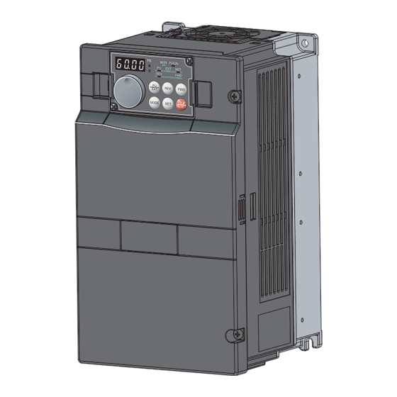
Product checking and parts identification 1.1 Product checking and parts identification Unpack the inverter and check the capacity plate on the front cover and the rating plate on the inverter side face to ensure that the product agrees with your order and the inverter is intact. •... -
Page 14: Inverter And Peripheral Devices
Inverter and peripheral devices 1.2 Inverter and peripheral devices USB connector Three-phase AC power supply A personal computer and an inverter can Use within the permissible power supply be connected with a USB (Ver1. 1) cable. specifications of the inverter. (Refer to page 368) (Refer to page 450) Inverter (FR-A700) -
Page 15: Peripheral Devices
Motor Output Applicable Inverter Model (kW(HP)) Power factor improving Power factor improving (AC or DC) reactor (AC or DC) reactor without with without with 0.4 (1/2) FR-A720-00030-NA/N4 S-N10 S-N10 0.75 (1) FR-A720-00050-NA/N4 S-N10 S-N10 1.5 (2) FR-A720-00080-NA/N4 S-N10 S-N10 2.2 (3) - Page 16 Inverter and peripheral devices 400V class Moulded Case Circuit Breaker (MCCB) or Earth Leakage Input Side Magnetic Contactor Circuit Breaker (ELB) Motor Output Applicable Inverter Model (kW(HP)) Power factor improving Power factor improving (AC or DC) reactor (AC or DC) reactor without with without...
-
Page 17: Method Of Removal And Reinstallation Of The
Method of removal and reinstallation of the front cover 1.3 Method of removal and reinstallation of the front cover Removal of the operation panel 1) Loosen the two screws on the operation panel. 2) Push the left and right hooks of the operation panel (These screws cannot be removed.) and pull the operation panel toward you to remove. - Page 18 Method of removal and reinstallation of the front cover FR-A720-01150 or higher, FR-A740-00570 or higher Removal 1) Remove installation screws on 2) Loosen the installation 3) Pull the front cover 2 toward you to remove the front cover 1 to remove the screws of the front cover 2.
-
Page 19: Installation Of The Inverter And Enclosure Design
Installation of the inverter and enclosure design 1.4 Installation of the inverter and enclosure design When an inverter enclosure is to be designed and manufactured, heat generated by contained equipment, etc., the environment of an operating place, and others must be fully considered to determine the enclosure structure, size and equipment layout. - Page 20 Installation of the inverter and enclosure design (3) Dust, dirt, oil mist Dust and dirt will cause such faults as poor contact of contact points, reduced insulation or reduced cooling effect due to moisture absorption of accumulated dust and dirt, and in-enclosure temperature rise due to clogged filter. In the atmosphere where conductive powder floats, dust and dirt will cause such faults as malfunction, deteriorated insulation and short circuit in a short time.
-
Page 21: Cooling System Types For Inverter Enclosure
Installation of the inverter and enclosure design 1.4.2 Cooling system types for inverter enclosure From the enclosure that contains the inverter, the heat of the inverter and other equipment (transformers, lamps, resistors, etc.) and the incoming heat such as direct sunlight must be dissipated to keep the in-enclosure temperature lower than the permissible temperatures of the in-enclosure equipment including the inverter. - Page 22 Installation of the inverter and enclosure design (2) Clearances around the inverter To ensure ease of heat dissipation and maintenance, leave at least the shown clearances around the inverter. At least the following clearances are required under the inverter as a wiring space, and above the inverter as a heat dissipation space. (front) Surrounding air temperature and humidity Clearances...
- Page 23 MEMO...
-
Page 24: Wiring
WIRING This chapter describes the basic "WIRING" for use of this product. Always read the instructions before using the equipment. 2.1 Wiring ..............14 2.2 Main circuit terminal specifications......16 2.3 Control circuit specifications........26 2.4 Connection of motor with encoder (vector control) .34 2.5 Connection of stand-alone option units ....41... -
Page 25: Wiring
Wiring 2.1 Wiring 2.1.1 Terminal connection diagram Sink logic *1. DC reactor (FR-HEL) *7. A CN8 connector (for MT-BU5) is provided with Brake unit Be sure to connect the DC reactor the FR-A720-02880 (FR-A740-01440) or more. Main circuit terminal (Option) supplied with the FR-A720-02880 (FR- A740-01440) or more. -
Page 26: Emc Filter
Wiring 2.1.2 EMC filter This inverter is equipped with a built-in EMC filter (capacitive filter) and common mode choke. Effective for reduction of air-propagated noise on the input side of the inverter. The EMC filter is factory-set to disable (OFF). To enable it, fit the EMC filter ON/OFF connector to the ON position. -
Page 27: Main Circuit Terminal Specifications
Main circuit terminal specifications 2.2 Main circuit terminal specifications 2.2.1 Specification of main circuit terminal Refer Terminal Terminal Name Description Symbol page R/L1, Connect to the commercial power supply. S/L2, AC power input Keep these terminals open when using the high power factor converter (FR-HC —... -
Page 28: Terminal Arrangement Of The Main Circuit Terminal, Power Supply And The Motor Wiring
Main circuit terminal specifications 2.2.2 Terminal arrangement of the main circuit terminal, power supply and the motor wiring. FR-A720-00030, 00050-NA/N4 FR-A720-00080 to 00175-NA/N4 FR-A740-00015 to 00090-NA/N4 Jumper Jumper R/L1 S/L2 T/L3 Jumper R/L1 S/L2 T/L3 Jumper R1/L11 S1/L21 R1/L11 S1/L21 Power supply Motor Charge lamp... - Page 29 Main circuit terminal specifications FR-A720-02150-NA FR-A740-01100-NA R1/L11 S1/L21 R1/L11 S1/L21 Charge lamp Charge lamp Jumper Jumper R/L1 S/L2 T/L3 N/- R/L1 S/L2 T/L3 Jumper Jumper Power Motor supply Power supply Motor * When using the inverter with LD or SLD set, remove a jumper between P/+ and P1 and connect a DC reactor (option FR- HEL-H90K).
- Page 30 Main circuit terminal specifications CAUTION · The power supply cables must be connected to R/L1, S/L2, T/L3. (Phase sequence needs not to be matched.) Never connect the power cable to the U, V, W of the inverter. Doing so will damage the inverter.
-
Page 31: Cables And Wiring Length
Main circuit terminal specifications 2.2.3 Cables and wiring length (1) Applied cable size Select the recommended cable size to ensure that a voltage drop will be 2% max. If the wiring distance is long between the inverter and motor, a main circuit cable voltage drop will cause the motor torque to decrease especially at the output of a low frequency. - Page 32 Main circuit terminal specifications For the FR-A720-02150 or lower, and FR-A740-01100 or lower, the cable size is that of the cable (HIV cable (600V class 2 vinyl-insulated cable) etc.) with continuous maximum permissible temperature of 75°C (167°F). Assumes that the surrounding air temperature is 50°C (122°F) or less and the wiring distance is 20m (65.62feet) or less.
- Page 33 Main circuit terminal specifications (2) Notes on earthing (grounding) Always earth (ground) the motor and inverter. 1)Purpose of earthing (grounding) Generally, an electrical apparatus has an earth (ground) terminal, which must be connected to the ground before use. An electrical circuit is usually insulated by an insulating material and encased. However, it is impossible to manufacture an insulating material that can shut off a leakage current completely, and actually, a slight current flow into the case.
- Page 34 Main circuit terminal specifications (3) Total wiring length The overall wiring length for connection of a single motor or multiple motors should be within the value in the table below. (The wiring length should be 100m (328.08feet) maximum for vector control.) Pr.
-
Page 35: When Connecting The Control Circuit And The Main Circuit Separately To The Power Supply
Main circuit terminal specifications 2.2.4 When connecting the control circuit and the main circuit separately to the power supply <Connection diagram> When a fault occurs, opening of the electromagnetic contactor (MC) on the inverter power supply side results in power loss in the control circuit, disabling the fault output signal retention. - Page 36 Main circuit terminal specifications FR-A720-00460 or higher, FR-A740-00230 or higher 1) Remove the upper screws. 2) Remove the lower screws. L21 Power supply 3) Pull the jumper toward you to terminal block remove. for the control circuit Power supply terminal block 4) Connect the separate power supply for the control circuit R/L1S/L2 T/L3...
-
Page 37: Control Circuit Specifications
Control circuit specifications 2.3 Control circuit specifications 2.3.1 Control circuit terminals indicates that terminal functions can be selected using Pr. 178 to Pr. 196 (I/O terminal function selection) (Refer to page 235.) (1) Input signals Terminal Terminal Rated Refer to Description Symbol Name... - Page 38 Control circuit specifications Terminal Terminal Rated Refer to Description Symbol Name Specifications page External Connect this terminal to the power supply common terminal of a transistor transistor output (open collector output) device, such as a common programmable controller, in the sink logic to avoid malfunction by Power supply (sink) undesirable currents.
- Page 39 Control circuit specifications Terminal Terminal Rated Refer to Description Symbol Name Specifications page Switched low when the inverter output frequency is equal to or Inverter higher than the starting frequency (initial value 0.5Hz). Switched running high during stop or DC injection brake operation. Switched low when the output Permissible load frequency reaches within the range of...
-
Page 40: Changing The Control Logic
Control circuit specifications 2.3.2 Changing the control logic The input signals are set to sink logic (SINK) when shipped from the factory. To change the control logic, the jumper connector on the back of the control circuit terminal block must be moved to the other position. - Page 41 Control circuit specifications 4) Sink logic and source logic In sink logic, a signal switches ON when a current flows from the corresponding signal input terminal. Terminal SD is common to the contact input signals. Terminal SE is common to the open collector output signals. ...
-
Page 42: Wiring Of Control Circuit
Control circuit specifications 2.3.3 Wiring of control circuit (1) Control circuit terminal layout Control circuit terminal * C2 10E 10 Terminal screw size: M3.5 Tightening torque: 1.2N·m * Refer to instruction manuals of STOP options for the available control terminals other than the standard control circuit terminal. -
Page 43: Wiring Instructions
Control circuit specifications 2.3.4 Wiring instructions It is recommended to use the cables of 0.75mm gauge for connection to the control circuit terminals. If the cable gauge used is 1.25mm or more, the front cover may be lifted when there are many cables running or the cables are run improperly, resulting in an operation panel contact fault. -
Page 44: Mounting The Operation Panel (Fr-Du07) On The Enclosure Surface
Control circuit specifications 2.3.5 Mounting the operation panel (FR-DU07) on the enclosure surface Having an operation panel or a parameter unit on the enclosure surface is convenient. With a connection cable, you can mount the operation panel (FR-DU07) to the enclosure surface, and connect it to the inverter. Use the option FR-CB2, or the following connector and cable available on the market. -
Page 45: Connection Of Motor With Encoder (Vector Control)
Connection of motor with encoder (vector control) 2.4 Connection of motor with encoder (vector control) Orientation control and encoder feedback control, and speed control, torque control and position control by full-scale vector control operation can be performed using a motor with encoder and a plug-in option FR-A7AP. (1) Structure of the FR-A7AP Mounting Terminal... - Page 46 Connection of motor with encoder (vector control) (3) Switches of the FR-A7AP • Encoder specification selection switch (SW1) Differential line Select either differential line driver or complementary driver (initial status) It is initially set to the differential line driver. Switch its position according to output circuit.
- Page 47 Connection of motor with encoder (vector control) (4) Encoder Cable SF-JR Motor with Encoder SF-V5RU, SF-THY Inverter side Encoder side MS3057-12A F-DPEVSB 12P 0.2mm MS3057-12A connector Approx. 140mm (5.51inches) F-DPEVSB 12P 0.2mm Earth cable Earth cable 60mm 60mm (2.36inches) (2.36inches) MS3106B20-29S MS3106B20-29S Type...
- Page 48 Connection of motor with encoder (vector control) Motor SF-V5RU, SF-THY SF-JR/HR/JRCA/HRCA (with Encoder) Encoder cable FR-V7CBL FR-JCBL Keep this open. Keep this open. FR-A7AP terminal Keep this open. (5) Wiring • Speed control Vector control dedicated motor Standard motor with encoder (SF-JR), 5V differential line driver (SF-V5RU, SF-THY), 12V complementary MCCB...
- Page 49 Connection of motor with encoder (vector control) • Position control Vector control dedicated motor (SF-V5RU, SF-THY), 12V complementary MCCB SF-V5RU, SF-THY Three-phase AC power supply MCCB Positioning unit Three-phase R/L1 MELSEQ-Q QD75P1 Inverter AC power S/L2 supply T/L3 Earth (ground) Thermal External thermal protector...
- Page 50 Connection of motor with encoder (vector control) (6) Instructions for encoder cable wiring Example of parallel connection • Use twisted pair shield cables (0.2mm or larger) to connect the FR-A7AP and with two cables position detector. Cables to terminals PG and SD should be connected in (with complementary encoder output) parallel or be larger in size according to the cable length.
- Page 51 Connection of motor with encoder (vector control) Parameters referred to Vector control (speed control) Refer to page 97. Vector control (torque control) Refer to page 123. Vector control (position control) Refer to page 131. Orientation control Refer to page 224. Encoder feedback control Refer to page 389.
-
Page 52: Connection Of Stand-Alone Option Units
Connection of stand-alone option units 2.5 Connection of stand-alone option units The inverter accepts a variety of stand-alone option units as required. Incorrect connection will cause inverter damage or accident. Connect and operate the option unit carefully in accordance with the corresponding option unit manual. 2.5.1 Connection of the dedicated external brake resistor (FR-ABR) The built-in brake resistor is connected across terminals P/+ and PR. - Page 53 Connection of stand-alone option units FR-A720-00460, FR-A740-00230 and 00310 FR-A720-00610 to 00900, FR-A740-00380 and 00440 Connect the brake resistor Connect the brake resistor across terminals P/+ and PR. across terminals P/+ and PR. Jumper * Terminal PR Terminal P/+ Terminal PR Terminal P/+ Jumper Brake resistor...
-
Page 54: Connection Of The Brake Unit (Fr-Bu2)
Connection of stand-alone option units 2.5.2 Connection of the brake unit (FR-BU2) Connect the brake unit (FR-BU2) as shown below to improve the braking capability at deceleration. (1) Connection example with the GRZG type discharging resistor OCR contact GRZG type discharging resistor MCCB External thermal... - Page 55 Connection of stand-alone option units (2) FR-BR-(H) connection example with resistor unit FR-BR MCCB Motor R/L1 Three phase AC S/L2 power supply T/L3 FR-BU2 Inverter 5m or less (16.4 feet) Connect the inverter terminals (P/+, N/-) and brake unit (FR-BU2) terminals so that their terminal names match with each other. (Incorrect connection will damage the inverter and brake unit.) When the power supply is 400V class, install a step-down transformer.
-
Page 56: Connection Of The Brake Unit (Fr-Bu/Mt-Bu5)
Connection of stand-alone option units 2.5.3 Connection of the brake unit (FR-BU/MT-BU5) When connecting the brake unit (FR-BU(H)/MT-BU5) to improve the brake capability at deceleration, make connection as shown below. (1) Connection with the FR-BU (FR-A720-02150 (FR-A740-01100) or lower) FR-BR MCCB Motor R/L1... - Page 57 Connection of stand-alone option units (2) Connection with the MT-BU5 (FR-A720-02800 (FR-A740-01440) or more) After making sure that the MT-BU5 is properly connected, set the following parameters. Pr. 30 Regenerative function selection = "1" Pr. 70 Special regenerative brake duty = "10%" (Refer to page 211) MCCB Motor R/L1...
-
Page 58: Connection Of The Brake Unit (Bu Type)
Connection of stand-alone option units 2.5.4 Connection of the brake unit (BU type) Connect the brake unit (BU type) correctly as shown below. Incorrect connection will damage the inverter. Remove the jumper across terminals HB-PC and terminals TB-HC of the brake unit and fit it to across terminals PC-TB. Inverter MCCB Motor... - Page 59 Connection of stand-alone option units (2) Connection with the MT-HC (FR-A720-02880 (FR-A740-01440) or more) After making sure the wiring is correct, set the following parameters. Pr. 19 Base frequency voltage (under V/F control) or Pr. 83 Rated motor voltage (under a control method other than V/F control) = "rated motor voltage"...
-
Page 60: Connection Of The Power Regeneration Common Converter (Fr-Cv)
Connection of stand-alone option units 2.5.6 Connection of the power regeneration common converter (FR-CV) When connecting the power regeneration common converter (FR-CV), make connection so that the inverter terminals (P/+, N/-) and the terminal symbols of the power regeneration common converter (FR-CV) are the same (FR-A720- 02150 (FR-A740-01100) or less). -
Page 61: Connection Of Power Regeneration Converter (Mt-Rc)
Connection of stand-alone option units 2.5.7 Connection of power regeneration converter (MT-RC) When connecting a power regeneration converter (MT-RC), perform wiring securely as shown below. Incorrect connection will damage the regeneration converter and inverter (FR-A720-02880 (FR-A740-01440) or more). After connecting securely, set "1" in Pr. 30 Regenerative function selection and "0" in Pr. 70 Special regenerative brake duty. Inverter MCCB Three-phase... -
Page 62: Precautions For Use Of The Inverter
PRECAUTIONS FOR USE OF THE INVERTER This chapter explains the "PRECAUTIONS FOR USE OF THE INVERTER" for use of this product. Always read the instructions before using the equipment. 3.1 EMC and leakage currents........52 3.2 Installation of a reactor ..........57 3.3 Power-off and magnetic contactor (MC)....58 3.4 Inverter-driven 400V class motor ......59 3.5 Precautions for use of the inverter ......60... -
Page 63: Emc And Leakage Currents
EMC and leakage currents 3.1 EMC and leakage currents 3.1.1 Leakage currents and countermeasures Capacitances exist between the inverter I/O cables, other cables and earth and in the motor, through which a leakage current flows. Since its value depends on the static capacitances, carrier frequency, etc., low acoustic noise operation at the increased carrier frequency of the inverter will increase the leakage current. - Page 64 EMC and leakage currents (3) Selection of rated sensitivity current of earth (ground) leakage breaker When using the earth (ground) leakage circuit breaker with the inverter circuit, select its rated sensitivity current as follows, independently of the PWM carrier frequency: ...
-
Page 65: Emc Measures
EMC and leakage currents 3.1.2 EMC measures Some electromagnetic noises enter the inverter to malfunction it and others are radiated by the inverter to malfunction peripheral devices. Though the inverter is designed to have high immunity performance, it handles low-level signals, so it requires the following basic techniques. - Page 66 EMC and leakage currents Noise Propagation Measures Path When devices that handle low-level signals and are liable to malfunction due to electromagnetic noises, e.g. instruments, receivers and sensors, are contained in the enclosure that contains the inverter or when their signal cables are run near the inverter, the devices may be malfunctioned by air-propagated electromagnetic noises.
-
Page 67: Power Supply Harmonics
EMC and leakage currents 3.1.3 Power supply harmonics The inverter may generate power supply harmonics from its converter circuit to affect the power generator, power capacitor etc. Power supply harmonics are different from noise and leakage currents in source, frequency band and transmission path. -
Page 68: Installation Of A Reactor
Installation of a reactor 3.2 Installation of a reactor When the inverter is connected near a large-capacity power transformer (1000kVA or more) or when a power capacitor is to be switched over, an excessive peak current may flow in the power input circuit, damaging the converter circuit. To prevent this, always install the optional AC reactor (FR-HAL) AC reactor Inverter... -
Page 69: Power-Off And Magnetic Contactor (Mc)
Power-off and magnetic contactor (MC) 3.3 Power-off and magnetic contactor (MC) (1) Inverter input side magnetic contactor (MC) On the inverter input side, it is recommended to provide an MC for the following purposes. Refer to page 4 for selection.) 1) To release the inverter from the power supply when a fault occurs or when the drive is not functioning (e.g. -
Page 70: Inverter-Driven 400V Class Motor
Inverter-driven 400V class motor 3.4 Inverter-driven 400V class motor In the PWM type inverter, a surge voltage attributable to wiring constants is generated at the motor terminals. Especially for a 400V class motor, the surge voltage may deteriorate the insulation. When the 400V class motor is driven by the inverter, consider the following measures: Measures ... -
Page 71: Precautions For Use Of The Inverter
Precautions for use of the inverter 3.5 Precautions for use of the inverter The FR-A700 series is a highly reliable product, but incorrect peripheral circuit making or operation/handling method may shorten the product life or damage the product. Before starting operation, always recheck the following items. (1) Use crimping terminals with insulation sleeve to wire the power supply and motor. - Page 72 Precautions for use of the inverter (13) Provide electrical and mechanical interlocks for MC1 and MC2 which are used for bypass operation. Interlock When the wiring is incorrect or if there is an electronic bypass Power R/L1 circuit as shown on the right, the inverter will be damaged by supply S/L2 leakage current from the power supply is connected to the...
-
Page 73: Failsafe Of The System Which Uses The Inverter
Failsafe of the system which uses the inverter 3.6 Failsafe of the system which uses the inverter When a fault occurs, the inverter trips to output a fault signal. However, a fault output signal may not be output at an inverter fault occurrence when the detection circuit or output circuit fails, etc. - Page 74 Failsafe of the system which uses the inverter 4) Checking the motor operating status by the start signal input to the inverter and inverter output current detection signal. The output current detection signal (Y12 signal) is output when the inverter operates and currents flows in the motor. Check if Y12 signal is output when inputting the start signal to the inverter (forward signal is STF signal and reverse signal is STR signal).
- Page 75 MEMO...
-
Page 76: Parameters
4 PARAMETERS This chapter explains the "PARAMETERS" for use of this product. Always read this instructions before use. The following marks are used to indicate the controls as below..V/F control ...Advanced magnetic flux vector control Magnetic flux Magnetic flux Magnetic flux ...Real sensorless vector control Sensorless... -
Page 77: Operation Panel (Fr-Du07)
Operation panel (FR-DU07) 4.1 Operation panel (FR-DU07) 4.1.1 Parts of the operation panel (FR-DU07) Operation mode indicator PU: Lit to indicate PU operation mode. EXT: Lit to indicate External operation mode. NET: Lit to indicate Network operation mode. Rotation direction indicator FWD: Lit when forward rotation REV: Lit when reverse rotation Forward/reverse operation... -
Page 78: Basic Operation (Factory Setting)
Operation panel (FR-DU07) 4.1.2 Basic operation (factory setting) Operation mode switchover At power-ON (External operation mode) PU Jog operation mode (Refer to page 68) (Example) Value change and frequency flicker. PU operation mode Frequency setting has been (output frequency monitor) written and completed!! Output current monitor Output voltage monitor... -
Page 79: Changing The Parameter Setting Value
Operation panel (FR-DU07) 4.1.3 Changing the parameter setting value Changing example Change the Pr. 1 Maximum frequency . Operation Screen at power-ON The monitor display appears. Operation mode change Press to choose the PU operation mode. [PU] indicator is lit. Parameter setting mode Press to choose the parameter setting mode. -
Page 80: Parameter List
Parameter List 4.2 Parameter List 4.2.1 Parameter list For simple variable-speed operation of the inverter, the initial setting of the parameters may be used as they are. Set the necessary parameters to meet the load and operational specifications. Parameter setting, change and check can be made from the operation panel (FR-DU07). - Page 81 Parameter List Minimum Refer Func- Customer Parameter Name Setting Range Setting Initial Value tion Setting Increments Page Up-to-frequency sensitivity 0 to 100% 0.1% Output frequency detection 0 to 400Hz 0.01Hz Output frequency detection for reverse 0 to 400Hz, 9999 0.01Hz 9999 rotation Second acceleration/deceleration time...
- Page 82 Parameter List Minimum Refer Func- Customer Parameter Name Setting Range Setting Initial Value tion Setting Increments Page 0.4 to 55kW, 9999/ 147, 0.01/0.1kW 9999 Motor capacity 0 to 3600kW, 9999 147, 2, 4, 6, 8, 10, 12, 14, 16, 9999 Number of motor poles 18, 20, 9999 0 to 500A, 9999/...
- Page 83 Parameter List Minimum Refer Func- Customer Parameter Name Setting Range Setting Initial Value tion Setting Increments Page PID control automatic switchover 0.01Hz 9999 0 to 400Hz, 9999 frequency 10, 11, 20, 21, 50, 51, 60, PID action selection 61, 70, 71, 80, 81, 90, 91, 100, 101 PID proportional band 0.1 to 1000%, 9999...
- Page 84 Parameter List Minimum Refer Func- Customer Parameter Name Setting Range Setting Initial Value tion Setting Increments Page Output current detection signal 0 to 10s, 9999 0.1s 0.1s retention time Output current detection operation 0, 1 selection Parameter for manufacturer setting. Do not set. ...
- Page 85 Parameter List Minimum Refer Func- Customer Parameter Name Setting Range Setting Initial Value tion Setting Increments Page RUN terminal function selection 0 to 8, 10 to 20, 25 to 28, 30 to 36, 39, 41 to 47, 55, SU terminal function selection 64, 70, 84, 85, 90 to 99, 100 to 108, 110 to 116, IPF terminal function selection...
- Page 86 Parameter List Minimum Refer Func- Customer Parameter Name Setting Range Setting Initial Value tion Setting Increments Page Power failure stop selection 0, 1, 2, 11, 12 Subtracted frequency at deceleration 0.01Hz 0 to 20Hz start Subtraction starting frequency 0 to 120Hz, 9999 0.01Hz 0.1/0.01s Power-failure deceleration time 1...
- Page 87 Parameter List Minimum Refer Func- Customer Parameter Name Setting Range Setting Initial Value tion Setting Increments Page RS-485 communication station number 0 to 31(0 to 247) 3, 6, 12, 24, RS-485 communication speed 48, 96, 192, 384 RS-485 communication stop bit length 0, 1, 10, 11 RS-485 communication parity check 0, 1, 2...
- Page 88 Parameter List Minimum Refer Func- Customer Parameter Name Setting Range Setting Initial Value tion Setting Increments Page Orientation selection Orientation speed gain (P term) 0 to 1000 0.001s 0.333s Orientation speed integral time 0 to 20s Orientation speed gain (D term) 0 to 100 Orientation deceleration ratio 0 to 1000...
- Page 89 Parameter List Minimum Refer Func- Customer Parameter Name Setting Range Setting Initial Value tion Setting Increments Page Digital position control sudden stop 0 to 360.0s 0.1s deceleration time First position feed amount lower 4 digits 0 to 9999 First position feed amount upper 4 digits 0 to 9999 Second position feed amount lower 4 digits 0 to 9999 Second position feed amount upper 4 digits 0 to 9999...
- Page 90 Parameter List Minimum Refer Func- Customer Parameter Name Setting Range Setting Initial Value tion Setting Increments Page S-pattern time at a start of acceleration 0.1 to 2.5s 0.1s 0.1s S-pattern time at a completion of 0.1s 0.1s 0.1 to 2.5s acceleration 0.1s 0.1s...
- Page 91 Parameter List Minimum Refer Func- Customer Parameter Name Setting Range Setting Initial Value tion Setting Increments Page Speed limit selection 0, 1, 2 0.01Hz Forward rotation speed limit 0 to 120Hz 0.01Hz 9999 Reverse rotation speed limit 0 to 120Hz, 9999 Torque limit input method selection 0, 1 Set resolution switchover...
- Page 92 Parameter List Minimum Refer Func- Customer Parameter Name Setting Range Setting Initial Value tion Setting Increments Page Analog input offset adjustment 0 to 200% 0.1% 100% Brake operation selection 0, 1, 2 Speed deviation time 0 to 100s 0.1s 100% Excitation ratio 0 to 100% Terminal 4 function assignment...
- Page 93 Parameter List Minimum Refer Func- Customer Parameter Name Setting Range Setting Initial Value tion Setting Increments Page Cumulative power monitor digit shifted 0 to 4, 9999 9999 times 0.1% 100% Load factor 30 to 150% Inverter Energy saving monitor reference 0.01/ 0.1 to 55/0 to 3600kW rated...
- Page 94 Parameter List Minimum Refer Func- Customer Parameter Name Setting Range Setting Initial Value tion Setting Increments Page Pr. CL Parameter clear 0, 1 ALLC All parameter clear 0, 1 Er.CL Faults history clear 0, 1 PCPY Parameter copy 0, 1, 2, 3 Differ according to capacities.
- Page 95 Parameters according to purposes Control mode 4.3.1 What is vector control?..........................88 4.3.2 Change the control method (Pr. 80, Pr. 81, Pr. 451, Pr. 800) ..............91 Speed control by Real sensorless vector control, vector control 4.4.1 Setting procedure of Real sensorless vector control (speed control) ............97 4.4.2 Setting procedure of vector control (speed control) ...................
- Page 96 4.12.3 Acceleration/deceleration pattern (Pr. 29, Pr. 140 to Pr. 143, Pr. 380 to Pr. 383, Pr. 516 to Pr. 519)............................. 178 4.12.4 Shortest acceleration/deceleration and optimum acceleration/deceleration (automatic acceleration/deceleration) (Pr. 61 to Pr. 63, Pr. 292, Pr. 293) ..........182 4.13 Selection and protection of a motor 4.13.1 Motor protection from overheat (Electronic thermal relay function) (Pr.
- Page 97 4.21.4 Response level of analog input and noise elimination (Pr. 74, Pr. 822, Pr. 826, Pr. 832, Pr. 836, Pr. 849) .................. 297 4.21.5 Bias and gain of frequency setting voltage (current) (Pr. 125, Pr. 126, Pr. 241, C2(Pr. 902) to C7(Pr. 905), C12(Pr. 917) to C15(Pr. 918))......299 4.21.6 Bias and gain of torque (magnetic flux) setting voltage (current) (Pr.
-
Page 98: Control Mode
Control mode Control mode V/F control (initial setting), Advanced magnetic flux vector control, Real sensorless vector control and vector control are available with this inverter. V/F Control It controls frequency and voltage so that the ratio of frequency (F) to voltage (V) is constant when changing frequency. Advanced magnetic flux vector control ... -
Page 99: What Is Vector Control
Control mode 4.3.1 What is vector control? Vector control is one of the control techniques for driving an induction motor. To help explain vector control, the fundamental equivalent circuit of an induction motor is shown below: r1 : Primary resistance r2 : Secondary resistance : Primary leakage inductance : Secondary leakage inductance... - Page 100 Control mode Block diagram of Real sensorless vector control modulation magnetic pre-excitation φ 2 flux current output control control voltage conversion torque ω speed ω 0 current control control ω FB ω 0 ω FB ω s current conversion slip calculation φ...
- Page 101 Control mode (1) Speed control Speed control operation is performed to zero the difference between the speed command (*) and actual rotation detection value (FB). At this time, the motor load is found and its result is transferred to the torque current controller as a torque current command (iq*).
-
Page 102: Change The Control Method (Pr. 80, Pr. 81, Pr. 451, Pr. 800)
Control mode 4.3.2 Change the control method (Pr. 80, Pr. 81, Pr. 451, Pr. 800) Set when selecting the Advanced magnetic flux vector control, Real sensorless vector control or vector control. Select a control mode from speed control mode, torque control mode and position control mode under Real sensorless vector control or vector control. - Page 103 Control mode Vector control test operation (Pr. 800 = "9") Speed control test operation can be performed even when the motor is not connected. The speed calculation value changes to track the speed command and the transition can be checked with the operation panel and analog signal output at FM and AM.
- Page 104 Control mode Switching the control method from the external terminal (MC signal) When "12 (2)" is set in Pr. 800 (Pr. 451 ), speed control is selected when the control mode switching signal (MC) is OFF, and torque control is selected when the signal is OFF under Real sensorless vector control and vector control.
- Page 105 Control mode Terminal 4 function according to control Real Sensorless Vector Control (Pr. 800 = 12), Vector Control (Pr. 800 = 2) Pr. 858 Setting Speed control (MC signal-OFF) Torque control (MC signal-ON) 0 (initial value) Speed command (AU signal-ON) Speed limit (AU signal-ON) Magnetic flux command * Magnetic flux command *...
-
Page 106: Speed Control By Real Sensorless Vector Control, Vector Control
Speed control by Real sensorless vector control, vector control 4.4 Speed control by Real sensorless vector control, vector control Purpose Parameter that should be Set Refer to Page Pr. 22, Pr. 803, Pr. 810, To perform torque limit during speed control Torque limit Pr. - Page 107 Speed control by Real sensorless vector control, vector control Speed feed forward control Speed feed forward Speed feed torque limit forward [Pr. 879] filter [Pr. 878] Load inertia ratio Speed feed forward gain [Pr. 880] [Pr. 881] Model adaptive speed control J [Pr.
-
Page 108: Setting Procedure Of Real Sensorless Vector Control (Speed Control)
Speed control by Real sensorless vector control, vector control 4.4.1 Setting procedure of Real sensorless vector control (speed control) Sensorless Sensorless Sensorless Perform secure wiring. (Refer to page 14.) Set the motor. (Pr. 71) (Refer to page 189.) Set "3" (standard motor) or "13" (constant-torque motor) in Pr. 71 Applied motor. -
Page 109: Setting Procedure Of Vector Control (Speed Control)
Speed control by Real sensorless vector control, vector control 4.4.2 Setting procedure of vector control (speed control) Vector Vector Vector Perform secure wiring. (Refer to page 37.) Mount the FR-A7AP/FR-A7AL (option). Set the motor and encoder. (Pr. 71, Pr. 359, Pr. 369) Set Pr. -
Page 110: Torque Limit Level Setting For Speed Control (Pr. 22, Pr. 157, Pr. 803, Pr. 810 To Pr. 817, Pr. 858, Pr. 868, Pr. 874)
Speed control by Real sensorless vector control, vector control 4.4.3 Torque limit level setting for speed control (Pr. 22, Pr. 157, Pr. 803, Pr. 810 to Pr. 817, Pr. 858, Pr. 868, Pr. 874) Sensorless Sensorless Sensorless Vector Vector Vector This function limits the output torque to the predetermined value during speed control under Real sensorless vector control or vector control. - Page 111 Speed control by Real sensorless vector control, vector control (1) Torque limit block diagram <Vector control> Torque limit Speed control Iq current control Speed command + Encoder (2) Selection of torque limit input method (Pr. 810) Set Pr. 810 Torque limit input method selection to select the method to limit output torque during speed control. Torque limit by parameter setting is initially set.
- Page 112 Speed control by Real sensorless vector control, vector control Terminal 1, 4 function according to control ( : without function) Real Sensorless Vector Control (Speed Control) Pr. 858 Setting Pr. 868 Setting Terminal 4 function Terminal 1 function Speed setting auxiliary (initial value) Magnetic flux command...
- Page 113 Speed control by Real sensorless vector control, vector control (6) Set a torque limit value during acceleration and deceleration individually (Pr. 816, Pr. 817 ) You can set torque limit during acceleration and deceleration individually. The following chart shows torque limit according to the settings of Pr. 816 Torque limit level during acceleration and Pr. 817 Torque limit level during deceleration.
- Page 114 Speed control by Real sensorless vector control, vector control (9) Trip when torque limit is activated (Pr. 874 ) This function can cause a trip if the torque limit is activated Torque to stall the motor. The motor stalls if the torque limit is activated under a high load applied during speed control or position control.
-
Page 115: To Perform High Accuracy/Fast Response Operation (Gain Adjustment Of Real Sensorless Vector Control And Vector Control) (Pr. 818 To Pr. 821, Pr. 830, Pr. 831, Pr. 880)
Speed control by Real sensorless vector control, vector control 4.4.4 To perform high accuracy/fast response operation (gain adjustment of Real sensorless vector control and vector control) (Pr. 818 to Pr. 821, Pr. 830, Pr. 831, Pr. 880) Sensorless Sensorless Sensorless Vector Vector Vector... - Page 116 Speed control by Real sensorless vector control, vector control (2) Easy gain tuning execution procedure (Pr. 819 = "1" load inertia ratio automatic estimation) Easy gain tuning (load inertia ratio automatic estimation) is valid only in the speed control or Pr.
- Page 117 Speed control by Real sensorless vector control, vector control (4) Parameters automatically set by easy gain tuning The following table indicates the relationship between easy gain tuning function and gain adjustment parameter. Easy Gain Tuning Selection (Pr. 819 ) Setting a) Inertia estimation result (RAM) by easy gain tuning is displayed.
- Page 118 Speed control by Real sensorless vector control, vector control (5) Manual input speed control gain adjustment · Make adjustment when any of such phenomena as unusual machine vibration/noise, low response level and overshoot has occurred. Proportional gain · Pr. 820 Speed control P gain 1 = "60%" (initial value) is equivalent to 120rad/s (speed response of the motor alone).
- Page 119 Speed control by Real sensorless vector control, vector control (6) When using a multi-pole motor (8 poles or more) Specially when using a multi-pole motor with more than 8 poles under Real sensorless vector control or vector control, adjust Pr. 820 Speed control P gain 1 and Pr. 824 Torque control P gain 1 according to the motor referring to the following methods.
- Page 120 Speed control by Real sensorless vector control, vector control (8) Troubleshooting (speed) Phenomenon Cause Countermeasures (1) The motor wiring is wrong (1) Wiring check Select V/F control (set "9999" in Pr. 80 or Pr. 81 ) and check the rotation direction of the motor. For the SF-V5RU (1500r/min series), set "170V(340V)"...
- Page 121 Speed control by Real sensorless vector control, vector control Phenomenon Cause Countermeasures (1) The speed command varies. (1) -1 Check that a correct speed command comes from the command device. (Take measures against noises.) (1) -2 Decrease Pr. 72 PWM frequency selection. (1) -3 Increase Pr.
-
Page 122: Speed Feed Forward Control, Model Adaptive Speed Control (Pr. 828, Pr. 877 To Pr. 881)
Speed control by Real sensorless vector control, vector control 4.4.5 Speed feed forward control, model adaptive speed control (Pr. 828, Pr. 877 to Pr. 881) Sensorless Sensorless Sensorless Vector Vector Vector By making parameter setting, select the speed feed forward control or model adaptive speed control. The speed feed forward control enhances the trackability of the motor in response to a speed command change. - Page 123 Speed control by Real sensorless vector control, vector control (2) Model adaptive speed control (Pr. 877 = "2") The motor's model speed is calculated to feed back the model side speed controller. This model speed is also used as the actual speed controller command. ...
-
Page 124: Torque Biases (Pr. 840 To Pr. 848)
Speed control by Real sensorless vector control, vector control 4.4.6 Torque biases (Pr. 840 to Pr. 848) Vector Vector Vector This function accelerates the rise of the torque at a start. Adjust the torque at a motor start using the contact signals or analog signals . - Page 125 Speed control by Real sensorless vector control, vector control (2) Setting torque bias amount with the contact input (Pr. 840 = "0") Select the torque bias amount in the table below according to the combination of contact signals. Set "42" in Pr. 178 to Pr. 189 (input terminal function selection) for the terminal used for X42 signal input and set "43" for the terminal used for X43 signal input to assign functions.
- Page 126 Speed control by Real sensorless vector control, vector control (4) Setting torque bias amount with terminal 1 (Pr. 840 = "3") C16 Terminal 1 bias command (torque/magnetic flux), C17 Terminal 1 bias (torque/magnetic flux), C18 Terminal 1 gain command (torque/magnetic flux), C19 Terminal 1 gain (torque/magnetic flux), and Pr. 846 Torque bias balance compensation can be set automatically according to the load.
-
Page 127: Prevent The Motor From Overrunning (Pr. 285, Pr. 853, Pr. 873)
Speed control by Real sensorless vector control, vector control 4.4.7 Prevent the motor from overrunning (Pr. 285, Pr. 853, Pr. 873) Vector Vector Vector This function prevents the motor from overrunning when the load torque is too large and incorrect number of encoder is set. -
Page 128: Notch Filter (Pr. 862, Pr. 863)
Speed control by Real sensorless vector control, vector control 4.4.8 Notch filter (Pr. 862, Pr. 863) Sensorless Sensorless Sensorless Vector Vector Vector You can reduce the response level of speed control in the resonance frequency band of the mechanical system to avoid mechanical resonance. -
Page 129: Torque Control By Real Sensorless Vector Control, Vector Control
Torque control by Real sensorless vector control, vector control 4.5 Torque control by Real sensorless vector control, vector control Purpose Parameter that must be Set Refer to Page Selection of torque command source and setting of torque Torque command Pr. 803 to Pr. 806 command value Prevent the motor overspeed Speed limit... - Page 130 Torque control by Real sensorless vector control, vector control Speed limit Analog input offset adjustment Terminal 2 bias [C2, C3 (Pr. 902)] [Pr. 849] Terminal 2 gain [Pr. 125, C4 (Pr. 903)] Terminal 2 Analog input Terminal 4 bias [C5, C6 (Pr. 904)] selection Terminal 4 gain [Pr.
- Page 131 Torque control by Real sensorless vector control, vector control (2) Operation transition Speed limit value is increased up to preset value according to the Pr.7 Speed limit value is decreased Speed limit value Acceleration time setting. down to zero according to the Pr.8 Deceleration time setting.
- Page 132 Torque control by Real sensorless vector control, vector control (3) Operation example (when Pr. 804 = "0") Torque control is enabled if the actual speed is less than the speed limit value. When the actual speed reaches or exceeds the speed limit value, speed limit operation starts, torque control is stopped, and speed control (proportional control) starts.
-
Page 133: Setting Procedure Of Real Sensorless Vector Control (Torque Control)
Torque control by Real sensorless vector control, vector control 4.5.2 Setting procedure of Real sensorless vector control (torque control) Sensorless Sensorless Sensorless Perform secure wiring. (Refer to page 14.) Set the motor. (Pr. 71) (Refer to page 189.) Set "3" (standard motor) or "13" (constant torque motor) in Pr. 71 Applied motor. -
Page 134: Setting Procedure Of Vector Control (Torque Control)
Torque control by Real sensorless vector control, vector control 4.5.3 Setting procedure of vector control (torque control) Vector Vector Vector Perform secure wiring. (Refer to page 37.) Mount the FR-A7AP/FR-A7AL (option). Set the motor and encoder. (Pr. 71, Pr. 359, Pr. 369) Set Pr. -
Page 135: Torque Command (Pr. 803 To Pr. 806)
Torque control by Real sensorless vector control, vector control 4.5.4 Torque command (Pr. 803 to Pr. 806) Sensorless Sensorless Sensorless Vector Vector Vector Torque command source for torque control can be selected. Parameter Initial Setting Name Description Number Value Range Constant motor output Constant power range Select the torque command in the... - Page 136 Torque control by Real sensorless vector control, vector control (3) Torque command using parameters (Pr. 804 = "1") Torque command value can be set by setting Pr. 805 Torque command value Torque command value (RAM) or Pr. 806 Torque command value (RAM,EEPROM) .
-
Page 137: Speed Limit (Pr. 807 To Pr. 809)
Torque control by Real sensorless vector control, vector control (7) Change the torque characteristics in the constant power (Pr. 803) Due to the motor characteristics, torque is reduced at or Torque Constant power range above the base frequency. Set "1" in Pr. 803 Constant Constant torque range Pr. - Page 138 Torque control by Real sensorless vector control, vector control (2) Use the speed command for speed control (Pr. 807 = "0" initial value) The speed setting Speed value is a speed Set the speed limit in the same method as speed setting Forward rotation limit value.
- Page 139 Torque control by Real sensorless vector control, vector control (4) Forward rotation/reverse rotation speed limit (Pr. 807 = "2") When making a speed limit using analog input from terminal 1, the speed limit of the forward and reverse rotation can be switched according to the polarity of voltage.
-
Page 140: Gain Adjustment Of Torque Control (Pr. 824, Pr. 825, Pr. 834, Pr. 835)
Torque control by Real sensorless vector control, vector control 4.5.6 Gain adjustment of torque control (Pr. 824, Pr. 825, Pr. 834, Pr. 835) Sensorless Sensorless Sensorless Vector Vector Vector Although stable operation is possible with the initial value, make adjustment when any of such phenomena as unusual motor and machine vibration/noise and overcurrent has occurred. - Page 141 Torque control by Real sensorless vector control, vector control (4) Adjustment procedure Make adjustment when any of such phenomena as unusual motor and machine vibration/noise/current and overcurrent has occurred. 1)Check the conditions and simultaneously change the Pr. 824 value. 2)If you cannot make proper adjustment, change the Pr. 825 value and repeat step 1). Adjustment Method Set Pr.
-
Page 142: Position Control By Vector Control
Position control by vector control 4.6 Position control by vector control Purpose Parameter that must be Set Refer to Page Simple position control by Position command by Pr. 419, Pr. 464 to Pr. 494 parameter setting parameter Position control by pulse train input Position command by Pr. - Page 143 Position control by vector control (2) Control block diagram Position command source selection Pr. 4 to 6 Position feed Pr. 465 to Pr. 494 forward Pr. 24 to 27 Pr. 419 travel Position feed command filter Multi-speed, Pr. 232 to 239 forward gain communication Pr.
-
Page 144: Simple Position Feed Function By Contact Input (Pr. 419, Pr. 464 To Pr. 494)
Position control by vector control REMARKS For the servo ON signal (LX), set "23" in Pr. 178 to Pr. 189 (input terminal function selection) to assign the function. For the in-position signal (Y36), set "36" in Pr. 190 to Pr. 196 (output terminal function selection) to assign the function. CAUTION Changing the terminal function using any of Pr. - Page 145 Position control by vector control Selection Method Parameter Setting Position feed (OFF: ON: ) Name Initial Value Number Range frequency Seventh position feed 0 to 9999 amount lower 4 digits 7 speed (Pr. 27) Seventh position feed 0 to 9999 amount upper 4 digits Eighth position feed...
- Page 146 Position control by vector control (1) Setting of position feed amount by parameter Set position feed amount in Pr. 465 to Pr. 494 . The feed amount set in each parameter is selected by multi-speed terminal (RH, RM, RL, REX). Set (encoder resolution ...
-
Page 147: Position Control (Pr. 419, Pr. 428 To Pr. 430) By Inverter Pulse Train Input
Position control by vector control 4.6.3 Position control (Pr. 419, Pr. 428 to Pr. 430) by inverter pulse train input Vector Vector Vector Simple position pulse train command can be input by pulse train input and sign signal (NP) to the JOG terminal. Parameter Setting Name... - Page 148 Position control by vector control (3) Selection of clear signal (Pr. 429, CLR signal) Use this function to zero the droop pulse for home position operation, etc. When "0" is set in Pr. 429 , the deviation counter is cleared at the edge of turning ON of the clear signal (CLR). In addition, the CLR signal turns ON in synchronization with zero pulse signal of the encoder at home position operation, etc., deviation counter is cleared.
-
Page 149: Setting Of The Electronic Gear (Pr. 420, Pr. 421, Pr. 424)
Position control by vector control 4.6.4 Setting of the electronic gear (Pr. 420, Pr. 421, Pr. 424) Vector Vector Vector Set the ratio of the machine side gear and the motor side gear. Parameter Setting Name Initial Value Description Number Range Command pulse scaling 0 to 32767 *... -
Page 150: Setting Of Positioning Adjustment Parameter (Pr. 426, Pr. 427)
Position control by vector control Relationship between position resolution and overall accuracy Since overall accuracy (positioning accuracy of machine) is the sum of electrical error and mechanical error, normally take measures to prevent the electrical system error from affecting the overall error. As a guideline, refer to the following relationship. -
Page 151: Gain Adjustment Of Position Control (Pr. 422, Pr. 423, Pr. 425)
Position control by vector control 4.6.6 Gain adjustment of position control (Pr. 422, Pr. 423, Pr. 425) Vector Vector Vector Easy gain tuning is available as an easy tuning method. Refer to page 104 for easy gain tuning. If it does not produce any effect, make fine adjustment by using the following parameters. Set "0"... - Page 152 Position control by vector control (3) Troubleshooting (Position) Phenomenon Cause Countermeasures (1) The phase sequence of the (1) Check the wiring. (Refer to page 37 ) motor or encoder wiring is wrong. (2) The control mode selection Pr. (2) Check the Pr. 800 setting. (Refer to page 91 ) 800 setting is improper.
-
Page 153: Trouble Shooting For When Position Control Is Not Exercised Normally
Position control by vector control 4.6.7 Trouble shooting for when position control is not exercised normally Vector Vector Vector Position control is not exercised normally Have you checked the speed control items? Check the speed control measures. Position shift occurs. Have you made the electronic gear setting? -
Page 154: Adjustment Of Real Sensorless Vector Control, Vector Control
Adjustment of Real sensorless vector control, vector control 4.7 Adjustment of Real sensorless vector control, vector control Purpose Parameter that should be Set Refer to Page Speed detection filter Stabilize speed and feedback signal Pr. 823, Pr. 827, Pr. 833, Pr. 837 Torque detection filter Change the excitation ratio Excitation ratio... -
Page 155: Excitation Ratio (Pr. 854)
Adjustment of Real sensorless vector control, vector control 4.7.2 Excitation ratio (Pr. 854) Sensorless Sensorless Sensorless Sensorless Sensorless Sensorless Sensorless Sensorless Sensorless Vector Vector Vector Decrease the excitation ratio when you want to improve efficiency under light load. (Motor magnetic noise decreases.) Parameter Name... -
Page 156: Adjustment Of The Output Torque (Current) Of The Motor
Adjustment of the output torque (current) of the motor 4.8 Adjustment of the output torque (current) of the motor Purpose Parameter that must be Set Refer to Page Set starting torque manually Manual torque boost Pr. 0, Pr. 46, Pr. 112 Pr. - Page 157 Adjustment of the output torque (current) of the motor (2) Set multiple torque boost (RT signal, X9 signal, Pr. 46, Pr. 112) Use the second (third) torque boost when changing the torque boost according to application or when using multiple motors by switching between them by one inverter.
-
Page 158: Advanced Magnetic Flux Vector Control (Pr. 71, Pr. 80, Pr. 81, Pr. 89, Pr. 450, Pr. 451, Pr. 453, Pr. 454, Pr. 569, Pr. 800)
Adjustment of the output torque (current) of the motor 4.8.2 Advanced magnetic flux vector control (Pr. 71, Pr. 80, Pr. 81, Pr. 89, Pr. 450, Pr. 451, Pr. 453, Pr. 454, Pr. 569, Pr. 800) Magnetic flux Magnetic flux Magnetic flux Advanced magnetic flux vector control can be selected by setting the capacity, number and type of motor to be used in Pr. - Page 159 Adjustment of the output torque (current) of the motor POINT If the following conditions are not satisfied, select V/F control since malfunction such as insufficient torque and uneven rotation may occur. • The motor capacity should be equal to or one rank lower than the inverter capacity. (note that the capacity should be 0.4kW or more) •...
- Page 160 Adjustment of the output torque (current) of the motor (1) Selection method of Advanced magnetic flux vector control Perform secure wiring. (Refer to page 14) Set the motor. (Pr. 71) Motor Pr. 71 Setting REMARKS SF-JR 0 (initial value) Mitsubishi standard SF-JR 4P 1.5kW or less motor Mitsubishi high...
- Page 161 Adjustment of the output torque (current) of the motor CAUTION · Uneven rotation slightly increases as compared to the V/F control. (It is not suitable for machines such as grinding machine and wrapping machine which requires less uneven rotation at low speed.) ·...
-
Page 162: Slip Compensation (Pr. 245 To Pr. 247)
Adjustment of the output torque (current) of the motor 4.8.3 Slip compensation (Pr. 245 to Pr. 247) The inverter output current may be used to assume motor slip to keep the motor speed constant. Parameter Name Initial Value Setting Range Description Number 0.01 to 50%... -
Page 163: Stall Prevention Operation
Adjustment of the output torque (current) of the motor 4.8.4 Stall prevention operation (Pr. 22, Pr. 23, Pr. 48, Pr. 49, Pr. 66, Pr. 114, Pr. 115, Pr. 148, Pr. 149, Pr. 154, Pr. 156, Pr. 157, Pr. 858, Pr. 868) Magnetic flux Magnetic flux Magnetic flux... - Page 164 Adjustment of the output torque (current) of the motor CAUTION If an overload status lasts long, an inverter trip (e.g. electronic thermal relay function (E.THM)) may occur. When Pr. 156 has been set to activate the fast response current limit (initial setting), the Pr. 22 setting should not be higher than 170%.
- Page 165 Adjustment of the output torque (current) of the motor (4) Set multiple stall prevention operation levels (Pr. 48, Pr. 49, Pr. 114, Pr. 115) Setting "9999" in Pr. 49 Second stall prevention operation frequency and turning the RT signal ON make Pr. 48 Second stall prevention operation current valid.
- Page 166 Adjustment of the output torque (current) of the motor (5) Stall prevention operation level setting by terminal 1 (terminal 4) (analog variable) (Pr. 148, Pr. 149, Pr. 858, Pr. 868) To set the stall prevention operation level using terminal 1 (analog input), set Pr. 868 Terminal 1 Current limit level (%) Set the current limit level at 10V/5V input function assignment to "4".
- Page 167 Adjustment of the output torque (current) of the motor (7) Limit the stall prevention operation and fast response current limit operation according to the operating status (Pr. 156) Refer to the following table and select whether fast response current limit operation will be performed or not and the operation to be performed at OL signal output.
-
Page 168: Multiple Rating (Pr. 570)
Adjustment of the output torque (current) of the motor 4.8.5 Multiple rating (Pr. 570) You can use the inverter by changing the overload current rating specifications according to load applications. Note that the control rating of each function changes. Parameter Setting Name Initial Value... - Page 169 Adjustment of the output torque (current) of the motor Pr. 570 Setting Refer Parameter Name Number Page (initial value) 0 to 120% 0 to 150% 0 to 220% 0 to 280% Setting Range Zero current detection level Initial Value Stall prevention Setting Range 0 to 120% 0 to 150%...
-
Page 170: Limiting The Output Frequency
Limiting the output frequency 4.9 Limiting the output frequency Purpose Parameter that must be Set Refer to Page Set upper limit and lower limit of Maximum/minimum Pr. 1, Pr. 2, Pr. 18 output frequency frequency Perform operation by avoiding Frequency jump Pr. -
Page 171: Avoiding Mechanical Resonance Points (Frequency Jump) (Pr. 31 To Pr. 36)
Limiting the output frequency 4.9.2 Avoiding mechanical resonance points (Frequency jump) (Pr. 31 to Pr. 36) When it is desired to avoid resonance attributable to the natural frequency of a mechanical system, these parameters allow resonant frequencies to be jumped. Parameter Name Initial Value... -
Page 172: V/F Pattern
V/F pattern 4.10 V/F pattern Purpose Parameter that must be Set Refer to Page Base frequency, base Set motor ratings Pr. 3, Pr. 19, Pr. 47, Pr. 113 frequency voltage Select a V/F pattern according to Load pattern selection Pr. 14 applications Automatically set a V/F pattern for Elevator mode (automatic... - Page 173 V/F pattern (3) Base frequency voltage setting (Pr. 19) Use Pr. 19 Base frequency voltage to set the base voltage (e.g. rated motor voltage). If the setting is less than the power supply voltage, the maximum output voltage of the inverter is as set in Pr. 19. ...
-
Page 174: Load Pattern Selection (Pr. 14)
V/F pattern 4.10.2 Load pattern selection (Pr. 14) You can select the optimum output characteristic (V/F characteristic) for the application and load characteristics. Parameter Name Initial Value Setting Range Description Number For constant torque load For variable-torque load For constant torque elevators (at reverse rotation boost of 0%) For constant torque elevators (at forward rotation boost of 0%) - Page 175 V/F pattern (4) Change load pattern selection using Pr. 14 RT(X17) Signal Output Characteristics Setting terminal (setting values are "4, 5") For constant torque load Output characteristic can be switched between for (same as when the setting constant torque load and for elevator using the RT is "0") signal or X17 signal.
-
Page 176: Elevator Mode (Automatic Acceleration/Deceleration) (Pr. 61, Pr. 64, Pr. 292)
V/F pattern 4.10.3 Elevator mode (automatic acceleration/deceleration) (Pr. 61, Pr. 64, Pr. 292) Operation matching a load characteristic of elevator with counterweight can be performed. Setting Range Parameter Initial Name Description Number Value 200V class (400V class) 02150 (01100) 0 to 500A or less Set the reference current for elevator mode. - Page 177 V/F pattern (2) Adjustment of elevator mode (Pr. 61, Pr. 64) By setting the adjustment parameters Pr. 61 and Pr. 64, the application range can be made wider. Setting Range Parameter Name Description Number 200V class (400V class) 02150 (01100) 0 to 500A For example, when the motor and inverter are different in or less...
-
Page 178: Adjustable 5 Points V/F (Pr. 71, Pr. 100 To Pr. 109)
V/F pattern 4.10.4 Adjustable 5 points V/F (Pr. 71, Pr. 100 to Pr. 109) A dedicated V/F pattern can be made by freely setting the V/F characteristic between a startup and the base frequency and base voltage under V/F control (frequency voltage/frequency). The torque pattern that is optimum for the machine's characteristic can be set. -
Page 179: Frequency Setting By External Terminals
Frequency setting by external terminals 4.11 Frequency setting by external terminals Purpose Parameter that must be Set Refer to Page Make frequency setting by Pr. 4 to Pr. 6, Pr. 24 to Pr. 27, Multi-speed operation combination of terminals Pr. 232 to Pr. 239 Perform jog operation Jog operation Pr. - Page 180 Frequency setting by external terminals (2) Multi-speed setting higher than speed 4 (Pr. 24 to Pr. 27, Pr. 232 to Pr. 239) Frequency from speed 4 to speed 15 can be set according to the combination of the RH, RM, RL and REX signals. Set the running frequencies in Pr.
-
Page 181: Jog Operation (Pr. 15, Pr. 16)
Frequency setting by external terminals 4.11.2 Jog operation (Pr. 15, Pr. 16) You can set the frequency and acceleration/deceleration time for Jog operation. Jog operation can be performed from either the outside or PU. Can be used for conveyor positioning, test operation, etc. Parameter Initial Name... - Page 182 Frequency setting by external terminals (2) Jog operation from PU Inverter Set the PU (FR-DU07/FR-PU07/FR-PU04) to the jog operation mode. Operation is performed only Three-phase AC Motor power supply while the start button is pressed. FR-DU07 Operation Indication Confirmation of the RUN indication and operation mode indication The monitor mode should have been selected.
-
Page 183: Input Compensation Of Multi-Speed And Remote Setting (Pr. 28)
Frequency setting by external terminals 4.11.3 Input compensation of multi-speed and remote setting (Pr. 28) By inputting the frequency setting compensation signal (terminal 1, 2), the speed (frequency) can be compensated for relative to the multi-speed setting or the speed setting by remote setting function. Parameter Name Initial Value... - Page 184 Frequency setting by external terminals (1) Remote setting function Use Pr. 59 to select whether the remote setting function is used or not and whether the frequency setting storage function in the remote setting mode is used or not. When Pr.
- Page 185 Frequency setting by external terminals REMARKS During Jog operation or PID control operation, the remote setting function is invalid. Setting frequency is "0" Even when the remotely-set Remotely-set frequency stored last time frequency is cleared by turning ON the RL (clear) signal after Within 1 minute turn OFF (on) of both the RH Remotely-set frequency stored last time...
-
Page 186: Setting Of Acceleration/Deceleration Time And Acceleration/Deceleration Pattern
Setting of acceleration/deceleration time and acceleration/deceleration pattern 4.12 Setting of acceleration/deceleration time and acceleration/deceleration pattern Purpose Parameter that must be Set Refer to Page Motor acceleration/deceleration time Pr. 7, Pr. 8, Pr. 20, Pr. 21, Acceleration/deceleration time setting Pr. 44, Pr. 45, Pr. 110, Pr. 111 Starting frequency and start- Starting frequency Pr. - Page 187 Setting of acceleration/deceleration time and acceleration/deceleration pattern (2) Deceleration time setting (Pr. 8, Pr. 20) Use Pr. 8 Deceleration time to set the deceleration time required to reach 0Hz from Pr. 20 Acceleration/deceleration reference frequency. Set the deceleration time according to the following formula. Pr.
-
Page 188: Starting Frequency And Start-Time Hold Function (Pr. 13, Pr. 571)
Setting of acceleration/deceleration time and acceleration/deceleration pattern 4.12.2 Starting frequency and start-time hold function (Pr. 13, Pr. 571) You can set the starting frequency and hold the set starting frequency for a certain period of time. Set these functions when you need the starting torque or want to smooth motor drive at a start. Parameter Name Initial Value... -
Page 189: Acceleration/Deceleration Pattern (Pr. 29, Pr. 140 To Pr. 143, Pr. 380 To Pr. 383, Pr. 516 To Pr. 519)
Setting of acceleration/deceleration time and acceleration/deceleration pattern 4.12.3 Acceleration/deceleration pattern (Pr. 29, Pr. 140 to Pr. 143, Pr. 380 to Pr. 383, Pr. 516 to Pr. 519) You can set the acceleration/deceleration pattern suitable for application. You can also set the backlash measures that stop acceleration/deceleration once at the parameter-set frequency and time during acceleration/deceleration. - Page 190 Setting of acceleration/deceleration time and acceleration/deceleration pattern (3) S-pattern acceleration/deceleration B (Pr. 29 = "2") Setting value "2" [S-pattern acceleration For prevention of load shifting in conveyor and other applications /deceleration B] Since acceleration/deceleration is always made in an S shape from current frequency (f2) to target frequency (f1), this function eases shock produced at acceleration/deceleration and is effective for load collapse prevention, etc.
- Page 191 Setting of acceleration/deceleration time and acceleration/deceleration pattern (6) S-pattern acceleration/deceleration D (Pr. 29 = "5", Pr. 516 to Pr. 519) Set the time taken for S-pattern operation of S-pattern acceleration/deceleration using Pr. 516 to Pr. 519. Set each S-pattern operation time for acceleration start (Pr. 516), acceleration completion (Pr.
- Page 192 Setting of acceleration/deceleration time and acceleration/deceleration pattern CAUTION When the acceleration/deceleration time (Pr. 7, Pr. 8, etc.) setting under Real sensorless vector control or vector control is 0s, the S-pattern acceleration/deceleration A to D (Pr. 29 = "1, 2, 4, 5") is linear acceleration/deceleration. ...
-
Page 193: Shortest Acceleration/Deceleration And Optimum Acceleration/Deceleration (Automatic Acceleration/Deceleration) (Pr. 61 To Pr. 63, Pr. 292, Pr. 293)
Setting of acceleration/deceleration time and acceleration/deceleration pattern 4.12.4 Shortest acceleration/deceleration and optimum acceleration/deceleration (automatic acceleration/deceleration) (Pr. 61 to Pr. 63, Pr. 292, Pr. 293) The inverter operates in the same conditions as when appropriate values are set in each parameter even if acceleration/deceleration time and V/F pattern are not set. - Page 194 Setting of acceleration/deceleration time and acceleration/deceleration pattern (2) Optimum acceleration/deceleration mode (Pr. 292 = "3", Pr. 293) The optimum operation within the rating range where the inverter can be continuously used regardless of the inverter capability is performed. Automatically set torque boost and acceleration/deceleration time so that the average current during acceleration/ deceleration is the rated current by the self-learning of the inverter.
- Page 195 Setting of acceleration/deceleration time and acceleration/deceleration pattern (3) Adjustment of shortest and optimum acceleration/deceleration mode (Pr. 61 to Pr. 63) By setting the adjustment parameters Pr. 61 to Pr. 63, the application range can be made wider. Setting Range Parameter Name Description...
-
Page 196: Selection And Protection Of A Motor
Selection and protection of a motor 4.13 Selection and protection of a motor Purpose Parameter that must be Set Refer to Page Motor protection from overheat Electronic thermal O/L relay Pr. 9, Pr. 51 Use the constant torque motor Applied motor Pr. - Page 197 Selection and protection of a motor (2) Electronic thermal relay function operation characteristic (THT) Electronic thermal relay function (transistor protection thermal) operation characteristics of the inverter when the ratio of the motor current to the inverter rated current is presented as transverse is shown. Transverse is calculated as follows: (motor current [A]/inverter rated current [A]) ...
- Page 198 Selection and protection of a motor (3) Set multiple electronic thermal relay functions (Pr. 51) Use this function when rotating two motors of different rated currents individually by a single inverter. (When rotating two motors together, use external thermal relays.) ...
- Page 199 Selection and protection of a motor (5) External thermal relay input (OH signal) To protect the motor against overheat, use the OH signal when using an external Thermal relay protector thermal relay or the built-in thermal protector of the motor. Inverter ...
-
Page 200: Applied Motor (Pr. 71, Pr. 450)
Selection and protection of a motor 4.13.2 Applied motor (Pr. 71, Pr. 450) Setting of the used motor selects the thermal characteristic appropriate for the motor. Setting is necessary when using a constant-torque motor. Thermal characteristic of the electronic thermal relay function suitable for the motor is set. - Page 201 Selection and protection of a motor Pr. 71 (Pr. 450) Setting Motor ( : used motor) Thermal Characteristic of the Electronic Thermal Relay Constant Standard Vector Function Pr. 71 Pr. 450 torque (SF-JR etc.) (SF-V5RU) (SF-JRCA etc.) Standard motor Constant-torque motor Vector control dedicated motor ...
- Page 202 Selection and protection of a motor (2) Use two types motors (Pr. 450) Set Pr. 450 Second applied motor to use two types motors with one inverter. When "9999" (initial value) is set, no function is selected. 9999, turning the RT signal ON makes the following parameter valid. ...
-
Page 203: Offline Auto Tuning
Selection and protection of a motor 4.13.3 Offline auto tuning (Pr. 71, Pr. 80 to Pr. 84 , Pr. 90 to Pr. 94 , Pr. 96 , Pr. 450, Pr. 453 to Pr. 463, Pr. 684, Pr. 859, Pr. 860 Magnetic flux Magnetic flux Magnetic flux... - Page 204 Selection and protection of a motor Parameter Initial Setting Range Name Description Number Value 200V class (400V class) 0 to 8, 13 to 18, 20, Set when using the second motor. 23, 24, 30, 33, 34, 40, 43, 44, (same specifications as Pr. 71) Second applied motor 9999 50, 53, 54...
- Page 205 Selection and protection of a motor Parameter Initial Setting Range Name Description Number Value 200V class (400V class) 02150 (01100) or 0 to 500A Tuning data of the second motor less (The value measured by offline auto 02880 (01440) or Second motor torque tuning is automatically set.) 0 to 3600A...
- Page 206 Selection and protection of a motor (2) Setting 1) Select the Advanced magnetic flux vector control, Real sensorless vector control or vector control (refer to page 91 ). 2) Set "1" or "101" in Pr. 96 Auto tuning setting/status . ·...
- Page 207 Selection and protection of a motor (3) Execution of tuning CAUTION · Before performing tuning, check the monitor display of the operation panel (FR-DU07) or parameter unit (FR-PU04/FR- PU07) if the inverter is in the state ready for tuning. (Refer to 2) below) When the start command is turned ON under V/F control, the motor starts.
- Page 208 Selection and protection of a motor 3)When offline auto tuning ends, press of the operation panel during PU operation. For External operation, turn OFF the start signal (STF signal or STR signal). This operation resets the offline auto tuning and the PU's monitor display returns to the normal indication. (Without this operation, next operation cannot be started.) REMARKS ·...
- Page 209 Selection and protection of a motor (4) Utilizing or changing offline auto tuning data for use The data measured in the offline auto tuning can be read and utilized or changed. <Operating procedure> 1)Set Pr. 71 according to the motor used. Motor Pr.
- Page 210 Selection and protection of a motor (5) Method to set the motor constants without using the offline auto tuning data The Pr. 92 and Pr. 93 motor constants may either be entered in [] or in [mH]. Before starting operation, confirm which motor constant unit is used.
- Page 211 Selection and protection of a motor To enter the Pr. 92 and Pr. 93 motor constants in [mH] <Operating procedure> 1) Set Pr. 71 according to the motor used. Motor Pr.71 Setting Mitsubishi standard SF-JR motor SF-JR 4P 1.5kW or less Mitsubishi high SF-HR efficiency motor...
- Page 212 Selection and protection of a motor (6) Tune second applied motor · When you want to switch two motors with one inverter, set the second motor in Pr. 450 Second applied motor (refer to page 189). Initial setting is without second applied motor. ·...
-
Page 213: Online Auto Tuning (Pr. 95, Pr. 574)
Selection and protection of a motor 4.13.4 Online auto tuning (Pr. 95, Pr. 574) Magnetic flux Magnetic flux Magnetic flux Sensorless Sensorless Sensorless Vector Vector Vector When online auto tuning is selected under Advanced magnetic flux vector control, Real sensorless vector control or vector control, excellent torque accuracy is provided by temperature compensation even if the secondary resistance value of the motor varies with the rise of the motor temperature. - Page 214 Selection and protection of a motor (2) Magnetic flux observer (normal tuning) (setting value is "2") · When exercising vector control using a motor with encoder, it is effective for torque accuracy improvement. The current flowing in the motor and the inverter output voltage are used to estimate/observe the magnetic flux in the motor.
- Page 215 Selection and protection of a motor (3) Start-time online auto tuning from external terminal (X28 signal, Y39 signal) · By turning ON the start-time tuning signal (X28) before the start signal (STF or STR) turns ON (at a stop), online tuning is performed and a starting delay after start signal turns ON due to tuning can be avoided.
- Page 216 Selection and protection of a motor (4) Tune second applied motor · When you want to switch two motors with one inverter, set the second motor in Pr. 450 Second applied motor.(Initial setting is without second applied motor. (Refer to page 189)) Perform tuning using Pr.
-
Page 217: Motor Brake And Stop Operation
Motor brake and stop operation 4.14 Motor brake and stop operation Purpose Parameter that must be Set Refer to Page DC injection brake and zero speed Pr. 10 to Pr. 12, Motor braking torque adjustment control, servo lock Pr. 802, Pr. 850 Improve the motor braking torque Selection of a regenerative brake Pr. - Page 218 Motor brake and stop operation When Pr. 11 = "0.1 to 10s" (1) Operation frequency setting (Pr. 10) When the frequency at which the DC injection brake (zero speed control, servo lock) operates is set in Pr. 10, the DC injection brake (zero speed control, servo lock) is operated when this frequency is reached during deceleration.
- Page 219 Motor brake and stop operation (3) Operation voltage (torque) setting (Pr. 12) Use Pr. 12 to set the percentage to the power supply voltage. (This parameter is not used during zero speed control or servo lock.) When Pr. 12 = "0%", the DC injection brake is not operated. (At a stop, the motor coasts.) ...
- Page 220 Motor brake and stop operation (5) Magnetic flux decay output shutoff (Pr. 850 = "2") Frequent starts/stops (inching) under Real sensorless vector control may cause an inverter failure or create a difference in operation with the motor. The reason is that some magnetic flux is left in the motor at shutoff of the inverter output.
- Page 221 Motor brake and stop operation (6) Brake operation selection under vector control (Pr. 802) When pre-excitation is performed, select zero speed control or servo lock using Pr. 802. Pr. 802 Setting Pre-excitation Description Even under load, an attempt is made to maintain 0r/min to keep the motor shaft stopped. Note that 0 (initial value) Zero speed control if the shaft is overcome and turned by external force, it does not return to the original position.
-
Page 222: Selection Of Regenerative Brake And Dc Feeding (Pr. 30, Pr. 70)
Motor brake and stop operation 4.14.2 Selection of regenerative brake and DC feeding (Pr. 30, Pr. 70) When making frequent starts/stops, use the optional high-duty brake resistor (FR-ABR), brake unit (FR-BU2, BU, FR-BU, MT-BU5) to increase the regenerative brake duty. Use a power regeneration common converter (FR-CV) or power regeneration converter (MT-RC) for continuous operation in regenerative status. - Page 223 Motor brake and stop operation <FR-A720-02880(FR-A740-01440) or more> Power Supply to the Pr. 30 Pr. 70 Regeneration Unit Inverter Setting Setting R/L1, S/L2, T/L3 (initial value) Without regenerative function P/+, N/- R/L1, S/L2, T/L3 - P/+, N/- R/L1, S/L2, T/L3 Brake unit (FR-BU2 P/+, N/- (initial value)
- Page 224 Motor brake and stop operation (5) When using the high power factor converter (FR-HC, MT-HC) or power regeneration common converter (FR-CV) Set "2" in Pr. 30. The Pr. 70 setting is invalid. Use any of Pr. 178 to Pr. 189 (input terminal function assignment) to assign the following signals to the contact input terminals.
- Page 225 Motor brake and stop operation (7) DC feeding mode 2 (Pr. 30 = "20, 21") When "20 or 21" is set in Pr. 30, operation is performed with AC power supply normally and with DC power supply such as battery at power failure. ...
- Page 226 Motor brake and stop operation Operation example 1 at power failure Control power AC power supply DC power supply supply AC power supply Y85(MC) STF(STR) Motor Output coasting frequency (Hz) Time Approx. 150ms Back up operation Operation example 2 at power failure (when DC power is restored) Control power supply Power restoration...
- Page 227 Motor brake and stop operation (8) Power supply specification at DC feeding Rated input DC voltage 283VDC to 339VDC 200V class Permissible fluctuation 240VDC to 373VDC Rated input DC voltage 537VDC to 679VDC 400V class Permissible fluctuation 457VDC to 740VDC CAUTION ...
-
Page 228: Stop Selection (Pr. 250)
Motor brake and stop operation 4.14.3 Stop selection (Pr. 250) Used to select the stopping method (deceleration to a stop or coasting) when the start signal turns OFF. Used to stop the motor with a mechanical brake, etc. together with switching OFF of the start signal. You can also select the operations of the start signals (STF/STR). -
Page 229: Stop-On Contact Control Function (Pr. 6, Pr. 48, Pr. 270, Pr. 275, Pr. 276)
Motor brake and stop operation 4.14.4 Stop-on contact control function (Pr. 6, Pr. 48, Pr. 270, Pr. 275, Pr. 276) Magnetic flux Magnetic flux Magnetic flux Sensorless Sensorless Sensorless To ensure accurate positioning at the upper limit etc. of <Without stop-on-contact control> <With stop-on-contact control>... - Page 230 Motor brake and stop operation (1) Set stop-on-contact control Make sure that the inverter is in External operation mode. (Refer to page 321 ) Select either Real sensorless vector control or Advanced magnetic flux vector control. Set "1, 3, 11 or 13" in Pr. 270 Stop-on contact/load torque high-speed frequency control selection . ...
- Page 231 Motor brake and stop operation (3) Set frequency when stop-on-contact control (Pr. 270 = 1, 3, 11 or 13) is selected The following table lists the frequencies set when the input terminals (RH, RM, RL, RT, JOG) are selected together. Bold frame indicates stop-on-contact control is valid.
-
Page 232: Brake Sequence Function (Pr. 278 To Pr. 285, Pr. 292)
Motor brake and stop operation 4.14.5 Brake sequence function (Pr. 278 to Pr. 285, Pr. 292) Magnetic flux Magnetic flux Magnetic flux Sensorless Sensorless Sensorless Vector Vector Vector This function is used to output from the inverter the mechanical brake operation timing signal in vertical lift and other applications. - Page 233 Motor brake and stop operation (1) Set the brake sequence mode Select either Real sensorless vector control, vector control (speed control) or Advanced magnetic flux vector control. The brake sequence function is valid only when the External operation mode, External/PU combined operation mode 1 or Network operation mode is selected.
- Page 234 Motor brake and stop operation (4) Protective functions If any of the following errors occurs in the brake sequence mode, the inverter results in a fault, trips, and turns OFF the brake opening request signal (BOF). Fault Display Description (Detection frequency) - (output frequency) > Pr. 285 during encoder feedback control E.MB1 When Pr.
-
Page 235: Orientation Control (Pr. 350 To Pr. 366, Pr. 369, Pr. 393, Pr. 396 To Pr. 399)
Motor brake and stop operation 4.14.6 Orientation control (Pr. 350 to Pr. 366, Pr. 369, Pr. 393, Pr. 396 to Pr. 399) Magnetic flux Magnetic flux Magnetic flux Vector Vector Vector This function is used with a position detector (encoder) installed to the spindle of a machine tool, etc. to allow a rotation shaft to be stopped at the specified position (oriented). - Page 236 Motor brake and stop operation Parameter Initial Setting Name Description Number Value Range Orientation fault signal (ORM) is output when the encoder remains stopped for the set time without orientation complete in the state where no orientation complete signal Encoder stop check time 0.5s 0 to 5.0s (ORA) is output.
- Page 237 Motor brake and stop operation (1) Connection example For complementary type (SF-V5RU) MCCB SF-V5RU SF-JR motor with encoder MCCB Inverter Three-phase R/L1 AC power Three-phase S/L2 supply AC power T/L3 supply Inverter Forward rotation start Earth (Ground) FR-A7AP Reverse rotation start Earth (Ground) External Orientation command...
- Page 238 Motor brake and stop operation (3) Selecting stop position command (Pr. 350 Stop position command selection ) Select either the internal stop position command (Pr. 356) or the external stop position command (16-bit data using the FR-A7AX). Pr. 350 Setting Stop Position Command Source Internal stop position command (Pr.
- Page 239 Motor brake and stop operation • Relationship between stop position command and 16-bit data Operation Pr. 350 Pr. 360 Stop position 16 bit data 16 bit data selection Stop position command Speed command command selection (FR-A7AX) 0: speed command Internal (Pr. 356) Speed command 16 bit data 0:internal...
- Page 240 Motor brake and stop operation (6) Orientation operation (under V/F control, Advanced magnetic flux vector control) Orientation during running 1) When the orientation command (X22) is input, the motor speed decreases to the orientation speed set in Pr. 351 Orientation speed .
- Page 241 Motor brake and stop operation Orientation from stop After turning ON the orientation command (X22), turning ON the start signal will increase the motor speed to the orientation speed set in Pr. 351 Orientation speed, then orientation operation same as when "orientation during running" is performed.
- Page 242 Motor brake and stop operation Servo torque selection (Pr. 358 ) Valid only under V/F control and Advanced magnetic flux vector control. Pr. 358 Setting Remarks Function 0 1 2 3 4 5 6 7 8 9 10 11 12 13 1) Servo torque function selection : With servo torque function...
- Page 243 Motor brake and stop operation Position loop gain (Pr. 362 ) When servo torque function is selected using Pr. 358 Servo torque selection , output frequency for generating servo torque increases to the creep speed of Pr. 352 Creep speed gradually according to the slope set in Pr. 362 Orientation position loop gain .
- Page 244 Motor brake and stop operation 3) Orientation from the reverse rotation direction • If the motor is running in the reverse rotation direction, it will make an orientation stop with the same method as "orientation from the current rotation direction". Speed (forward rotation) •...
- Page 245 Motor brake and stop operation Pr. 399 Orientation deceleration ratio (initial value is 20) • Make adjustments as shown below according to the orientation status. (Refer to the Pr. 396 and Pr. 397 details also.) Generally adjust Pr. 362 in the range from 5 to 20, and Pr. 399 from 5 to 50. Adjustment Procedure Phenomenon REMARKS...
-
Page 246: Function Assignment Of External Terminal And Control
Function assignment of external terminal and control 4.15 Function assignment of external terminal and control Purpose Parameter that must be Set Refer to Page Input terminal function Assign function to input terminal Pr. 178 to Pr. 189 selection Set MRS signal (output shutoff) to MRS input selection Pr. - Page 247 Function assignment of external terminal and control (1) Input terminal function assignment Use Pr. 178 to Pr. 189 to set the functions of the input terminals. Refer to the following table and set the parameters: Signal Refer to Setting Function Related Parameters...
- Page 248 Function assignment of external terminal and control Signal Refer to Setting Function Related Parameters Name Page Command source switchover (turning ON X67 makes Pr. 338 Pr. 338, Pr. 339 and Pr. 339 commands valid) Simple position pulse train sign Pr. 291, Pr. 419 to Pr. 430, Pr. 464 Simple position droop pulse clear Pr.
-
Page 249: Inverter Output Shutoff Signal (Mrs Signal, Pr. 17)
Function assignment of external terminal and control 4.15.2 Inverter output shutoff signal (MRS signal, Pr. 17) The inverter output can be shut off from the MRS signal. The logic of the MRS signal can also be selected. Parameter Initial Setting Name Description Number... -
Page 250: Condition Selection Of Function Validity By The Second Function Selection Signal (Rt) And Third Function Selection Signal (X9) (Rt Signal, X9 Signal, Pr. 155)
Function assignment of external terminal and control 4.15.3 Condition selection of function validity by the second function selection signal (RT) and third function selection signal (X9) (RT signal, X9 signal, Pr. 155) You can select the second (third) function using the RT(X9) signal. You can also set the condition (reflection condition) where the second function and third function become valid. -
Page 251: Start Signal Operation Selection (Stf, Str, Stop Signal, Pr. 250)
Function assignment of external terminal and control 4.15.4 Start signal operation selection (STF, STR, STOP signal, Pr. 250) You can select the operation of the start signal (STF/STR). Used to select the stopping method (deceleration to a stop or coasting) when the start signal turns OFF. Used to stop the motor with a mechanical brake, etc. - Page 252 Function assignment of external terminal and control (2) 3-wire type (STF, STR, STOP signal) A three-wire type connection is shown below. The start self-holding selection becomes valid when the STOP signal is turned ON. In this case, the forward/ reverse rotation signal functions only as a start signal.
-
Page 253: Magnetic Flux Decay Output Shutoff Signal (X74 Signal)
Function assignment of external terminal and control 4.15.5 Magnetic flux decay output shutoff signal (X74 signal) Performing frequent start/stop (inching operation) during Real sensorless vector control may cause an inverter fault (electronic thermal relay function fault: E.THT, etc) due to residual magnetic flux and an error in monitor output (running speed, motor torque, load meter, torque command, torque current command, motor output). -
Page 254: Output Terminal Function Selection (Pr. 190 To Pr. 196)
Function assignment of external terminal and control 4.15.6 Output terminal function selection (Pr. 190 to Pr. 196) You can change the functions of the open collector output terminal and relay output terminal. Parameter Initial Name Initial signal Setting Range Number Value RUN terminal RUN (inverter running) - Page 255 Function assignment of external terminal and control Setting Signal Related Refer to Function Operation Positive Negative Name Parameters Page Logic Logic Output when the output power is lower than Zero current detection the Pr. 152 setting for longer than the time set Pr.
- Page 256 Function assignment of external terminal and control Setting Signal Related Refer to Function Operation Positive Negative Name Parameters Page Logic Logic During retry Output during retry processing. Pr. 65 to Pr. 69 Output when the PID output interruption Pr. 127 to Pr. 134, SLEEP PID output interruption function is executed.
- Page 257 Function assignment of external terminal and control (2) Inverter operation ready signal (RY, RY2 signal) and inverter running signal (RUN, RUN2, RUN3 signal) Under V/F control, Advanced magnetic flux vector control Power When the inverter is ready to operate, the output of the supply operation ready signal (RY) is ON.
- Page 258 Function assignment of external terminal and control Under Real sensor less vector control, vector control When the inverter is ready to operate, the output of the operation ready signal (RY) is ON. (It is also on during inverter running.) ...
- Page 259 Function assignment of external terminal and control (3) Forward rotation and reverse rotation signal (Y30, Y31 signal) The status during forward rotation (Y30) and reverse Pre-excitation rotation (Y31) are output from the actual motor speed under vector control. Forward Actual ...
- Page 260 Function assignment of external terminal and control (5) Fault output signal (ALM, ALM2 signal) If the inverter comes to trip, the ALM and ALM2 signals are Inverter fault occurrence output. (trip) The ALM2 signal remains on during a reset period after fault occurrence.
-
Page 261: Detection Of Output Frequency (Su, Fu, Fu2 , Fu3, Fb, Fb2, Fb3, Ls Signal, Pr. 41 To Pr. 43, Pr. 50, Pr. 116, Pr. 865)
Function assignment of external terminal and control 4.15.7 Detection of output frequency (SU, FU, FU2 , FU3, FB, FB2, FB3, LS signal, Pr. 41 to Pr. 43, Pr. 50, Pr. 116, Pr. 865) The inverter output frequency is detected and output to the output signal. Parameter Initial Setting... - Page 262 Function assignment of external terminal and control (3) Low speed detection (LS signal, Pr. 865) The low speed detection signal (LS) is output when the output frequency drops below the Pr. 865 Low speed detection setting. Pr.865 When speed control is performed by Real sensorless vector control or vector control, a fault (E.OLT) is Time displayed and the inverter trips if frequency drops to the...
-
Page 263: Output Current Detection Function (Y12 Signal, Y13 Signal, Pr. 150 To Pr. 153, Pr. 166, Pr. 167)
Function assignment of external terminal and control 4.15.8 Output current detection function (Y12 signal, Y13 signal, Pr. 150 to Pr. 153, Pr. 166, Pr. 167) The output power during inverter running can be detected and output to the output terminal. Parameter Name Initial Value... -
Page 264: Detection Of Output Torque (Tu Signal, Pr. 864)
Function assignment of external terminal and control (2) Zero current detection (Y13 signal, Pr. 152, Pr. 153) Pr. 167 = 0 or 1 If the output current remains lower than the Pr. 152 setting Output during inverter operation for longer than the time set in Pr. current 153, the zero current detection (Y13) signal is output from Pr.152... -
Page 265: Remote Output Function (Rem Signal, Pr. 495 To Pr. 497)
Function assignment of external terminal and control 4.15.10 Remote output function (REM signal, Pr. 495 to Pr. 497) You can utilize the on/off of the inverter's output signals instead of the remote output terminal of the programmable logic controller. Parameter Initial Setting Name... -
Page 266: Monitor Display And Monitor Output Signal
Monitor display and monitor output signal 4.16 Monitor display and monitor output signal Purpose Parameter that must be Set Refer to Page Display motor speed Speed display and speed Pr. 37, Pr. 144, Pr. 505, Pr. 811 Set speed setting DU/PU main display data Change PU monitor display data selection... - Page 267 Monitor display and monitor output signal To display the machine speed, set in Pr. 37 the machine speed for operation with frequency set in Pr. 505. For example, when Pr. 505 = "60Hz" and Pr. 37 = "1000", "1000" is displayed on the running speed monitor when the running frequency is 60Hz.
-
Page 268: Du/Pu, Fm, Am Terminal Monitor Display Selection
Monitor display and monitor output signal 4.16.2 DU/PU, FM, AM terminal monitor display selection (Pr. 52, Pr. 54, Pr. 158, Pr. 170, Pr. 171, Pr. 268, Pr. 563, Pr. 564, Pr. 891) The monitor to be displayed on the main screen of the operation panel (FR-DU07)/parameter unit (FR-PU04/FR- PU07) can be selected. - Page 269 Monitor display and monitor output signal Pr. 52 Setting Full-scale Pr. 54 (FM) Value of the Types of Monitor Increments Pr. 158 (AM) Description PU main Terminal FM DU LED Setting monitor and AM Frequency setting 0.01Hz Display the set frequency. Pr.
- Page 270 Monitor display and monitor output signal Pr. 52 Setting Full-scale Pr. 54 (FM) Value of the Types of Monitor Increments Pr. 158 (AM) Description PU main Terminal FM DU LED Setting monitor and AM Multiply the motor speed by the then output 0.01kW/ Rated motor Motor output...
- Page 271 Monitor display and monitor output signal REMARKS By setting "0" in Pr. 52, the monitoring of output frequency to fault display can be selected in sequence by When the operation panel (FR-DU07) is used, the displayed units are Hz, V and A only and the others are not displayed. ...
- Page 272 Monitor display and monitor output signal (3) Operation panel (FR-DU07) I/O terminal monitor (Pr. 52) When Pr. 52 is set to any of "55 to 57", the I/O terminal states can be monitored on the operation panel (FR-DU07). The I/O terminal monitor is displayed on the third monitor. ...
- Page 273 Monitor display and monitor output signal (4) Cumulative power monitor and clear (Pr. 170, Pr. 891) On the cumulative power monitor (Pr. 52 = "25"), the output power monitor value is added up and is updated in 1h increments. ...
-
Page 274: Reference Of The Terminal Fm (Pulse Train Output) And Am (Analog Voltage Output) (Pr. 55, Pr. 56, Pr. 291, Pr. 866, Pr. 867)
Monitor display and monitor output signal 4.16.3 Reference of the terminal FM (pulse train output) and AM (analog voltage output) (Pr. 55, Pr. 56, Pr. 291, Pr. 866, Pr. 867) Two types of monitor output, pulse train output from the terminal FM and analog voltage output from the terminal AM, are available. - Page 275 Monitor display and monitor output signal *1 Not needed when the operation panel (FR-DU07) or parameter unit (FR-PU04 ) is used for calibration. /FR-PU07 Use a calibration resistor when the indicator (frequency meter) needs to be calibrated by a neighboring device because the indicator is located far from the inverter.
- Page 276 Monitor display and monitor output signal (2) Frequency monitoring reference (Pr. 55) • Set the full scale value when outputting the frequency monitor from terminal FM or AM. • For the calibration of terminal FM, set the full-scale value of the connected meter when the pulse speed of terminal FM is 1440 pulse/s (50k pulse/s).
- Page 277 Monitor display and monitor output signal (4) Reference of torque monitor (Pr. 866) • Set the full scale value when outputting the torque monitor from terminal FM or AM. • For calibration of terminal FM, set the full-scale value of the connected torque meter when the pulse speed of terminal FM is 1440 pulse/s (50k pulse/s).
-
Page 278: Terminal Fm, Am Calibration (Calibration Parameter C0 (Pr. 900), C1 (Pr. 901))
Monitor display and monitor output signal 4.16.4 Terminal FM, AM calibration (Calibration parameter C0 (Pr. 900), C1 (Pr. 901)) By using the operation panel or parameter unit, you can calibrate terminal FM and terminal AM to full scale deflection. Parameter Name Initial Value Setting Range... - Page 279 Monitor display and monitor output signal (2) AM terminal calibration (C1 (Pr. 901)) Terminal AM is factory-set to provide a 10VDC output in the full-scale status of the corresponding monitor item. Calibration parameter C1 (Pr. Inverter 901) allows the output voltage ratios (gains) to be adjusted according to the meter scale.
- Page 280 Monitor display and monitor output signal (3) How to calibrate the terminal FM when using the operation panel (FR-DU07) Operation Display (When Pr. 54=1) Confirmation of the RUN indication and operation mode indication The parameter Press to choose the parameter number read setting mode.
-
Page 281: Operation Selection At Power Failure And Instantaneous Power Failure
Operation selection at power failure and instantaneous power failure 4.17 Operation selection at power failure and instantaneous power failure Purpose Parameter that must be Set Refer to Page At instantaneous power failure Automatic restart operation Pr. 57, Pr. 58, Pr. 162 to Pr. 165, occurrence, restart inverter without after instantaneous power Pr. - Page 282 Operation selection at power failure and instantaneous power failure (1) Automatic restart after instantaneous power failure operation When instantaneous power failure protection (E.IPF) and undervoltage 15ms to 100ms protection (E.UVT) are activated, the inverter trips. (Refer to page 419 for Power E.IPF and E.UVT.) supply...
- Page 283 Operation selection at power failure and instantaneous power failure Without frequency search When Pr. 162 = 1, 11 (without frequency search) When Pr. 162 = "1" or "11", automatic restart operation is performed in a reduced voltage system, where the voltage is V/F control, Advanced magnetic flux vector control gradually risen with the output frequency unchanged from prior to an instantaneous power failure independently of the...
- Page 284 Operation selection at power failure and instantaneous power failure (4) Restart coasting time (Pr. 57) Coasting time is the time from when the motor speed is detected until automatic restart control is started. Set Pr. 57 to "0" to perform automatic restart operation. The coasting time is automatically set to the value below. Generally this setting will pose no problems.
-
Page 285: Power Failure-Time Deceleration-To-Stop Function (Pr. 261 To Pr. 266, Pr. 294 )
Operation selection at power failure and instantaneous power failure 4.17.2 Power failure-time deceleration-to-stop function (Pr. 261 to Pr. 266, Pr. 294 ) When a power failure or undervoltage occurs, the inverter can be decelerated to a stop or can be decelerated and re-accelerated to the set frequency. - Page 286 Operation selection at power failure and instantaneous power failure (3) Power failure stop function (Pr. 261 = "1, 11") If power is restored during power failure deceleration, deceleration to Pr.261 = 1 Power a stop is continued and the inverter remains stopped. To restart, turn supply OFF the start signal once, then turn it ON again.
- Page 287 Operation selection at power failure and instantaneous power failure (6) Power failure deceleration signal (Y46 signal) After deceleration at an instantaneous power failure, inverter can not start even if the start command is given. In this case, check the power failure deceleration signal (Y46 signal). (at occurrence of input phase failure protection (E.ILF), etc.) ...
-
Page 288: Operation Setting At Fault Occurrence
Operation setting at fault occurrence 4.18 Operation setting at fault occurrence Refer to Purpose Parameter that must be Set Page Recover by retry operation at fault Retry operation Pr. 65, Pr. 67 to Pr. 69 occurrence Output fault code from terminal Fault code output function Pr. - Page 289 Operation setting at fault occurrence Using Pr. 65 you can select the fault that will cause a retry to be executed. No retry will be made for the fault not indicated. (Refer to page 412 for the fault description.) ...
-
Page 290: Fault Code Output Selection (Pr. 76)
Operation setting at fault occurrence 4.18.2 Fault code output selection (Pr. 76) At fault occurrence, its description can be output as a 4-bit digital signal from the open collector output terminals. The fault code can be read by a programmable controller, etc., and its corrective action can be shown on a display, etc. -
Page 291: Input/Output Phase Loss Protection Selection (Pr. 251, Pr. 872)
Operation setting at fault occurrence 4.18.3 Input/output phase loss protection selection (Pr. 251, Pr. 872) You can disable the output phase loss protection function that trips the inverter if one phase of the inverter output side (load side) three phases (U, V, W) is lost. The input phase loss protection function of the inverter input side (R/L1, S/L2, T/L3) can be valid. -
Page 292: Fault Definition (Pr. 875)
Operation setting at fault occurrence 4.18.6 Fault definition (Pr. 875) When motor thermal protection is activated, a fault can be output after the motor decelerates to a stop. Initial Parameter Setting Name Description Number Range Value Normal operation Fault definition The motor decelerates to stop when motor thermal protection is activated. -
Page 293: Energy Saving Operation And Energy Saving Monitor
Energy saving operation and energy saving monitor 4.19 Energy saving operation and energy saving monitor Refer to Purpose Parameter that must be Set Page Energy saving operation Energy saving operation Pr. 60 Pr. 52, Pr. 54, Pr. 158, How much energy can be saved Energy saving monitor Pr. -
Page 294: Energy Saving Monitor (Pr. 891 To Pr. 899)
Energy saving operation and energy saving monitor 4.19.2 Energy saving monitor (Pr. 891 to Pr. 899) From the power consumption estimated value during commercial power supply operation, the energy saving effect by use of the inverter can be monitored/output. Parameter Initial Setting Range Name... - Page 295 Energy saving operation and energy saving monitor (1) Energy saving monitor list The following provides the items that can be monitored by the power saving monitor (Pr. 52, Pr. 54, Pr. 158 = "50"). (Only 1) power saving and 3) power saving average value can be output to Pr. 54 (terminal FM) and Pr. 158 (terminal AM)) Energy Saving Incre-...
- Page 296 Energy saving operation and energy saving monitor (2) Power saving instantaneous monitor ( 1) power savings, 2) power saving rate ) On the power saving monitor ( 1)), an energy saving effect as compared to the power consumption during commercial power supply operation (estimated value) is calculated and displays on the main monitor.
- Page 297 Energy saving operation and energy saving monitor (5) Power estimated value of commercial power supply operation (Pr. 892, Pr. 893, Pr. 894) Select the commercial power supply operation pattern from among the four patterns of discharge damper control (fan), inlet damper control (fan), valve control (pump) and commercial power supply drive, and set it to Pr. 894 Control selection during commercial power-supply operation.
- Page 298 Energy saving operation and energy saving monitor (6) Annual power saving amount, power charge (Pr. 899) By setting the operation time rate [%] (ratio of time when the motor is actually driven by the inverter during a year) in Pr. 899, the annual energy saving effect can be predicted. ...
-
Page 299: Motor Noise, Emi Measures
Motor noise, EMI measures 4.20 Motor noise, EMI measures 4.20.1 PWM carrier frequency and Soft-PWM control (Pr. 72, Pr. 240, Pr. 260) You can change the motor sound. Parameter Initial Setting Range Name Description Number Value 200V class (400V class) 02150(01100) PWM carrier frequency can be changed. - Page 300 Motor noise, EMI measures (2) Soft-PWM control (Pr. 240) Soft-PWM control is a control method that changes the motor noise from a metallic tone into an unoffending complex tone. (3) PWM carrier frequency automatic reduction function (Pr. 260) The carrier frequency is automatically lowered to as low as 2kHz in the following conditions. Set Pr. 260 to enable/ disable the automatic reduction of the carrier frequency under the LD rating.
-
Page 301: Frequency/Torque Setting By Analog Input (Terminal 1, 2, 4)
Frequency/torque setting by analog input (terminal 1, 2, 4) 4.21 Frequency/torque setting by analog input (terminal 1, 2, 4) Purpose Parameter that must be Set Refer to Page Function assignment of analog input Terminal 1 and terminal 4 function Pr. 858, Pr. 868 terminal assignment Selection of voltage/current input... -
Page 302: Analog Input Selection (Pr. 73, Pr. 267)
Frequency/torque setting by analog input (terminal 1, 2, 4) REMARKS When "1 or 4" is set in both Pr. 868 and Pr. 858, terminal 1 is valid and terminal 4 has no function. When "1" (magnetic flux), "4" (stall prevention/torque limit) is set in Pr. 868, functions of terminal 4 become valid independently of whether the AU terminal is ON or OFF. - Page 303 Frequency/torque setting by analog input (terminal 1, 2, 4) Refer to the following table and set Pr. 73 and Pr. 267. ( indicates the main speed setting) Terminal 4 Input Compensation Input Pr. 73 Terminal 2 Terminal 1 Pr. 73 Terminal and Polarity Setting...
- Page 304 Frequency/torque setting by analog input (terminal 1, 2, 4) (2) Perform operation by analog input voltage Inverter Forward The frequency setting signal inputs 0 to 5VDC (or 0 to 10VDC) to across rotation Voltage/current the terminals 2 and 5. The 5V (10V) input is the maximum output input switch frequency.
- Page 305 Frequency/torque setting by analog input (terminal 1, 2, 4) (3) Perform operation by analog input current Inverter When the pressure or temperature is controlled constant by a fan, pump, Forward etc., automatic operation can be performed by inputting the output signal rotation Voltage/current input switch...
-
Page 306: Analog Input Compensation (Pr. 73, Pr. 242, Pr. 243, Pr. 252, Pr. 253)
Frequency/torque setting by analog input (terminal 1, 2, 4) 4.21.3 Analog input compensation (Pr. 73, Pr. 242, Pr. 243, Pr. 252, Pr. 253) A fixed ratio of analog compensation (override) can be made by the added compensation or terminal 2 as an auxiliary input for multi-speed operation or the speed setting signal (main speed) of the terminal 2 or terminal 4. - Page 307 Frequency/torque setting by analog input (terminal 1, 2, 4) (2) Override function (Pr. 252, Pr. 253) Use the override function to change the main speed at a fixed ratio. Set any of "4, 5, 14, 15" in Pr. 73 to select an override. ...
-
Page 308: Response Level Of Analog Input And Noise Elimination (Pr. 74, Pr. 822, Pr. 826, Pr. 832, Pr. 836, Pr. 849)
Frequency/torque setting by analog input (terminal 1, 2, 4) 4.21.4 Response level of analog input and noise elimination (Pr. 74, Pr. 822, Pr. 826, Pr. 832, Pr. 836, Pr. 849) Response level and stability of frequency reference command and torque reference command by analog input (terminal 1, 2, 4) signal can be adjusted. - Page 309 Frequency/torque setting by analog input (terminal 1, 2, 4) (2) Time constant of analog input (Pr. 74) Effective for eliminating noise in the frequency setting circuit. Increase the filter time constant if steady operation cannot be performed due to noise. A larger setting results in slower response (The time constant can be set between approximately 5ms to 1s with the setting of 0 to 8).
-
Page 310: Bias And Gain Of Frequency Setting Voltage (Current) (Pr. 125, Pr. 126, Pr. 241, C2(Pr. 902) To C7(Pr. 905), C12(Pr. 917) To C15(Pr. 918))
Frequency/torque setting by analog input (terminal 1, 2, 4) 4.21.5 Bias and gain of frequency setting voltage (current) (Pr. 125, Pr. 126, Pr. 241, C2(Pr. 902) to C7(Pr. 905), C12(Pr. 917) to C15(Pr. 918)) You can set the magnitude (slope) of the output frequency as desired in relation to the frequency setting signal (0 to 5V, 0 to 10V or 0 to 20mADC). - Page 311 Frequency/torque setting by analog input (terminal 1, 2, 4) (1) The relationship between analog input terminal and calibration parameter Terminal 1 functional calibration parameter Calibration Parameters Pr. 868 Terminal Function Setting Bias setting Gain setting C2(Pr. 902) Terminal 2 frequency setting bias frequency Pr.
- Page 312 Frequency/torque setting by analog input (terminal 1, 2, 4) (2) Change frequency maximum Initial value analog input. (Pr. 125, Pr. 126) 60Hz Set a value in Pr. 125 (Pr. 126) when changing only the frequency setting (gain) of the maximum analog input power (current).
- Page 313 Frequency/torque setting by analog input (terminal 1, 2, 4) (5) Frequency setting voltage (current) bias/gain adjustment method (a)Method to adjust any point by application of voltage (current) to across the terminals 2 and 5 (4 and 5). Operation Display Confirm the RUN indicator and operation mode indicator The inverter must be at a stop.
- Page 314 Frequency/torque setting by analog input (terminal 1, 2, 4) (b) Method to adjust any point without application of a voltage (current) to across terminals 2 and 5(4 and 5). (To change from 4V (80%) to 5V (100%)) Operation Display Confirm the RUN indicator and operation mode indicator The inverter must be at a stop.
- Page 315 Frequency/torque setting by analog input (terminal 1, 2, 4) (c) Method to adjust only the frequency without adjustment of a gain voltage (current). (When changing the gain frequency from 60Hz to 50Hz) Display Operation Pr. 125) or Terminal 2 input Terminal 4 input (Pr.
-
Page 316: Bias And Gain Of Torque (Magnetic Flux) Setting Voltage (Current)
Frequency/torque setting by analog input (terminal 1, 2, 4) 4.21.6 Bias and gain of torque (magnetic flux) setting voltage (current) (Pr. 241, C16(Pr. 919) to C19(Pr. 920), C38 (Pr. 932) to C41 (Pr. 933)) Sensorless Sensorless Sensorless Vector Vector Vector You can set the magnitude (slope) of the torque as desired in relation to the torque setting signal (0 to 5VDC, 0 to 10V or 4 to 20mA). - Page 317 Frequency/torque setting by analog input (terminal 1, 2, 4) Terminal 4 functional calibration parameter Calibration Parameters Pr. 858 Terminal Setting Function Bias setting Gain setting Frequency (speed) C5(Pr. 904) Terminal 4 frequency setting bias frequency Pr. 126 Terminal 4 frequency setting gain frequency (initial command/speed C6(Pr.
- Page 318 Frequency/torque setting by analog input (terminal 1, 2, 4) (6) Adjustment method of torque setting voltage (current) bias and gain a) Method to adjust any point without application of a voltage (current) to across terminals 1 and 5(4 and 5) Operation Display Confirm the RUN indicator and operation mode...
- Page 319 Frequency/torque setting by analog input (terminal 1, 2, 4) b) Method to adjust any point without application of a voltage (current) to across terminals 1 and 5(4 and 5) (To change from 8V (80%) to 10V (100%)) Operation Display Confirm the RUN indicator and operation mode indicator The inverter must be at a stop.
- Page 320 Frequency/torque setting by analog input (terminal 1, 2, 4) c) Method to adjust torque only without adjustment of gain voltage (current) (when changing gain torque from 150% to 130%) Operation Display Pr.920) or Terminal 1 input Terminal 4 input (Pr.933) appears. Press to show the present set value.
-
Page 321: 4Ma Input Check Of Current Input (Pr. 573)
Frequency/torque setting by analog input (terminal 1, 2, 4) 4.21.7 4mA input check of current input (Pr. 573) When inputting 4 to 20mA current to terminal 2 or terminal 4, decrease in analog current input is detected to enable continuous operation even if input has decreased. Parameter Setting Name... - Page 322 Frequency/torque setting by analog input (terminal 1, 2, 4) (2) Function related to 4mA input check Refer to Function Operation (Pr. 573 = 1) page Minimum frequency Even if the input current decreases, minimum frequency setting clamp is valid. Operation by multiple speed signal has precedence even if input current decreases. Multi-speed operation (Frequency is not retained when the input current decreases.) Operation stops when a multi-speed signal turns OFF.
-
Page 323: Misoperation Prevention And Parameter Setting Restriction
Misoperation prevention and parameter setting restriction 4.22 Misoperation prevention and parameter setting restriction Purpose Parameter that must be Set Refer to Page Limit reset function Reset selection/disconnected Trips when PU is disconnected Pr. 75 PU detection/PU stop selection Stop from PU Parameter write disable Prevention of parameter rewrite Pr. - Page 324 Misoperation prevention and parameter setting restriction (1) Reset selection • You can select the operation timing of reset function (RES signal, reset command through communication) input. • When Pr. 75 is set to any of "1, 3, 15, 17, 101, 103, 115, 117", a reset can be input only when the protective function is activated.
- Page 325 Misoperation prevention and parameter setting restriction (4) How to restart the motor stopped by input from the PU in External operation mode (PU stop (PS) reset method) (a) When operation panel (FR- DU07) is used Speed 1)After the motor has decelerated to a stop, turn OFF the STF or STR signal.
-
Page 326: Parameter Write Selection (Pr. 77)
Misoperation prevention and parameter setting restriction 4.22.2 Parameter write selection (Pr. 77) You can select whether write to various parameters can be performed or not. Use this function to prevent parameter values from being rewritten by misoperation. Parameter Setting Name Initial Value Description Number... -
Page 327: Reverse Rotation Prevention Selection (Pr. 78)
Misoperation prevention and parameter setting restriction 4.22.3 Reverse rotation prevention selection (Pr. 78) This function can prevent reverse rotation fault resulting from the incorrect input of the start signal. Parameter Name Initial Value Setting Range Description Number Both forward and reverse rotations allowed Reverse rotation prevention selection... - Page 328 Misoperation prevention and parameter setting restriction (2) User group function (Pr. 160, Pr. 172 to Pr. 174) The user group function is designed to display only the parameters necessary for setting. From among all parameters, a maximum of 16 parameters can be registered to a user group. When Pr. 160 is set to "1", only the parameters registered to the user group can be accessed.
-
Page 329: Password Function (Pr. 296, Pr. 297)
Misoperation prevention and parameter setting restriction 4.22.5 Password function (Pr. 296, Pr. 297) Registering 4-digit password can restrict parameter reading/writing. Parameter Name Initial Value Setting Range Description Number 0 to 6, 99, 100 to Select restriction level of parameter reading/ writing when a password is registered. - Page 330 Misoperation prevention and parameter setting restriction (2) Password lock/unlock (Pr.296, Pr.297) <Lock> 1) Set parameter reading/writing restriction level. (Pr. 296 9999) Restriction of Password Pr.296 Setting Pr.297 Display Unlock Error 0 to 6, 99 No restriction Always 0 Displays error count 100 to 106, 199 Restricted at fifth error (0 to 5)
- Page 331 Misoperation prevention and parameter setting restriction (3) Parameter operation during password locked/unlocked Password Unlocked Password Registered Password Locked Pr. 296 9999 Parameter Pr. 296 = 100 to 106, 199 Pr. 296 9999 Pr. 296 = 9999 Operation Pr. 297 = 0 to 4 Pr.
-
Page 332: Selection Of Operation Mode And Operation Location
Selection of operation mode and operation location 4.23 Selection of operation mode and operation location Refer to Purpose Parameter that must be Set Page Operation mode selection Operation mode selection Pr. 79 Started in Network operation mode Operation mode at power on Pr. - Page 333 Selection of operation mode and operation location (1) Operation mode basics The operation mode is to specify the source of inputting start command frequency command of the inverter. Personal computer Basically, there are following operation modes. PU operation External operation mode: For inputting start mode command and frequency command by an external...
- Page 334 Selection of operation mode and operation location (3) Operation mode selection flow In the following flowchart, select the basic parameter setting and terminal connection related to the operation mode. START Connection Parameter setting Operation Where is the start command source? From external (STF/STR terminal) Where is the frequency set?
- Page 335 Selection of operation mode and operation location (4) External operation mode (setting "0" (initial value), "2") Select the External operation mode when the start command and the frequency command are applied from a frequency setting potentiometer, start switch, etc. externally and connecting them to the control circuit terminals of the inverter.
- Page 336 Selection of operation mode and operation location (6) PU/External combined operation mode 1 (setting "3") Select the PU/External combined operation mode 1 when applying frequency command from the operation panel (FR-DU07) or parameter unit (FR-PU04/FRPU07) and inputting the start command with the external start switch.
- Page 337 Selection of operation mode and operation location (8) Switchover mode (setting "6") While continuing operation, you can switch among PU operation, External operation and Network operation (when RS-485 terminals or communication option is used). Operation Mode Switching Switching Operation/Operating Status Select the PU operation mode with the operation panel or parameter unit.
- Page 338 Selection of operation mode and operation location (10) Switching of operation mode by external signal (X16 signal) When external operation and operation from the operation panel are used together, use of the PU-external operation switching signal (X16) allows switching between the PU operation mode and External operation mode during a stop (during a motor stop, start command off).
- Page 339 Selection of operation mode and operation location (11) Switching of operation mode by external terminal (X65, X66 signal) When Pr. 79 = any of "0, 2, 6", the operation mode switching signals (X65, X66) can be used to change the PU or External operation mode to Network operation mode during a stop (during a motor stop or start command off).
-
Page 340: Operation Mode At Power On (Pr. 79, Pr. 340)
Selection of operation mode and operation location 4.23.2 Operation mode at power ON (Pr. 79, Pr. 340) When power is switched ON or when power comes back ON after instantaneous power failure, the inverter can be started up in Network operation mode. After the inverter has started up in the Network operation mode, parameter write and operation can be performed from a program. -
Page 341: Start Command Source And Frequency Command Source During Communication Operation (Pr. 338, Pr. 339, Pr. 550, Pr. 551)
Selection of operation mode and operation location 4.23.3 Start command source and frequency command source during communication operation (Pr. 338, Pr. 339, Pr. 550, Pr. 551) When the RS-485 terminals or communication option is used, the external operation command and speed command can be valid. - Page 342 Selection of operation mode and operation location (3) Controllability through communication Operation External/PU External/PU NET Operation NET Operation Condition Combined Combined Mode Operation External (when RS-485 (when (Pr. 551 Operation Mode Operation communication Location Operation Operation terminals are Mode 2 Setting) option is used) used)
- Page 343 Selection of operation mode and operation location Operation External/PU External/PU NET Operation NET Operation Condition Combined Combined Mode Operation External (when RS-485 (when (Pr. 551 Operation Mode Operation communication Location Operation Operation terminals are Mode 2 Setting) option is used) used) Item (Pr.
- Page 344 Selection of operation mode and operation location (5) Selection of command source in Network operation mode (Pr. 338, Pr. 339) There are two control sources: operation command source, which controls the signals related to the inverter start command and function selection, and speed command source, which controls signals related to frequency setting. ...
- Page 345 Selection of operation mode and operation location Pr. 338 Communication operation command 0: NET 1: External Operation source Location Remarks Pr. 339 Communication speed command Selection 0: NET 1:External 2:External 0: NET 1:External 2:External source External Torque bias selection 1 External Torque bias selection 2 External...
-
Page 346: Communication Operation And Setting
Communication operation and setting 4.24 Communication operation and setting Refer to Purpose Parameter that must be Set Page Initial setting of computer link Communication operation from PU connector Pr. 117 to Pr. 124 communication (PU connector) Initial setting of computer link Pr. - Page 347 Communication operation and setting (2) PU connector communication system configuration and wiring System configuration Station 0 Station 0 Computer Computer Inverter Inverter Inverter RS-232C FR-DU07 connector Operation RS-232C RS-485 panel connector Maximum connector cable interface/ connector connector 15m (49.2feet) terminals FR-ADP RS-232C-RS-485...
-
Page 348: Wiring And Arrangement Of Rs-485 Terminals
Communication operation and setting 4.24.2 Wiring and arrangement of RS-485 terminals (1) RS-485 terminal layout Name Description RDA1 OPEN Inverter receive+ (RXD1+) RDB1 Inverter receive- Terminating resistor switch (RXD1-) Factory-set to "OPEN". RDA2 Inverter receive+ Set only the terminating resistor switch of (RXD2+) (for branch) 100Ω... - Page 349 Communication operation and setting (3) RS-485 terminal system configuration Connection of a computer to the inverter (1:1 connection) Computer Computer Inverter Inverter RS-485 RS-485 RS-485 terminals terminals Maximum RS-232C 15m (49.2 feet) interface/ cable terminals Converter Twisted pair cable Twisted pair cable *Set the terminating resistor switch to the "100Ω"...
- Page 350 Communication operation and setting (4) RS-485 terminal wiring method Wiring of one RS-485 computer and one inverter Computer Wiring of one RS-485 computer and "n" inverters (several inverters) Computer Station 0 Station 1 Station n Make connections in accordance with the manual of the computer used. Fully check the terminal numbers of the computer since they change with the model.
-
Page 351: Initial Settings And Specifications Of Rs-485 Communication
Communication operation and setting 4.24.3 Initial settings and specifications of RS-485 communication (Pr. 117 to Pr. 124, Pr. 331 to Pr. 337, Pr. 341, Pr. 549) Used to perform required settings for communication between the inverter and personal computer. There are two different communications: communication using the PU connector of the inverter and communication using the RS-485 terminals. -
Page 352: Communication Eeprom Write Selection (Pr. 342)
Communication operation and setting [RS-485 terminal communication related parameter] Parameter Initial Name Setting Range Description Number Value RS-485 communication station Set the inverter station number. (same 0 to 31 (0 to 247) specifications as Pr. 117) number *1 *5 3, 6, 12, 24, 48, Used to select the communication speed. -
Page 353: Mitsubishi Inverter Protocol (Computer Link Communication)
Communication operation and setting 4.24.5 Mitsubishi inverter protocol (computer link communication) You can perform parameter setting, monitor, etc. from the PU connector or RS-485 terminals of the inverter using the Mitsubishi inverter protocol (computer link communication). (1) Communication specifications The communication specifications are given below. Related Item Description... - Page 354 Communication operation and setting (3) Communication operation presence/absence and data format types Data communication between the computer and inverter is made in ASCII code (hexadecimal code). Communication operation presence/absence and data format types are as follows: Running Parameter Inverter Parameter Operation...
- Page 355 Communication operation and setting (4) Data definitions 1) Control codes signal Name ASCII Code Description Start Of Text (start of data) End Of Text (end of data) Enquiry (communication request) Acknowledge (no data error detected) Line Feed Carriage Return Negative Acknowledge (data error detected) 2) Inverter station number Specify the station number of the inverter which communicates with the computer.
- Page 356 Communication operation and setting 7) Error Code If any error is found in the data received by the inverter, its definition is sent back to the computer together with the NAK code. Error Error Item Error Description Inverter Operation Code The number of errors consecutively detected in communication Computer NAK error request data from the computer is greater than allowed number of...
- Page 357 Communication operation and setting (6) Retry count setting (Pr. 121, Pr. 335) Set the permissible number of retries at occurrence of a data receive error. (Refer to page 345 for data receive error for retry) When data receive errors occur consecutively and exceed the permissible number of retries set, an inverter trip (E.PUE) may occur and stops the motor.
- Page 358 Communication operation and setting (8) Instructions for the program 1) When data from the computer has any error, the inverter does not accept that data. Hence, in the user program, always insert a retry program for data error. 2) All data communication, e.g. run command or monitoring, are started when the computer gives a communication request.
- Page 359 Communication operation and setting General flowchart Port open Communication setting Time out setting Send data processing Data setting Sum code calculation Data transmission Receive data waiting Receive data processing Data retrieval Screen display CAUTION Always set the communication check time interval before starting operation to prevent hazardous conditions. Data communication is not started automatically but is made only once when the computer provides a communication request.
- Page 360 Communication operation and setting (9) Setting items and set data After completion of parameter setting, set the instruction codes and data then start communication from the computer to allow various types of operation control and monitoring. Number of Read/ Instruction Item Data Description Data Digits...
- Page 361 Communication operation and setting Number of Read/ Instruction Item Data Description Data Digits Write Code (format) All parameters return to the initial values. Whether to clear communication parameters or not can be selected according to data. ( : Clear, : Not clear) Refer to page 472 for parameter clear, all clear, and communication parameters.
- Page 362 Communication operation and setting List of calibration parameters Instruction Instruction Instruction code code code Para Para Para Name Name Name meter meter meter Terminal 2 frequency Terminal 4 frequency Terminal 1 gain 5E DE 1 61 E1 (902) setting bias frequency (905) setting gain command (torque/...
- Page 363 Communication operation and setting [Fault data] Refer to page 411 for details of fault description. Data Description Data Description Data Description Fault record display example (instruction code H74) No alarm E.PTC E.OD E.OC1 E.OPT E.MB1 For read data H30A0 (Previous fault ..THT) E.OC2 E.OP3 E.MB2...
- Page 364 Communication operation and setting [Inverter status monitor] Instruction Item Description Example Code Length b0:RUN (inverter running)* [Example 1] H02 During forward b1:Forward rotation rotation b2:Reverse rotation Inverter b3:SU (up to frequency) * status 8bit b4:OL (overload) * monitor [Example 2] H80 Stop at fault b5:IPF (instantaneous power failure) * occurrence...
-
Page 365: Modbus-Rtu Communication Specifications (Pr. 331, Pr. 332, Pr. 334, Pr. 343, Pr. 539, Pr. 549)
Communication operation and setting 4.24.6 Modbus-RTU communication specifications (Pr. 331, Pr. 332, Pr. 334, Pr. 343, Pr. 539, Pr. 549) Using the Modbus-RTU communication protocol, communication operation or parameter setting can be performed from the RS-485 terminals of the inverter. Parameter Name Initial Value... - Page 366 Communication operation and setting (2) Outline The Modbus protocol is the communication protocol developed by Modicon for programmable controller. The Modbus protocol performs serial communication between the master and slave using the dedicated message frame. The dedicated message frame has the functions that can perform data read and write. Using the functions, you can read and write the parameter values from the inverter, write the input command of the inverter, and check the operating status.
- Page 367 Communication operation and setting (4) Message frame (protocol) Communication method Basically, the master sends a query message (question) and the slave returns a response message (response). When communication is normal, Device Address and Function Code are copied as they are, and when communication is abnormal (function code or data code is illegal), bit 7 (= 80h) of Function Code is turned ON and the error code is set to Data Bytes.
- Page 368 Communication operation and setting (5) Message format types The message formats corresponding to the function codes in Table 1 on page 356 will be explained. Read holding register data (H03 or 03) Can read the description of 1) system environment variables, 2) real-time monitor, 3) faults history, and 4) inverter parameters assigned to the holding register area (refer to the register list (page 362)).
- Page 369 Communication operation and setting Write multiple holding register data (H06 or 06) You can write the description of 1) system environment variables and 4) inverter parameters assigned to the holding register area (refer to the register list (page 362)). Query message 1) Slave Address 2) Function 3) Register Address...
- Page 370 Communication operation and setting Function diagnosis (H08 or 08) A communication check can be made since the query message sent is returned unchanged as a response message (function of subfunction code H00). Subfunction code H00 (Return Query Data) Query Message 1) Slave Address 2) Function 3) Subfunction 4) Date...
- Page 371 Communication operation and setting Description of normal response 1) to 4) (including CRC check) of the normal response are the same as those of the query message. Example) To write 0.5s (H05) to 41007 (Pr. 7) at the slave address 25 (H19) and 1s (H0A) to 41008 (Pr. 8). Query Message Slave Starting...
- Page 372 Communication operation and setting Error response An error response is returned if the query message received from the master has an illegal function, address or data. No response is returned for a parity, CRC, overrun, framing or busy error. CAUTION No response message is sent in the case of broadcast communication also.
- Page 373 Communication operation and setting (6) Modbus registers System environment variable Register Definition Read/Write Remarks 40002 Inverter reset Write Any value can be written 40003 Parameter clear Write Set H965A as a written value. 40004 All parameter clear Write Set H99AA as a written value. 40006 Parameter clear Write...
- Page 374 Communication operation and setting Real-time monitor Refer to page 257 for details of the monitor description. Register Definition Increments Register Definition Increments Register Definition Increments Output frequency/ 0.01kW/ Torque current 40201 0.01Hz/1 40213 Input power 40233 0.1% speed 0.1kW command 0.01A/ 0.01kW/...
- Page 375 Communication operation and setting Parameter Parameters Register Parameter Name Read/Write Remarks 41000 to Refer to the parameter list (page 69) for The parameter number + 41000 is the 0 to 999 Read/write 41999 the parameter names. register number. Terminal 2 frequency setting bias C2(902) 41902 Read/write...
- Page 376 Communication operation and setting Faults history Register Definition Read/Write Remarks 40501 Fault history 1 Read/write 40502 Fault history 2 Read Being 2 bytes in length, the data is stored as 40503 Fault history 3 Read "H00". Refer to the lowest 1 byte for the fault 40504 Fault history 4 Read...
- Page 377 Communication operation and setting (9) Signal loss detection (Pr. 539 Modbus-RTU communication check time interval) If a signal loss (communication stop) is detected between the inverter and master as a result of a signal loss detection, a communication fault (E.SER) occurs and the inverter trips. ·...
-
Page 378: Operation By Plc Function (Pr. 414 To Pr. 417, Pr. 498, Pr. 506 To Pr. 515)
Communication operation and setting 4.24.7 Operation by PLC function (Pr. 414 to Pr. 417, Pr. 498, Pr. 506 to Pr. 515) I/O data read, write, etc. can be performed by accessing the inverter in the predetermined method using special relays, special registers, etc. Operation, parameter read/write, etc. -
Page 379: Usb Communication (Pr. 547, Pr. 548)
Communication operation and setting 4.24.8 USB communication (Pr. 547, Pr. 548) Inverter setup can be easily performed using the FR Configurator by connecting the inverter and personal computer with a USB cable. A personal computer and inverter can be easily connected with one USB cable. Parameter Name Initial Value... -
Page 380: Special Operation And Frequency Control
Special operation and frequency control 4.25 Special operation and frequency control Refer Purpose Parameter that must be Set to Page Perform process control such as pump and air Pr. 127 to Pr. 134, PID control volume. Pr. 575 to Pr. 577 Switch between the inverter operation and Bypass-inverter switchover Pr. - Page 381 Special operation and frequency control Parameter Initial Setting Name Description Number Value Range Set the maximum value. If the feedback value exceeds the setting, the FUP signal is output. The maximum input (20mA/ 0 to 100% 5V/10V) of the measured value (terminal 4) is equivalent to PID upper limit 9999 100%.
- Page 382 Special operation and frequency control (2) PID action overview 1) PI action A combination of P action (P) and I action (I) for providing a Deviation Set point manipulated variable in response to deviation and changes with time. Measured value [Operation example for stepped changes of measured value] P action (Note) PI action is the sum of P and I actions.
- Page 383 Special operation and frequency control 4)Reverse action Increases the manipulated variable (output frequency) if deviation X = (set point - measured value) is positive, and decreases the manipulated variable if deviation is negative. Deviation Set point [Heating] X>0 Cold Increase X<0 Decrease point...
- Page 384 Special operation and frequency control (4) I/O signals and parameter setting Turn ON the X14 signal to perform PID control. When this signal is OFF, PID action is not performed and normal inverter operation is performed. (Note that it is not necessary to turn ON X14 signal when performing PID control with using LONWORKS or CC-Link communication.
- Page 385 Special operation and frequency control (5) PID control automatic switchover control (Pr. 127) The inverter can be started up without PID control only at a start. When the frequency is set to Pr. 127 PID control automatic switchover frequency within the range 0 to 400Hz, the system starts up without PID control from a start until Pr.
- Page 386 Special operation and frequency control (8) Adjustment procedure Adjust the PID control parameters, Pr. 127 to Pr. 134 and Pr. 575 to Pr. 577. Parameter setting Set the I/O terminals for PID control. (Pr. 178 to Pr. 189 (input terminal Terminal setting function selection), Pr.
- Page 387 Special operation and frequency control <Set point input calibration> 1. Apply the input voltage of 0% set point setting (e.g. 0V) across terminals 2 and 5. 2. Enter in C2 (Pr. 902) the frequency which should be output by the inverter at the deviation of 0% (e.g. 0Hz). 3.
-
Page 388: Bypass-Inverter Switchover Function (Pr. 57, Pr. 58, Pr. 135 To Pr. 139, Pr. 159)
Special operation and frequency control 4.25.2 Bypass-inverter switchover function (Pr. 57, Pr. 58, Pr. 135 to Pr. 139, Pr. 159) The complicated sequence circuit for bypass operation is built in the inverter. Hence, merely inputting the start, stop or automatic switchover selection signal facilitates the interlock operation of the switchover magnetic contactor. - Page 389 Special operation and frequency control (1) Connection diagram The following shows the connection diagram of a typical electronic bypass sequence. Sink logic, Pr. 185 = "7", Pr. 192 = "17", Pr. 193 = "18", Pr. 194 = "19" Take caution for the capacity of the sequence output terminal. The used terminal changes depending on the setting of Pr.
- Page 390 Special operation and frequency control The input signals are as indicated below. MC Operation Signal Terminal Used Function Operation ON ..Bypass-inverter operation Operation enable/disable enabled selection OFF ... Bypass-inverter operation disabled change ON..
- Page 391 Special operation and frequency control (2) Electronic bypass operation sequence Operation sequence example when there is no automatic switchover sequence (Pr. 139 = "9999") Power supply Operation interlock ON : Operation enabled (MRS) OFF: Operation disabled Inverter run command ON : Forward rotation (STF) OFF: Stop...
- Page 392 Special operation and frequency control (3) Operating procedure 1)Procedure for operation Operation pattern Pr. 135 = "1" (open collector output terminal of inverter) Power supply ON Pr. 136 = "2.0s" Pr. 137 = "1.0s" (Set the time longer than the time from when Setting the parameters MC3 actually turns ON until the inverter and motor are connected.
-
Page 393: Load Torque High Speed Frequency Control (Pr. 4, Pr. 5, Pr. 270 To Pr. 274)
Special operation and frequency control 4.25.3 Load torque high speed frequency control (Pr. 4, Pr. 5, Pr. 270 to Pr. 274) Load torque high speed frequency control is a function <Without high-speed <With high-speed which automatically sets the operational maximum frequency control>... - Page 394 Special operation and frequency control (1) Load torque high speed frequency control setting · Set "2, 3 or 13" in Pr. 270 Stop-on contact/load torque high-speed frequency control selection. · When operating with the load torque high speed frequency function selection signal (X19) ON, the inverter automatically changes the maximum frequency within the setting range of Pr.
-
Page 395: Droop Control (Pr. 286 To Pr. 288)
Special operation and frequency control CAUTION When the load is light, the motor may suddenly accelerate to 120Hz maximum, causing hazard. Securely provide mechanical interlock on the machine side to perform. Parameters referred to Pr. 4 to Pr. 6, Pr. 24 to Pr. 27 (multi-speed setting) Refer to page 168 Pr. - Page 396 Special operation and frequency control (2) Limit the frequency after droop compensation (0 limit) · Setting Pr. 288 under Real sensorless vector control or vector control can limit the frequency command when the frequency after droop compensation is negative. Description Pr.
-
Page 397: Frequency Setting By Pulse Train Input (Pr. 291, Pr. 384 To Pr. 386)
Special operation and frequency control 4.25.5 Frequency setting by pulse train input (Pr. 291, Pr. 384 to Pr. 386) The inverter speed can be set by inputting pulse train from terminal JOG. In addition, synchronous speed operation of inverters can be performed by combining pulse train I/O. Parameter Initial Setting... - Page 398 Special operation and frequency control * When the wiring length of the open collector output connection is long, input pulse can not be recognized because of a pulse shape deformation due to the stray capacitances of the wiring. When wiring length is long (10m (32.8feet) or more of 0.75mm twisted cable is recommended), connect an open collector output signal and power supply using a pull up resistance.
- Page 399 Special operation and frequency control (4) Synchronous speed operation by pulse I/O Inverter (master) To next inverter (slave) Pull up resistance* Speed Speed Pulse train command command input To next inverter (slave) Pulse train Pulse train output output * When the wiring length between FM and JOG is long, a pulse shape is deformed due to the stray capacitances of the wiring and input pulse can not be recognized.
-
Page 400: Encoder Feedback Control (Pr. 144, Pr. 285, Pr. 359, Pr. 367 To Pr. 369)
Special operation and frequency control 4.25.6 Encoder feedback control (Pr. 144, Pr. 285, Pr. 359, Pr. 367 to Pr. 369) Magnetic flux Magnetic flux Magnetic flux This controls the inverter output frequency so that the motor speed is constant to the load variation by detecting the motor speed with the speed detector (encoder) to feed it back to the inverter. - Page 401 Special operation and frequency control (2) Selection of encoder feedback control (Pr. 367 ) When a value other than "9999" is set in Pr. 367 Speed feedback range, encoder feedback control is valid. Regeneration load Speed feedback range Driven load Using the set point (frequency at which stable speed operation is performed) as reference, set the higher and Set value...
-
Page 402: Regeneration Avoidance Function (Pr. 665, Pr. 882 To Pr. 886)
Special operation and frequency control 4.25.7 Regeneration avoidance function (Pr. 665, Pr. 882 to Pr. 886) This function detects a regenerative status and increases the frequency to avoid the regenerative status. Possible to avoid regeneration by automatically increasing the frequency and continue operation if the fan happens to rotate faster than the set speed due to the effect of another fan in the same duct. - Page 403 Special operation and frequency control (2) To detect the regenerative status during deceleration faster (Pr. 884) As the regeneration avoidance function cannot respond to an abrupt voltage change by detection of the bus voltage level, the ratio of bus voltage change is detected to stop deceleration if the bus voltage is less than Pr. 883 Regeneration avoidance operation level.
-
Page 404: Useful Functions
Useful functions 4.26 Useful functions Refer to Purpose Parameter that must be Set Page Increase cooling fan life Cooling fan operation selection Pr. 244 Inverter part life display Pr. 255 to Pr. 259 To determine the maintenance time Maintenance output function Pr. -
Page 405: Display Of The Life Of The Inverter Parts (Pr. 255 To Pr. 259)
Useful functions 4.26.2 Display of the life of the inverter parts (Pr. 255 to Pr. 259) Degrees of deterioration of main circuit capacitor, control circuit capacitor, cooling fan and inrush current limit circuit can be diagnosed by monitor. When any part has approached the end of its life, an alarm can be output by self diagnosis to prevent a fault. (Use the life check of this function as a guideline since the life except the main circuit capacitor is calculated theoretically.) For the life check of the main circuit capacitor, the alarm signal (Y90) will not be output if a measuring method of... - Page 406 Useful functions (1) Life alarm display and signal output (Y90 signal, Pr. 255) Whether any of the control circuit capacitor, main circuit capacitor, cooling fan and inrush current limit circuit has reached the life alarm output level or not can be checked by Pr. 255 Life alarm status display and life alarm signal (Y90). •...
- Page 407 Useful functions (4) Main circuit capacitor life display (Pr. 258, Pr. 259) The deterioration degree of the main circuit capacitor is displayed in Pr. 258 as a life. On the assumption that the main circuit capacitor capacitance at factory shipment is 100%, the capacitor life is displayed in Pr.
-
Page 408: Maintenance Timer Alarm (Pr. 503, Pr. 504)
Useful functions 4.26.3 Maintenance timer alarm (Pr. 503, Pr. 504) When the cumulative energization time of the inverter reaches the parameter set time, the maintenance timer output signal (Y95) is output. (MT) is displayed on the operation panel (FR-DU07). This can be used as a guideline for the maintenance time of peripheral devices. Parameter Name Initial Value... -
Page 409: Current Average Value Monitor Signal (Pr. 555 To Pr. 557)
Useful functions 4.26.4 Current average value monitor signal (Pr. 555 to Pr. 557) The average value of the output current during Programmable controller constant speed operation and the maintenance Output Input timer value are output as a pulse to the current unit unit average value monitor signal (Y93). - Page 410 Useful functions (3) Setting of Pr. 557 Current average value monitor signal output reference current Set the reference (100%) for outputting the signal of the current average value. Obtain the time to output the signal from the following formula. Output current average value 5s (output current average value 100%/5s) Pr.
-
Page 411: Free Parameter (Pr. 888, Pr. 889)
Useful functions 4.26.5 Free parameter (Pr. 888, Pr. 889) You can input any number within the setting range 0 to 9999. For example, the number can be used: As a unit number when multiple units are used. As a pattern number for each operation application when multiple units are used. ... -
Page 412: Setting Of The Parameter Unit And Operation Panel
Setting of the parameter unit and operation panel 4.27 Setting of the parameter unit and operation panel Purpose Parameter that must be Set Refer to Page Switch the display language of the PU display language selection Pr. 145 parameter unit Use the setting dial of the operation panel like a potentiometer for Operation panel operation selection... - Page 413 Setting of the parameter unit and operation panel (1) Using the setting dial like a potentiometer to set the frequency. Operation example Changing the frequency from 0Hz to 60Hz during operation Operation Display Screen at powering on The monitor display appears. PU indication is lit.
-
Page 414: Buzzer Control (Pr. 990)
Setting of the parameter unit and operation panel (2) Disable the setting dial and key operation of the operation panel (Press [MODE] long (2s)) Operation using the setting dial and key of the operation panel can be invalid to prevent parameter change, and unexpected start or frequency setting. -
Page 415: Parameter Clear And All Parameter Clear
Parameter clear and all parameter clear 4.28 Parameter clear and all parameter clear POINT · Set "1" in Pr. CL parameter clear or ALLC All parameter clear to initialize all parameters. (Parameters are not cleared when "1" is set in Pr. 77 Parameter write selection. Calibration parameters are not cleared with Pr.CL either. In addition, calibration parameters are not cleared.) ·... -
Page 416: Parameter Copy And Parameter Verification
Parameter copy and parameter verification 4.29 Parameter copy and parameter verification PCPY Setting Description Cancel Copy the source parameters to the operation panel. Write the parameters copied to the operation panel into the destination inverter. Verify parameters in the inverter and operation panel. (Refer to page 406.) REMARKS ·... -
Page 417: Parameter Verification
Parameter copy and parameter verification 4.29.2 Parameter verification Whether same parameter values are set in other inverters or not can be checked. Operation Move the operation panel to the inverter to be verified. Move it during a stop. Screen at power-ON The monitor display appears. -
Page 418: Check And Clear Of The Faults History
Check and clear of the faults history 4.30 Check and clear of the faults history (1) Check for the faults history Monitor/frequency setting Parameter setting [Operation panel is used [Parameter setting change] for operation] Faults history [Operation for displaying faults history] Eight past faults can be displayed with the setting dial. - Page 419 Check and clear of the faults history (2) Clearing procedure POINT · The faults history can be cleared by setting "1" in Er.CL Faults history clear. Operation Screen at power-ON The monitor display appears. Parameter setting mode Press to choose the parameter setting mode. (The parameter number previously read appears.) Selecting the parameter number Turn...
-
Page 420: Protective Functions
5 PROTECTIVE FUNCTIONS This chapter describes the basic "PROTECTIVE FUNCTION" for use of this product. Always read the instructions before using the equipment. 5.1 Reset method of protective function......410 5.2 List of fault or alarm display ........411 5.3 Causes and corrective actions ........412 5.4 Correspondences between digital and actual characters ...............426 5.5 Check first when you have a trouble .......427... -
Page 421: Reset Method Of Protective Function
Reset method of protective function When a fault occurs in the inverter, the inverter trips and the PU display automatically changes to one of the following fault or alarm indications. If the fault does not correspond to any of the following faults or if you have any other problem, please contact your sales representative. -
Page 422: List Of Fault Or Alarm Display
List of fault or alarm display 5.2 List of fault or alarm display Operation Panel Refer Operation Panel Refer Name Name Indication Indication Output side earth (ground) E.GF E - - - Faults history fault overcurrent HOLD Operation panel lock E.LF Output phase loss LOCD... -
Page 423: Causes And Corrective Actions
Causes and corrective actions 5.3 Causes and corrective actions (1) Error message A message regarding operational troubles is displayed. Output is not shut off. Operation Panel HOLD Indication Name Operation panel lock Description Operation lock mode is set. Operation other than is invalid. - Page 424 Causes and corrective actions Operation Panel Indication Name Mode designation error · Appears if a parameter setting is attempted in the External or NET operation mode with Pr. 77 "2". Description · Appears if a parameter setting is attempted when the command source is not at the operation panel. (FR- DU07).
- Page 425 Causes and corrective actions (2) Warning When the protective function is activated, the output is not shut off. Operation Panel FR-PU04 Indication FR-PU07 Name Stall prevention (overcurrent) When the output current (output torque during Real sensorless vector control or vector control) of the inverter exceeds the stall prevention operation level (Pr.
- Page 426 Causes and corrective actions Operation Panel FR-PU04 Indication FR-PU07 Name Regenerative brake prealarm Appears if the regenerative brake duty reaches or exceeds 85% of the Pr. 70 Special regenerative brake duty value. When the setting of Pr. 70 Special regenerative brake duty is the initial value (Pr. 70 = "0"), this warning does not occur.
- Page 427 Causes and corrective actions (3) Alarm When an alarm occurs, the output is not shut off. You can also output an alarm signal by making parameter setting. (Set "98" in any of Pr. 190 to Pr. 196 (output terminal function selection). (Refer to page Operation Panel FR-PU04 Indication...
- Page 428 Causes and corrective actions Operation Panel FR-PU04 E.OC3 OC During Dec Indication FR-PU07 Name Overcurrent trip during deceleration or stop When the inverter output current reaches or exceeds approximately 220% of the rated inverter current Description during deceleration (other than acceleration or constant speed), the protective circuit is activated to stop the inverter output.
- Page 429 Causes and corrective actions Operation Panel FR-PU04 E.THT Inv. Ovrload Indication FR-PU07 Name Inverter overload trip (electronic thermal relay function) If a current not less than 150% of the rated output current flows and overcurrent trip does not occur Description (220% or less), the electronic thermal relay activates to stop the inverter output in order to protect the output transistors.
- Page 430 Causes and corrective actions Operation Panel FR-PU04 E.BE Br. Cct. Fault Indication FR-PU07 Name Brake transistor alarm detection This function stops the inverter output if an alarm occurs in the brake circuit, e.g. damaged brake transistors. Description In this case, the inverter must be powered OFF immediately. ·...
- Page 431 Causes and corrective actions FR-PU04 Operation Panel E.LF E.LF Indication FR-PU07 Name Output phase loss This function stops the inverter output if one of the three phases (U, V, W) on the inverter's output side Description (load side) is lost. ·...
- Page 432 Causes and corrective actions Operation Panel FR-PU04 E.OP3 Option3 Fault Indication FR-PU07 Name Communication option fault Description Stops the inverter output when a communication line error occurs in the communication option. · Check for a wrong option function setting and operation. ·...
- Page 433 Causes and corrective actions Operation Panel FR-PU04 E.RET Retry No Over Indication FR-PU07 Name Retry count excess If operation cannot be resumed properly within the number of retries set, this function trips the inverter. Description This function is available only when Pr. 67 Number of retries at fault occurrence is set. When the initial value (Pr.
- Page 434 Causes and corrective actions Operation Panel FR-PU04 E.OSD E.OSd Indication FR-PU07 Name Speed deviation excess detection Trips the inverter if the motor speed is increased or decreased under the influence of the load etc. during vector control with Pr. 285 Excessive speed deviation detection frequency set and cannot be Description controlled in accordance with the speed command value.
- Page 435 Causes and corrective actions Fault 14 Operation Panel FR-PU04 E.OD Indication FR-PU07 E.Od Name Excessive position fault Trips the inverter when the difference between the position command and position feedback exceeds Description Pr. 427 Excessive level error under position control. This fault is not available in the initial status.
- Page 436 Causes and corrective actions Operation Panel FR-PU04 Fault 14 E.SER Indication FR-PU07 VFD Comm error Name Communication fault (inverter) This function stops the inverter output when communication error occurs consecutively for more than permissible retry count when a value other than "9999" is set in Pr. 335 RS-485 communication retry count Description during RS-485 communication from the RS-485 terminals.
-
Page 437: Correspondences Between Digital And Actual Characters
Correspondences between digital and actual characters 5.4 Correspondences between digital and actual characters There are the following correspondences between the actual alphanumeric characters and the digital characters displayed on the operation panel. Actual Digital Actual Digital Actual Digital... -
Page 438: Check First When You Have A Trouble
Check first when you have a trouble Check first when you have a trouble page 109 (speed control), page 130 (torque control) and page 142 (position control) in Refer to troubleshooting on addition to the following check points. POINT · If the cause is still unknown after every check, it is recommended to initialize the parameters (initial value) then reset the required parameter values and check again. - Page 439 Check first when you have a trouble Refer Check Possible Cause Countermeasures points page During the External operation mode, check the method of was pressed. restarting from a input stop from PU. (Operation panel indication is (PS).) Check the connection. Two-wire or three-wire type connection is wrong.
-
Page 440: Motor Or Machine Is Making Abnormal Acoustic Noise
Check first when you have a trouble 5.5.2 Motor or machine is making abnormal acoustic noise Acoustic noise from the motor increases while the carrier frequency is automatically reduced by the PWM carrier frequency automatic reduction function. This is not a fault. (Refer to page 288 for Pr. 72.) Refer Check Possible Cause... -
Page 441: Motor Rotates In The Opposite Direction
Check first when you have a trouble 5.5.5 Motor rotates in the opposite direction Refer Check Possible Cause Countermeasures points page Main Phase sequence of output terminals U, V and W is Connect phase sequence of the output cables (terminal Circuit incorrect. -
Page 442: Speed Varies During Operation
Check first when you have a trouble 5.5.8 Speed varies during operation When Advanced magnetic flux vector control, Real sensorless vector control, vector control or encoder feedback control is exercised, the output frequency varies with load fluctuation between 0 and 2Hz. This is a normal operation and is not a fault. Refer Check Possible Cause... -
Page 443: Operation Mode Is Not Changed Properly
Check first when you have a trouble 5.5.9 Operation mode is not changed properly Refer Check Possible Cause Countermeasures points page Check that the STF and STR signals are OFF. Input Start signal (STF or STR) is ON. When either is ON, the operation mode cannot be signal changed. -
Page 444: Speed Does Not Accelerate
Check first when you have a trouble 5.5.12 Speed does not accelerate Refer Check Possible Cause Countermeasures points page Check if the start command and the frequency Start command and frequency command are chattering. — command are correct. Input The wiring length used for analog frequency command Perform analog input bias/gain calibration. - Page 445 MEMO...
-
Page 446: Precautions For Maintenance And Inspection
PRECAUTIONS FOR MAINTENANCE AND INSPECTION This chapter provides the "PRECAUTIONS FOR MAINTENANCE AND INSPECTION" of this product. Always read the instructions before using the equipment. 6.1 Inspection item ............436 6.2 Measurement of main circuit voltages, currents and powers..............443... -
Page 447: Inspection Item
Inspection item The inverter is a static unit mainly consisting of semiconductor devices. Daily inspection must be performed to prevent any fault from occurring due to the adverse effects of the operating environment, such as temperature, humidity, dust, dirt and vibration, changes in the parts with time, service life, and other factors. ... -
Page 448: Daily And Periodic Inspection
Inspection item 6.1.3 Daily and periodic inspection Interval Corrective Action at Inspection Item Description Alarm Occurrence Check the surrounding air temperature, humidity, Surrounding Improve environment environment dirt, corrosive gas, oil mist , etc. Check alarm location and General Overall unit Check for unusual vibration and noise. -
Page 449: Display Of The Life Of The Inverter Parts
Inspection item 6.1.4 Display of the life of the inverter parts The self-diagnostic alarm is output when the life span of the control circuit capacitor, cooling fan, each parts of the inrush current limit circuit is near its end. It gives an indication of replacement time . The life alarm output can be used as a guideline for life judgement. -
Page 450: Replacement Of Parts
Inspection item 6.1.7 Replacement of parts The inverter consists of many electronic parts such as semiconductor devices. The following parts may deteriorate with age because of their structures or physical characteristics, leading to reduced performance or fault of the inverter. For preventive maintenance, the parts must be replaced periodically. Use the life check function as a guidance of parts replacement. - Page 451 Inspection item Reinstallation (FR-A720-00080 to 03460, FR-A740-00060 to 02600) 1)After confirming the orientation of the fan, reinstall the fan so that the arrow on the left of "AIR FLOW" faces up. AIR FLOW <Fan side face> 2)Reconnect the fan connectors. FR-A720-00240 to 00460 FR-A720-00080 to 00175 FR-A740-00120 to 00310...
- Page 452 Inspection item Removal (FR-A740-03250 or higher) 1) Remove a fan cover. 2) After removing a fan connector, remove a fan block. 3) Remove the fan. (Make sure to remove the fan cable from the clamp of the fan block beforehand.) Fan * Fan connection connector...
-
Page 453: Inverter Replacement
Inspection item (3) Smoothing capacitors A large-capacity aluminum electrolytic capacitor is used for smoothing in the main circuit DC section, and an aluminum electrolytic capacitor is used for stabilizing the control power in the control circuit. Their characteristics are deteriorated by the adverse effects of ripple currents, etc. -
Page 454: Measurement Of Main Circuit Voltages, Currents And Powers
Measurement of main circuit voltages, currents and powers 6.2 Measurement of main circuit voltages, currents and powers Since the voltages and currents on the inverter power supply and output sides include harmonics, measurement data depends on the instruments used and circuits measured. When instruments for commercial frequency are used for measurement, measure the following circuits with the instruments given on the next page. - Page 455 Measurement of main circuit voltages, currents and powers Measuring points and instruments Item Measuring Point Measuring Instrument Remarks (Reference Measured Value) Across R/L1 and S/L2, Commercial power supply Power supply voltage S/L2 and T/L3, Moving-iron type AC voltmeter Within permissible AC voltage fluctuation T/L3 and R/L1 (Refer to page 446) Power supply side...
-
Page 456: Measurement Of Powers
Measurement of main circuit voltages, currents and powers 6.2.1 Measurement of powers Use digital power meters (for inverter) for the both of inverter input and output side. Alternatively, measure using electrodynamic type single-phase wattmeters for the both of inverter input and output side in two-wattmeter or three-wattmeter method. -
Page 457: Measurement Of Currents
Measurement of main circuit voltages, currents and powers 6.2.3 Measurement of currents Use a moving-iron type meter on both the input and output sides of the inverter. However, if the carrier frequency exceeds 5kHz, do not use that meter since an overcurrent losses produced in the internal metal parts of the meter will increase and the meter may burn out. -
Page 458: Measurement Of Converter Output Voltage (Across Terminals P/+ - N/-)
Measurement of main circuit voltages, currents and powers 6.2.6 Measurement of converter output voltage (across terminals P/+ - N/-) The output voltage of the converter is developed across terminals P/+ and N/- and can be measured with a moving- coil type meter (tester). Although the voltage varies according to the power supply voltage, approximately 270V to 300V (approximately 540V to 600V for the 400V class) is output when no load is connected and voltage decreases when a load is connected. - Page 459 MEMO...
-
Page 460: Specifications
7 SPECIFICATIONS This chapter provides the "SPECIFICATIONS" of this product. Always read the instructions before using the equipment. 7.1 Rating ..............446 7.2 Common specifications ...........453 7.3 Outline dimension drawings ........454 7.4 Installation of the heatsink portion outside the enclosure for use.............465... -
Page 461: Inverter Rating
Inverter rating 7.1 Inverter rating (1) NA version 200V class Type FR-A720--NA 00030 00050 00080 00110 00175 00240 00330 00460 00610 00760 00900 01150 01450 01750 02150 02880 03460 Applicable motor capacity for ND 0.75 18.5 (kW) Rated capacity (kVA) 12.6 17.6 23.3 110 132 10.5... - Page 462 Inverter rating 400V class ND is initially set. Type FR-A740--NA 00015 00025 00040 00060 00090 00120 00170 00230 00310 00380 00440 00570 00710 00860 01100 Applicable motor capacity for ND (kW) 0.75 18.5 Rated capacity (kVA) 17.5 23.6 32.8 43.4 12.6 (153) (1.9)
- Page 463 Inverter rating (2) N4 version 200V class Type FR-A720--N4 00030 00050 00080 00110 00175 00240 00330 Applicable motor capacity for ND (kW) 0.75 Rated capacity (kVA) 12.6 10.5 16.7 (3.9) (6.0) (8.9) (14.1) (20.4) (28.9) (41.6) 15.2 Rated current (A) (3.5) (5.5) (8.1)
-
Page 464: Common Specifications
Common specifications 7.2 Common specifications Soft-PWM control/high carrier frequency PWM control (V/F control, Advanced magnetic flux vector control and Real sensorless Control method vector control are available) / vector control Output frequency range 0.2 to 400Hz (The maximum frequency is 120Hz under Real sensorless vector control and vector control 0.015Hz/60Hz (terminal 2, 4: 0 to 10V/12bit) Frequency Analog input... -
Page 465: Outline Dimension Drawings
6 (0.24) 5 (0.2) 95 (3.74) 110 (4.33) 4-φ22 hole 38.5 28.5 (With a knockout) Inverter Type (1.52) (1.12) (1.69) 53.5 FR-A720-00030-NA (4.33) (0.83) (2.11) 68.5 FR-A720-00050-NA (4.92) (1.42) (2.7) Unit: mm (inches) FR-A720-00080, 00110, 00175-NA FR-A740-00015, 00025, 00040, 00060, 00090-NA ... - Page 466 Outline dimension drawings FR-A720-00240, 00330, 00460-NA FR-A740-00120, 00170, 00230, 00310-NA 2-φ6 hole 6 (0.24) 10 (0.39) 195 (7.68) 220 (8.66) 3-φ35 hole 60 (2.36) 50 (1.97) 50 (1.97) 60 (2.36) (With a knockout) Inverter Type FR-A720-00240, 00330-NA 139.8 FR-A740-00120, 00170-NA (10.24) (9.65)
- Page 467 Outline dimension drawings FR-A720-01150, 01450, 01750, 02150-NA FR-A740-00570, 00710, 00860, 01100-NA 2-φd hole 3.2 (0.13) Inverter Type FR-A720-01150-NA FR-A740-00570-NA (12.80) (10.63) (0.39) (21.65) (20.87) (0.39) (0.39) (7.68) FR-A720-01450, 01750-NA FR-A740-00710, 00860, 01100-NA (17.13) (14.96) (0.47) (21.65) (20.67) (0.59) (0.47) (9.84) FR-A720-02150-NA...
- Page 468 Outline dimension drawings FR-A740-01440, 01800-NA 2-φ12hole (0.13) 400(15.75) 300(11.81) 465(18.31) DC reactor supplied Rating plate 2-terminal (for M12 bolt) 4-installation hole (for S screw) Within Earth (ground) terminal (for M6 screw) Mass DC Reactor Type (Kg (lbs)) FR-HEL-H110K (FR-A740-01440-NA) (5.91) (5.12)
- Page 469 Outline dimension drawings FR-A720-02880, 03460-NA FR-A740-02160, 02600-NA 2-φ12 hole (0.13) 400 (15.75) 360 (14.17) 465 (18.31) DC reactor supplied Rating plate 2-terminal (for M12 bolt) 4-installation hole (for S screw) Within Earth (ground) terminal (for M6 screw) Mass DC Reactor Type (Kg (lbs))
- Page 470 Outline dimension drawings FR-A740-03250, 03610-NA 3-φ12 hole DC reactor supplied Rating plate 2-M6 eye nut (only for FR-HEL-H220K) 2-terminal (for M12 bolt) 150 1 4-installation hole (for M8 screw) Within 240 175 2 12 (0.48) 3.2 (0.12) Earth (ground) terminal (for M6 screw) 380 (14.96) (1.92)
- Page 471 Outline dimension drawings FR-A740-06100, 06830-NA 3-φ12 hole 12 (0.47) (0.18) (0.18) 315 (12.4) 315 (12.4) 790 (31.1) 440 (17.32) R/L1 T/L3 S/L2 DC reactor supplied Rating plate 2-M8 eye nut 2-terminal 4- 15 hole 40 (1.57) 195 (7.67) 4-installation hole (for M10 screw) 220 (8.66)
- Page 472 Outline dimension drawings FR-A740-07700, 08660, 09620-NA 4-φ12 hole 12 (0.47) (0.18) (0.18) 300 (11.81) 300 (11.81) 300 (11.81) 440 (17.32) 995 (39.17) 950 (37.4) R/L1 S/L2 T/L3 N/- DC reactor supplied Rating plate 2-terminal 4- 15 hole Ground terminal (for M12 screw) * Remove the eye nut after installation of the product.
- Page 473 Outline dimension drawings (2) N4 version FR-A720-00030, 00050-N4 2-φ6 hole 16.3 (0.64) 6 (0.24) 95 (3.74) 110 (4.33) 38.5 28.5 4-φ22 hole (1.52) (1.12) (1.69) (With a knockout) Inverter Type 64.8 FR-A720-00030-N4 (4.8) (2.55) 79.8 FR-A720-00050-N4 (5.39) (3.14) Unit: mm (inches) FR-A720-00080, 00110, 00175-N4 ...
- Page 474 Outline dimension drawings FR-A720-00240, 00330-N4 FR-A740-00120, 00170-N4 2-φ6 hole 21.3 6 (0.24) 195 (7.68) (0.84) 220 (8.66) 182 (7.17) 3-φ35 hole 60 (2.36) 50 (1.97) 50 (1.97) 60 (2.36) (With a knockout) 211 (8.31) Unit: mm (inches)
- Page 475 Outline dimension drawings Operation panel (FR-DU07) <Outline drawing> <Panel cutting dimension drawing> 27.8 Panel (1.09) FR-DU07 3.2 (0.13) max 21 (0.83) Air- bleeding hole 20 (0.79) Cable 2-M3 screw 72 (2.83) Operation panel connection connector 16 (0.63) (FR-ADP option) 3 (0.12) 72 (2.83) 3 (0.12)
-
Page 476: Installation Of The Heatsink Portion Outside The Enclosure For Use
Installation of the heatsink portion outside the enclosure for use 7.4 Installation of the heatsink portion outside the enclosure for use When encasing the inverter in an enclosure, the generated heat amount in an enclosure can be greatly reduced by installing the heatsink portion of the inverter outside the enclosure. - Page 477 Installation of the heatsink portion outside the enclosure for use (2) Shift and removal of a rear side installation frame FR-A740-03250 to 05470 Shift One installation frame is attached to each of the upper and lower parts of the inverter. Change the position of the rear side Upper installation installation frame on the upper and lower sides of the inverter to...
- Page 478 Installation of the heatsink portion outside the enclosure for use (3) Installation of the inverter Push the inverter heatsink portion outside the enclosure and fix the enclosure and inverter with upper and lower installation frame. * For the FR-A740-03250 or higher, there are finger Enclosure guards behind the enclosure.
- Page 479 MEMO...
-
Page 480: Appendices
APPENDICES This chapter provides the "APPENDICES" of this product. Always read the instructions before using the equipment. -
Page 481: Appendix 1 For Customers Who Are Replacing The Older Model With This Inverter
Appendix 1 For customers who are replacing the older model with this inverter Appendix 1-1 Replacement of the FR-A500 series (1) Instructions for installation 1) Removal procedure of the front cover was changed. (with screws) Please note. (Refer to page 6.) 2) Removal procedure of the operation panel was changed. -
Page 482: Appendix 1-2 Replacement Of The Fr-A200
(5) Main differences and compatibilities with the FR-A500(L) series Item FR-A500(L) FR-A700 V/F control Advanced magnetic flux vector control Control V/F control Real sensorless vector control method Advanced magnetic flux vector control Vector control Added (used with a plug-in option FR-A7AP/FR-A7AL) functions Addition of "9999"...Series -
Page 483: Appendix 2 Control Mode-Based Parameter (Function) Correspondence Table And Instruction Code List
Appendix 2 Control mode-based parameter (function) correspondence table and instruction code list These instruction codes are used for parameter read and write by using Mitsubishi inverter protocol with the RS-485 communication. (Refer to page 340 for RS-485 communication) Validity and invalidity according to operation mode are as follows: ... - Page 484 Instruction Control Mode-based Correspondence Table Code Real sensorless Advanced Param Vector control Name vector control magnetic eter flux Control Speed Torque Position vector control control control control Multi-speed setting (speed 6) ...
- Page 485 Instruction Control Mode-based Correspondence Table Code Real sensorless Advanced Param Vector control Name vector control magnetic eter flux Control Speed Torque Position vector control control control control Number of retries at fault ...
- Page 486 Instruction Control Mode-based Correspondence Table Code Real sensorless Advanced Param Vector control Name vector control magnetic eter flux Control Speed Torque Position vector control control control control Third stall prevention operation current Third stall prevention ...
- Page 487 Instruction Control Mode-based Correspondence Table Code Real sensorless Advanced Param Vector control Name vector control magnetic eter flux Control Speed Torque Position vector control control control control Stall prevention level at 10V ...
- Page 488 Instruction Control Mode-based Correspondence Table Code Real sensorless Advanced Param Vector control Name vector control magnetic eter flux Control Speed Torque Position vector control control control control AU terminal function selection JOG terminal function ...
- Page 489 Instruction Control Mode-based Correspondence Table Code Real sensorless Advanced Param Vector control Name vector control magnetic eter flux Control Speed Torque Position vector control control control control Life alarm status display ...
- Page 490 Instruction Control Mode-based Correspondence Table Code Real sensorless Advanced Param Vector control Name vector control magnetic eter flux Control Speed Torque Position vector control control control control Droop function activation selection ...
- Page 491 Instruction Control Mode-based Correspondence Table Code Real sensorless Advanced Param Vector control Name vector control magnetic eter flux Control Speed Torque Position vector control control control control Digital input unit selection RS-485 communication ...
- Page 492 Instruction Control Mode-based Correspondence Table Code Real sensorless Advanced Param Vector control Name vector control magnetic eter flux Control Speed Torque Position vector control control control control Orientation position loop gain Completion signal output ...
- Page 493 Instruction Control Mode-based Correspondence Table Code Real sensorless Advanced Param Vector control Name vector control magnetic eter flux Control Speed Torque Position vector control control control control Motor temperature detection filter Motor thermistor ...
- Page 494 Instruction Control Mode-based Correspondence Table Code Real sensorless Advanced Param Vector control Name vector control magnetic eter flux Control Speed Torque Position vector control control control control Gateway address 4 Digital torque command ...
- Page 495 Instruction Control Mode-based Correspondence Table Code Real sensorless Advanced Param Vector control Name vector control magnetic eter flux Control Speed Torque Position vector control control control control Seventh position feed amount lower 4 digits ...
- Page 496 Instruction Control Mode-based Correspondence Table Code Real sensorless Advanced Param Vector control Name vector control magnetic eter flux Control Speed Torque Position vector control control control control Communication error execution waiting time ...
- Page 497 Instruction Control Mode-based Correspondence Table Code Real sensorless Advanced Param Vector control Name vector control magnetic eter flux Control Speed Torque Position vector control control control control Current average time Data output mask time ...
- Page 498 Instruction Control Mode-based Correspondence Table Code Real sensorless Advanced Param Vector control Name vector control magnetic eter flux Control Speed Torque Position vector control control control control Torque limit level during ...
- Page 499 Instruction Control Mode-based Correspondence Table Code Real sensorless Advanced Param Vector control Name vector control magnetic eter flux Control Speed Torque Position vector control control control control Terminal 4 function assignment ...
- Page 500 Instruction Control Mode-based Correspondence Table Code Real sensorless Advanced Param Vector control Name vector control magnetic eter flux Control Speed Torque Position vector control control control control Operation time rate (estimated value) ...
- Page 501 Instruction Control Mode-based Correspondence Table Code Real sensorless Advanced Param Vector control Name vector control magnetic eter flux Control Speed Torque Position vector control control control control Terminal 6 gain (torque) ...
-
Page 502: Appendix 3 Specification Change
Appendix 3 Specification change Appendix 3-1 SERIAL number check Check the SERIAL number indicated on the inverter rating plate or package. (Refer to page 2) Rating plate example Symbol Year Month Control number SERIAL (Serial No.) The SERIAL consists of one symbol, two characters indicating production year and month, and six characters indicating control number. - Page 503 (5) Motor temperature detection signal (when using a dedicated vector motor with thermistor and FR-A7AZ) The change applies to the December 2010 production or later. When using a dedicated vector motor with thermistor (SF-V5RUT/A) and FR-A7AZ, motor temperature detection is available.
- Page 504 (6) Motor temperature monitor output (when using a dedicated vector motor with thermistor and FR-A7AZ) The change applies to the December 2010 production or later. When using a dedicated vector motor with thermistor (SF-V5RUT/A) and FR-A7AZ, motor temperature monitoring is available from PU, DU, terminal AM, terminal FM, RS-485 communication, output options and communication options. (Set Pr.
- Page 505 REVISIONS *The manual number is given on the bottom left of the back cover. Print Date Revision Manual Number Sep. 2005 IB(NA)-0600255ENG-A First edition Nov. 2006 IB(NA)-0600255ENG-B Addition • FR-A720-00030 to 00330-N4 • FR-A740-00015 to 00170-N4 Feb. 2007 IB(NA)-0600255ENG-C Addition •...
- Page 506 HEAD OFFICE:TOKYO BUILDING 2-7-3, MARUNOUCHI, CHIYODA-KU, TOKYO 100-8310, JAPAN IB(NA)-0600255ENG-F (1106)MEE Printed in Japan Specifications subject to change without notice.
Need help?
Do you have a question about the FR-A720-00030-NA and is the answer not in the manual?
Questions and answers