Table of Contents
Advertisement
Quick Links
TLP 350MV • Setup Guide
Overview
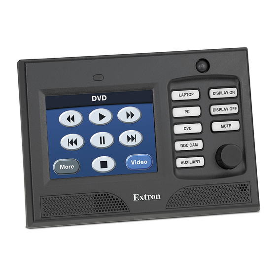
The Extron TLP 350MV is a wall-mounted TouchLink
IP Link
®
control systems.
Graphic and text objects are displayed on the screen. These objects have system control functions associated with them and the
touchpanel allows you to activate those functions.
Two BNC connectors allow the screen to be used to preview composite video or S-video.
NOTES:
The LAN output on the rear panel of the TLP 350MV must be connected to a network switch, hub, or router that is connected
•
to an Ethernet LAN or the Internet.
An Extron IP Link controller must also be connected to the same network (see
•
control processors).
The TLP 350MV is not compatible with the Extron IPL Pro or IPCP Pro control processors.
•
This guide provides basic instructions for experienced installers to mount and perform initial configuration on the TLP 350MV.
Complete instructions and reference material can be found in the TLP 350MV User Guide, which is available at www.extron.com.
TLP 350MV Front Panel Features
A A
B B
C C
TLP 350MV Front Panel (left) and Front Panel with Bezel Removed to Show Recessed Buttons (right).
Figure 1.
A
Light sensor — Monitors the level of ambient light and adjusts the screen brightness and button backlighting.
B
3.5 inch LCD screen — Provides a graphical user interface with a touch responsive display screen.
C
Speaker — Provides audible feedback.
D
Motion detector — Detects movement in front of the panel. When no motion has been detected for a user-defined period of
time, the unit goes into sleep mode, which shuts down the screen display and all the buttons become inactive. When motion is
detected, these functions are restored.
E
Eight backlit push-buttons — Can be configured to perform user-defined functions, using the Extron Global Configurator
software.
F
Encoder knob — Intended for volume control, but it can be configured for other functions.
Two buttons and an LED are recessed behind the bezel. Remove the bezel using the Extron
removal tool inserted into the tabs on the bottom of the panel, as shown in figure 2.
G
Menu button — Activates the on-screen
and setting the unit.
H
Reset button — Allows the unit to be reset in any of four different modes (see
Modes
on page 4).
I
Reset LED — Is visible only when the faceplate has been removed. It lights as an
indicator for the reset modes.
Panel that provides simple and versatile configuration and control for a range of
®
D D
E E
F F
(see page 3) for calibrating
www.extron.com
for a list of compatible
Reset
Remove Bezel
at Tabs
Removing the Bezel
Figure 2.
G G
H H
I I
®
Extron Removal Tool
1
Advertisement
Table of Contents

Related Manuals for Extron electronics TLP 350MV


Summary of Contents for Extron electronics TLP 350MV
- Page 1 Two BNC connectors allow the screen to be used to preview composite video or S-video. NOTES: The LAN output on the rear panel of the TLP 350MV must be connected to a network switch, hub, or router that is connected •...
- Page 2 TLP 350MV • Setup Guide (Continued) Mounting the TLP 350MV Decide where to mount the TLP 350MV and whether to use a 3-gang mud ring or a 3-gang UL-certified junction box. The mounting instructions are slightly different depending on your choice:...
-
Page 3: Setup Menu
Configuring the TLP 350MV (Initial Setup) Before use, the TLP 350MV must be configured using the on-screen menus. There are five different screens ( Main , Vol , Time , IP , and Vid ) that can be selected by pressing the appropriate button at the edge of the Main screen. There is also an Exit button at the bottom left corner of the screen for leaving the menus. -
Page 4: Reset Modes
Extron Web site. To get started using either program, refer to the TLP 350MV User Guide. Full instructions for the programs can be found in their help files, which can be opened from the Help menu of the programs.
Need help?
Do you have a question about the TLP 350MV and is the answer not in the manual?
Questions and answers