Advertisement
Quick Links
Advertisement

Related Manuals for Extreme Flight 60" Slick 580 ARF


Summary of Contents for Extreme Flight 60" Slick 580 ARF
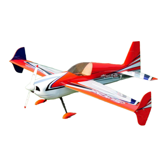
- Page 1 60" Slick 580 ARF Instruction Manual Copyright 2015 Extreme Flight RC...
- Page 2 THIS IS NOT A TOY! Serious injury, destruction of property, or even death may result from the misuse of this product. Extreme Flight RC is providing you, the consumer, with a very high quality model aircraft component kit, from which you, the consumer, will assemble a flying model.
- Page 3 Items needed for completion: Masking tape. Hobby knife with #11 blades. Thin and medium CA. We highly recommend Mercury M5T thin and M100XF medium formulas as well as the Mercury glue tips. 30 minute epoxy. Blue Loctite. ...
- Page 4 Tips for Success: 1. Before starting assembly, take a few minutes to read the entire instruction manual to familiarize yourself with the assembly process. 2. Note that this aircraft is covered using our printed covering technique. Your aircraft has been sealed with a gloss clearcoat. Due to climate changes, wrinkles may develop in the covering.
- Page 5 Let's begin! 1. Locate the 2 wing panels as well as the composite aileron control horns. Use a soldering iron or sharp hobby blade to remove the covering over the servo opening and the slot for the aileron horn. Make sure you are doing this on the bottom of the aileron! 2.
- Page 6 3. Flex the ailerons fully up and down, check for free action.
- Page 7 4. Making sure the aileron is properly aligned between the wing root and wing tip, hold the aileron fully deflected and apply a few drops of thin CA to each hinge. Flip the wing over and repeat. 5. Before installing the aileron servo, take a minute and apply some CA to the servo tray and the anti-rotation pins.
- Page 8 6. Before moving to the next step, it would be a good time to seal the hinge gap with a strip of Ultracote or Blenderm tape. Be sure to fully deflect the control surface when sealing the gap to allow for full deflection once the gap is sealed. Sealing the hinge gaps on your model improves control feel and response, but it is important that the seal not create too much drag, leading to poor servo performance.
- Page 9 7. Attach a 6” servo extension wire to the aileron servo, and make sure it is secured with tape or heat shrink or a lock. Use the manufacturer supplied mounting hardware to install the servo as shown. Electronically center the servo and install the second longest servo arm from the Dubro servo arm kit.
-
Page 10: Fuselage Assembly
Fuselage Assembly 8. Locate the 2 axles, 2 locking nuts, 2 wheels, 2 wheel collars and 2 wheel pants. Place the wheel on the axle and secure with the wheel collar. - Page 11 9. Place the threaded portion of the axle through the hole in the landing gear and attach the lock nut and washer onto the axle. NOTE: Note the LG has a tapered edge and a straight edge; make sure the straight edge faces the front. Slide the wheel pant into position over the axle and tighten the nut, making sure the wheel pant is positioned properly.
- Page 12 10. Secure the landing gear to the fuselage by inserting the 3mm bolt into a washer, through the carbon fiber gear and into the pre-installed blind nuts in the fuselage. Make sure to use a drop of blue Loctite on each bolt to prevent them from backing out.
- Page 13 12. Locate rudder and rudder pull-pull control horn as shown. Remove covering over slot in rudder for horn as shown. Glue brass tiller piece into rudder as shown. (Note: the tiller piece is the same part as is used for the end of the rudder pull-pull cables.) 13.
- Page 14 14. Check alignment of rudder hinges and slide rudder onto fuselage. Check for free swinging motion 45 degrees each way, and glue with thin CA glue as you did the aileron hinges. 15. Locate the hardware for the rudder pull-pull system as shown. Thread the ball links onto the brass ends as shown.
- Page 15 16. Using a piece of masking tape, tape the rudder so that it remains centered while you build the pull-pull cables. Screw the ball links and ends onto the rudder horn as shown, placing a washer on the ball-link side of the screw. Thread one of the brass tubes onto the pull-pull cable and loop the cable as shown.
- Page 16 17. Mount the rudder servo as shown. Assemble the pull-pull cable ends as you did on the runner end, as shown. The cables should be taught, but not so tight as to cause drag on the servo. 18. Remove covering over the horizontal stabilizer slot in the fuselage as shown.
- Page 17 19. Remove the covering over these openings in the fuselage, for the wing tube, wing pins, and aileron servo wires.
- Page 18 20. Insert the stabilizer into its slot and the carbon fiber wing tube into the fiberglass sleeve. Use a ruler to insure that the stabilizer is centered in its slot and compare the stabilizer to the wing tube to make sure it is properly aligned. Sand or shim the slot if necessary to ensure proper alignment.
- Page 19 21. Once satisfied with the alignment, glue the horizontal stab in place by applying CA along the joint between the stab and fuse. Make sure to apply CA to the top and bottom of the stab, being careful not to get CA on the covering. Allow to dry. 22.
- Page 20 23. Test fit the right side elevator, and make sure the elevators are perfectly aligned. Sand the slot in the right side elevator as necessary to make the elevators align perfectly. Once the alignment is perfect, remove the right elevator apply epoxy to the joiner and slot as shown.
- Page 21 24. Re-install the right elevator, check alignment again, check for free movement 50 degrees up and down, glue elevator hinges with thin CA. Tape the elevators to the stab as shown to ensure perfect alignment while the epoxy cures. 25. Remove the covering over the elevator control horn slot and elevator servo mount as shown.
- Page 22 26. Scuff the elevator horn and install with epoxy as on the ailerons and rudder. Build and install pushrod as shown. 27. Install a 24" servo extension wire on the elevator servo, install into the fuselage as shown.
- Page 23 28. Locate the carbon fiber tailwheel assembly in the hardware package. Secure the tailwheel bracket to the bottom rear of the fuselage with the provided wood screws, making sure the pivot point of the assembly is over the hinge line of the rudder. It is a good idea to remove the set screws from the tailwheel assembly and apply blue Loctite to them, then re-install.
- Page 24 29. Next prepare the Torque outrunner motor for mounting. First, slide the provided collar over the motor shaft and secure in place with the set screw. Place a drop of blue Loctite on the threads of the set screw so that it will not back out. 30.
- Page 25 31. Secure the prop adapter using the 4 socket head cap bolts. Blue Loctite should be applied to each bolt. 32. Using the backplate of the motor as a guide, mark and drill the 4 motor mounting holes in the firewall.
- Page 26 33. Install the motor with included 4mm screws and nuts. 34. Install the ESC to the side of the motor box using zip ties or Velcro to secure the ESC. Connect the wires of the ESC and motor together.
- Page 27 Mounting the Cowl 35. Tear 4 short pieces of blue painters tape from a roll. Place each piece of tape on the side of the fuselage so that each piece corresponds with one of the 4 cowl mounting tabs. Use a fine tipped marker to mark the location of the center of each mounting tab.
- Page 28 37. Use a 1/16" drill bit to drill a hole at the location of the dot on each piece of tape. 38. Remove the tape and secure the cowl with 4 of the included small wood screws that have the large heads.
- Page 29 39. Use a sharp hobby knife to remove the covering from the openings in the bottom of the fuselage to allow cooling air to exit the fuselage. 40. Mount your receiver in the fuselage. Use Velcro and a Velcro retention strap to secure your lipo battery.
- Page 31 42. Check your motor rotation direction, make sure your prop is tightened, verify that your battery if fully charged, and be certain your wing bolts are tight. Trimming your 60" Slick We highly recommend fine tuning your CG using the 45 degree line test. Fly the aircraft from left to right or right to left, whichever direction you are more comfortable with at 3/4 to full throttle.
- Page 32 People often ask me at trade shows how I get the planes to look so shiny, this is my secret. Thanks again for your purchase of the 3DHobbyShop 60" Slick 580 ARF. I hope you enjoy assembling and flying yours as much as I have mine. See you at the flying field! Chris Hinson Extreme Flight RC...
Need help?
Do you have a question about the 60" Slick 580 ARF and is the answer not in the manual?
Questions and answers