
Related Manuals for Extreme Flight 85" EDGE 540T 50cc ARF


Summary of Contents for Extreme Flight 85" EDGE 540T 50cc ARF
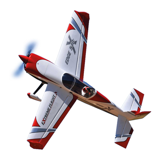
- Page 1 85" E DGE 540T 50cc A R F A ssembly Manual C opyright 2020 E xtreme F light R C www.modellmarkt24.ch www.modellmarkt24.ch...
- Page 2 C ongratulations on your purchase of the E xtreme F light R C 85" E dge 540T A R F ! Purpose built for the multitude of 50-60cc engines on the market, this brand new airframe is the perfect complement to these venerable power plants that have been neglected for far too long.
- Page 3 Please take a few moments to read this instruction manual before beginning assembly. W e have outlined a fast, clear and easy method to assemble this aircraft and familiarizing yourself with this process will aid in a quick, easy build. Please read the following paragraph before beginning assembly of your aircraft! T HIS IS NOT A T OY !
- Page 4 A few tips to ensure success 1. W e are very pleased with the level of craftsmanship displayed by the builders in our factory. T hrough hundreds of grueling test flights containing maneuvers that no aircraft should be subjected to, our prototypes have remained rigid and completely airworthy.
- Page 5 Since the 85" E dge 540T (and most of our other giant scale models) now come pre-hinged and the hinge gaps sealed, the most time consuming task of the assembly process has been eliminated. T his leaves a very minimal amount of gluing for the assembler, which consists of installing the composite control horns in the ailerons, elevators and rudder, with only the rudder hinges needing to be glued.
- Page 6 3. Scuff the portion of the horns that will be inserted into the elevator with sandpaper. 4. L ocate your epoxy, mixing cup, an old pushrod to stir with and a length of nylon cable tie to apply the epoxy. W e have used Pacer 30 minute Z -poxy for over 2 decades with excellent results and zero bond failures and we highly recommend this product.
- Page 7 5. Mix a generous batch of epoxy being careful to use equal parts resin and hardener. 6. Use the nylon cable tie to apply epoxy to the slots and thoroughly coat the control horns on both sides of each horn. www.modellmarkt24.ch www.modellmarkt24.ch...
- Page 8 7. Insert the control horns into the slots and ensure that the horns are properly seated against the base plate and the base plate is flush against the control surface. www.modellmarkt24.ch www.modellmarkt24.ch...
- Page 9 8. W ipe away the excess epoxy with a paper towel soaked in denatured alcohol, making sure to do a good job of cleaning the area. Insert a 3mm bolt and ball link into position and confirm proper alignment before the epoxy sets. www.modellmarkt24.ch www.modellmarkt24.ch...
- Page 10 9. R epeat this process for the other stab half, the aileron control horns and the rudder control horns. ***PL E A SE NOT E *** pull-pull rudder actuation with the rudder servo mounted in the rudder tray under the canopy is recommended for lightweight 50cc engines in order to achieve proper balance. If using a heavier 60cc or electric motor setup with large 12S L iPo batteries the rudder servo may be mounted in the rear of the fuselage.
- Page 11 www.modellmarkt24.ch www.modellmarkt24.ch...
- Page 12 10. A ssemble and install the servo mounting grommets. C onnect an E F 20 A W G servo extension to each aileron servo lead (secure with heat shrink tubing or an E F Servo Safety C lip) and install the elevator and aileron servos in their designated locations.
-
Page 13: F Uselage A Ssembly
F uselage A ssembly 12. W e’ ll begin by installing the landing gear. L ocate the carbon fiber main landing gear, 4-4mm bolts, lock nuts and washers. Insert the gear into the slot on the bottom of the fuselage and center it in the slot. - Page 14 13. T he landing gear fairings add a nice scale touch to the aircraft. Slide the fairing onto the gear and up against the fuselage. Secure the fairing to the gear with " Goop" silicon glue. Use blue painters tape to secure the fairings until the adhesive sets.
- Page 15 Use your rotary tool and a grinding bit or a file to create a flat spot on the axle for the wheel collar and wheel pant support set screws to seat against. A ttach the aluminum axle support to the plywood spacer with the provided wood screws.
- Page 16 17. Slide the wheel pants into position and secure with 2 3mm bolts and washers inserted through the carbon gear and into the blind nuts in the wheel pants. Be sure to use thread lock on the bolts! Pull the pant back from the plywood support block and run a bead of E poxy on the plywood surface to adhere the block to the wheel pant wall.
- Page 17 18. Next let’ s install the rudder onto the fuselage. Glue the hinges into the rudder first with epoxy and allow to cure. Use a pushrod to apply epoxy to the holes in the rudder post and push the rudder into position and wipe away any excess epoxy with a paper towel and denatured alcohol.
- Page 18 www.modellmarkt24.ch www.modellmarkt24.ch...
- Page 19 21. T he distance from the front face of the motor box to the motor drive washer is 172mm or 6.8 inches (this is the length of the DL E -61, the longest of the engines recommended). Because the DA -50 is the recommended motor we have included a set of machined aluminum standoffs to be used in conjunction with the stock 2.5"...
- Page 20 ***Please note that we removed the laser scribed panels in the F 1 former in our electric powered airframe to allow cooling air to reach the batteries*** 23. T here is a hole in the bottom of the motorbox to mount your throttle servo. T his location corresponds to the throttle arm on most single cylinder engines provides a straight shot from the servo arm to the throttle arm.
- Page 21 24. If using an electric motor we recommend mounting the E SC to the bottom of the motorbox either with screws, nylon cable ties or V elcro straps. 25. If using a lightweight 50cc engine like the DA -50 mount your rudder servo in the servo tray under the canopy using the manufacturer supplied mounting hardware.
- Page 22 www.modellmarkt24.ch www.modellmarkt24.ch...
- Page 23 26. If using a 60cc engine or large electric motor with high capacity L iPo batteries mount the rudder servo in the provided location in the rear of the fuselage with the output spline mounted toward the rear of the aircraft. Y ou will need to mount your rudder linkage to the interior side of the servo arm for sufficient clearance as shown.
- Page 24 27. If you plan to keep your stabs attached to the fuselage during transport then a 36" 20 A wg servo extension is long enough. If you plan to remove the stabs you will need to use a 48" extension. Secure the extension to the elevator servo lead with an E F Servo Safety C lip or heat shrink tubing.
- Page 25 29. If using a 50-60cc gas engine install a F lowmaster 17 ounce tank onto the tank tray and plumb with E F F lowmaster Blue F uel L ine. T here is a laser cut opening to accept an E F F uel Dot as well. T he following picture shows the location of our tank, batteries and receiver which provided the ideal center of gravity.
- Page 26 31. T here is a set of clear plastic baffles included to be used for electric setups to direct air over the motor. C ut and trim the baffles and glue to the cowl inlets with Goop or medium C A . 32.
- Page 27 www.modellmarkt24.ch www.modellmarkt24.ch...
- Page 28 33. Install your choice of prop (if using the DA -50 we highly recommend the F alcon 23x8 C arbon F iber prop) and E xtreme F light 4" carbon fiber spinner. W e have spinners available that are painted to match these color schemes.
- Page 29 36. Included with your E dge are a set of Side F orce Generators (SF Gs) along with 2 clear spacers to be installed between the SF Gs and wing tip to prevent them from interfering with aileron movement. T hey are to be installed using the supplied white thumb screws threaded through the holes in the SF G, through the clear spacer and into the pre-installed blind nuts in the wing tip.
- Page 30 C ontrol surface throws I highly recommend that you purchase a throw meter that measures in degrees. T here are several units available commercially. T hese units are a great aid in set-up and definitely beat the “that looks about right”...
Need help?
Do you have a question about the 85" EDGE 540T 50cc ARF and is the answer not in the manual?
Questions and answers