Advertisement
Quick Links
Advertisement

Related Manuals for Extreme Flight EDGE 540T


Summary of Contents for Extreme Flight EDGE 540T
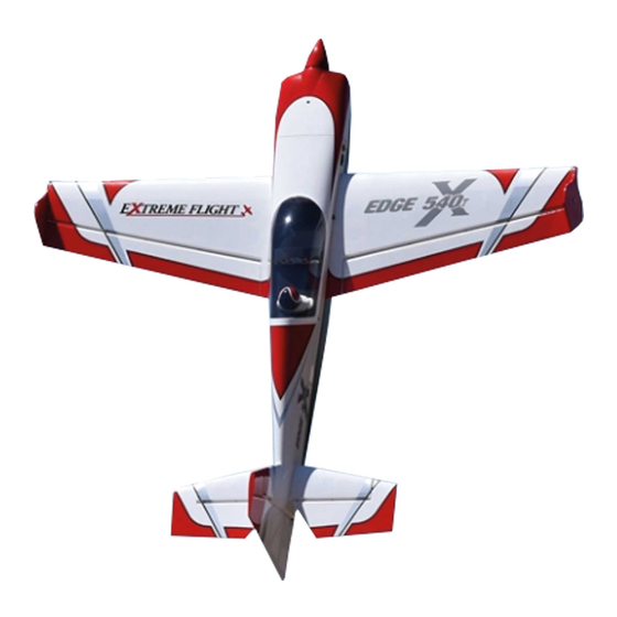
- Page 1 EDGE 540T ELECTRIC ARF Instruction Manual ©Copyright 2006 EXTREME FLIGHT RC, Ltd.
- Page 2 The Edge 540T can truly be assembled in an evening-buy it one day, fly it the next! As with all Extreme Flight RC airplanes, the proof is in the flying! The Edge 540T flies precision aerobatics remarkably well and allows you to practice your IMAC sequence almost anywhere.
- Page 3 Tips for Success-Please read before beginning assembly!!! 1. Read the instruction manual thoroughly before starting assembly. 2. We are very pleased with the level of craftsmanship exhibited by the workers in our factory. However, these are mass produced models. As with any ARF, take a few minutes to go over the model and add CA to high stress areas or any joints that appear to need more glue.
- Page 4 Wing assembly 1. Locate a wing panel. Check to see that all hinges are centered between the wing and aileron. Hold the aileron fully deflected and apply a drop of thin CA to each hinge. Flip the wing over and repeat. 2.
- Page 5 3. Locate the composite aileron control horn, aileron pushrod with z-bend and ez- connector. Remove the covering over the mounting hole for the control horn with your #11 blade. Scuff the part of the control horn that will glue into the aileron slot with fine sandpaper.
- Page 6 4. Repeat this procedure for the other wing. That’s it! You are done with the wings! Fuselage Assembly 5. Lets mount the landing gear first. Locate the aluminum landing gear, (2) 3mm machine screws, (2) park flyer axles, (2) nylon insert lock nuts, (2) wheel collars, (2) wheel pants, (2) wheels and (2) plywood squares from the hardware package.
- Page 7 6. Place a drop of blue Loctite on the threads of the 3mm landing gear mounting bolts and insert them through the landing gear and into the pre-installed blind nuts in the landing gear plate.
- Page 8 7. Locate the motor box. Insert the tabs on the motor box into the slots in the F1 former. Use medium CA to secure the motor box to the F1 former. Make sure to apply CA to all joints on both sides of the F1 former as well as all joints in the motor box.
- Page 9 9. Use scissors to remove the air scoops from the plastic sheet. 10. Use medium CA to secure the scoops to the side of the motor box as shown in the photo. 11. Locate the horizontal stab. Trial fit the stab into its slot in the rear of the fuselage and use a felt tipped marker to mark where the covering will need to be removed from the horizontal stab.
- Page 10 12. Insert the elevator into the slot in the rear fuselage side. It must be inserted upside down with the counter balances facing the rear of the plane, then it can be rotated into the proper position. Please see photo for detail. 13.
- Page 11 17. Locate the elevator control horn and glue in place with medium CA or epoxy. Make sure to scuff the surface of the control horn before gluing. Use a #11 blade to remove the covering from the elevator servo slot and install the servo using the manufacturer supplied mounting hardware.
- Page 12 20. Drill a small hole in the bottom of the rudder and insert the pre-bent tailwheel wire into place. Use a piece of strapping tape to secure the tailwheel wire to the rudder as shown. Slide the tailwheel onto the wire and retain with the small wheel collar.
- Page 13 21. Use the supplied 3mm bolts and washers to mount the motor to the mounting plate. Put a drop of blue Loctite on the mounting bolts, place a washer on the bolt and insert through the front of the motor mounting plate and into the threaded holes in the face of the motor.
- Page 14 23. Soak the cowl mounting tabs with thin CA 24. Place the canopy/hatch in place on the fuselage and make sure it is positioned properly. Slide the cowling into place. The rear of the cowl should be flush with the rear of the F1 former. Make sure the prop shaft is centered in the cowl opening.
- Page 15 29. Remove the covering from the bottom of the fuselage as shown to allow cooling air to escape from the fuselage. This concludes the assembly of the Edge 540T.
- Page 16 Radio Set-up and flight tips. CG range for the Edge 540T is from 3”- 3.5” from the leading edge of the wing measured at the wing root. Correct CG should be easy to achieve by moving the battery along the length of the battery tray. Adjust to fit your flying style.
Need help?
Do you have a question about the EDGE 540T and is the answer not in the manual?
Questions and answers