Advertisement
Quick Links
Advertisement

Related Manuals for Extreme Flight 91" EXTRA 300EXP ARF


Summary of Contents for Extreme Flight 91" EXTRA 300EXP ARF
- Page 1 91" EXTRA 300EXP Assembly Manual Copyright 2012 Extreme Flight RC 1 ...
- Page 2 Serious injury, destruction of property, or even death may result from the misuse of this product. Extreme Flight RC is providing you, the consumer with a very high quality model aircraft component kit, from which you, the consumer, will assemble a flying model. It is beyond our control to monitor the finished aircraft you produce.
- Page 3 A few tips to ensure success 1. We are very pleased with the level of craftsmanship displayed by the builders in our factory. Through hundreds of grueling test flights containing maneuvers that no aircraft should be subjected to, our prototypes have remained rigid and completely airworthy. Having said that, it is impossible for us to inspect every glue joint in the aircraft.
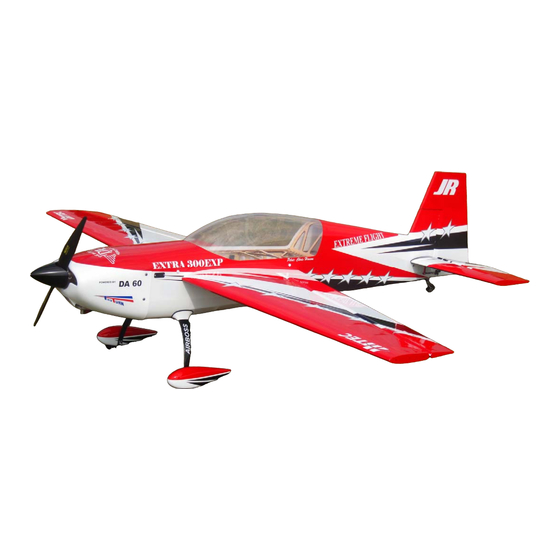
- Page 4 Congratulations on your purchase of the Extreme Flight RC 91" Extra 300EXP ARF! Designed specifically to handle the high G loads of Xtreme Aerobatics (XA), Freestyle routines, aggressive 3D maneuvers and precision aerobatics, the Extra was born of the desire to meet the demands of today's top ultra-aggressive pilots.
-
Page 5: Elevator Assembly
Elevator assembly 1. Locate the horizontal stabilizer/elevator assemblies as well as the composite control horns and base plates from the elevator hardware package. Use a sharp #11 blade to make a cut in the covering over the 2 slots for the elevator control horns on the bottom of the elevator surface. Double check to make sure you are cutting into the bottom of the elevator. - Page 6 3. Remove the horn assembly and use your #11 blade to remove the covering from inside the ink line you traced around the control horn base. Wipe away the ink line with a paper towel soaked in denatured alcohol. Scuff the portion of the horns that will be inserted into the elevator with sandpaper. Apply 30 minute epoxy to the slots and thoroughly coat the horns and base plate bottom.
- Page 7 7 ...
- Page 8 8 ...
- Page 9 4. In this step I will outline the procedure we use to install the hinges. There are several ways to do this and several adhesives you can use. We will describe the way we do it, as this method has proven itself over many years of model building.
- Page 10 10 ...
- Page 11 5. After the hinges have dried thoroughly, pull on them to make sure they are properly installed. The hinges will probably feel a little stiff as it is almost impossible to get all of the glue out of the knuckle joint.
- Page 12 7. Install the elevator servo inside the stab using the manufacturer supplied mounting hardware with the output shaft toward the front of the stab. It will be easier to electronically center the servo and confirm proper servo arm installation before screwing the servo into position, although you will still need to remove the arm to install the servo.
- Page 13 8. Locate 2 ball links and a titanium turnbuckle pushrod. Thread the ball links onto the pushrod and install using the supplied 3mm bolts, nuts and washers as shown in the picture. 9. Before you set aside the stabs take a moment with your covering iron and go over all of the seams with a medium heat setting, paying special attention to the ends of thin trim stripes.
-
Page 14: Wing Assembly
Wing Assembly 10. Remove the aileron from the wing panel. Locate the 2 slots for the control horns and remove the covering from the slots with a sharp #11 blade. Follow the same procedure as outlined previously for the elevator to install the control horns into the control surface and hinge the wing. Repeat this procedure for the other wing. - Page 15 (Aileron horn has been painted black in the following picture) 11. Locate the aileron servo mount and remove the covering from this area. Use a sealing iron to seal the edges of the covering to the sides of the servo opening. Take a few minutes to apply some CA to the joints of the servo mount and the ribs.
- Page 16 13. Before beginning the next assembly process, take a few minutes with your sealing iron on a medium heat setting and go over all seams, paying special attention to thin trim stripes and the seam at the leading edge of the wing. If there are wrinkles in the covering on the leading edge sheeting use a heat gun with a 100% cotton t-shirt to remove them and prevent digging into the wood with an iron.
- Page 17 17 ...
-
Page 18: Fuselage Assembly
Fuselage Assembly 15. We’ll begin by installing the landing gear. Locate the carbon fiber main landing gear, 4-4mm bolts, lock nuts and washers. Insert the gear into the slot on the bottom of the fuselage and center it in the slot. Secure the landing gear with 4 4mm bolts, washers and nylon insert lock nuts by inserting the bolts and washers into the pre-drilled holes in the aluminum gear mounts inside the fuselage with a long T-handle wrench. - Page 19 19 ...
- Page 20 17. Locate the 2 axles, 2 locking nuts, 2 wheels, 4 wheel collars and 2 wheel pants from the hardware package. Place the wheel onto the axle and secure with 2 wheel collars. Place the threaded portion of the axle through the hole in the landing gear, place a washer onto the axle and secure the axle with a locking nut.
- Page 21 19. Next let’s install the rudder onto the fuselage. As you did with the ailerons and elevators, glue the hinges into the rudder first with epoxy and allow to cure. Use a pushrod to apply epoxy to the holes in the rudder post and push the rudder into position and wipe away any excess epoxy with a paper towel and denatured alcohol.
- Page 22 21. Drill a hole in the bottom of the rudder to fit the shank of the included white 2mm ball link 3.5 inches from the rudder hinge line. 22 ...
- Page 23 22. Glue the ball link into the bottom of the rudder using epoxy. Allow a small amount of epoxy to pool around the ball link shank for best results. 23. Slide the tiller arm into the ball link and secure the tailwheel assembly to the rear bottom of the fuselage with the supplied 3mm bolts inserted through the carbon tailwheel assembly and into the pre- installed blind nuts in the bottom of the fuselage.
- Page 24 24. Next let’s install the engine. We have made this process very easy. The centering marks have been scribed into the front of the firewall with a laser. Download the manufacturer's mounting template and tape it to the front of the engine box, making sure to align the horizontal and vertical lines on the template with the laser scribed lines on the firewall.
- Page 25 26. If you plan to use a tuned pipe remove the covering from the bottom of the pipe tunnel on the underside of the fuselage. Shown in the photo is a KS-1060 mounted using a KS Comfort Mount. This makes for a very simple pipe installation. For the DA-60 you will need a 25mm drop wrap around header.
- Page 26 27. Mount your rudder servo in the servo tray under the canopy using the manufacturer supplied mounting hardware. For proper geometry use the SWB 4” offset rudder arm or a similar unit. 26 ...
- Page 27 28. Now is the time to install the pull-pull rudder cables. Look at the rear of the fuselage just below the horizontal stabilizer location and you will find the location of the pull-pull cable exit slots. Use a sharp hobby knife to pierce the covering in this location on each side of the fuselage. 29.
- Page 28 31. Slide both stab/elevator assemblies onto the carbon fiber mounting tube and secure with 2 3mm bolts inserted through a washer and the mounting tabs and into the corresponding blind nuts already installed in the fuselage. Be sure to use a drop of blue Loctite on all bolts!!! 32.
- Page 29 33. Assemble and install your choice of gas tank in front of the wing tube socket using nylon cable ties through the mounting tabs and around the tank. I suggest using a piece of foam under the tank. We have had great success using the pre-assembled 4Titude Tanks. 34.
- Page 30 37. Included with your Extra are a set of Side Force Generators (SFGs) along with 2 clear spacers to be installed between the SFGs and wing tip to prevent them from interfering with aileron movement. They are to be installed using the supplied white thumb screws threaded through the holes in the SFG, through the clear spacer and into the pre-installed blind nuts in the wing tip.
- Page 31 60-70% exponential. Again, this is just a starting point. Adjust to your liking. Thanks again for your purchase of the Extreme Flight RC 91" Extra 300EXP ARF. I hope you enjoy assembling and flying yours as much as I have mine.
Need help?
Do you have a question about the 91" EXTRA 300EXP ARF and is the answer not in the manual?
Questions and answers