
Related Manuals for Extreme Flight Edge 540T


Summary of Contents for Extreme Flight Edge 540T
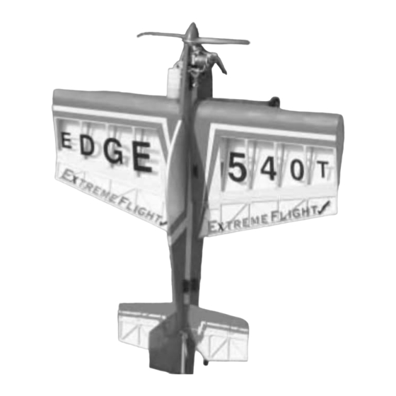
- Page 2 Thank you for your purchase of the Extreme Flight RC .40 Edge 540T Funfly. Please take a few moments to read this instruction manual before beginning assembly. We have outlined a fast, clear and easy method to assemble this aircraft and familiarizing yourself with this process will aid in a quick, easy build.
- Page 3 1. Locate fuselage and remove the covering from the throttle servo mounting hole, the wing slot, the rudder and elevator servo mounting holes and the elevator slot using a sharp #11 blade. 2. Locate the landing gear components including 4 screws, 8 washers, and 6 nylon insert locknuts. Assemble the axle/wheel assembly first.
- Page 4 4. Locate tailwheel components including tailwheel wire, tailwheel, wheel collar, and plywood trian- gle. File a flat area onto the wire where the wheel collar will reside. Place the tailwheel onto the wire, then the wheel collar. Use thread lock compound on the retaining screw and tighten onto the flat area.
- Page 5 6. Insert the wing into the wing slot. Using the same criteria as used for the stab, center the wing and check for proper alignment. Again, using a fine tip marker, make several positioning marks to aid with alignment when gluing the wing in place. Remove the wing and remove a strip of covering to allow for a wood to wood bond between the wing and fuselage.
- Page 6 8. Next we will install the rudder and elevator servos. Use the manufacturer supplied servo hard- ware to mount the servos in the rear of the fuselage. The elevator servo mounts in the top hole, the rudder servo in the bottom. Use a good quality standard servo with a ball bearing supported output shaft.
- Page 7 10. Use a #11 blade to cut a small slit just below the leading edge of the left wing in order to pass the throttle servo lead into the radio compartment. 11. Locate a nylon control horn and backplate, two small machine screws, one clevis, one pushrod, one pushrod keeper and one length of heat shrink tubing from the hardware package.
- Page 8 12. Follow the same procedure as oulined in the previous step to determine the proper location for the aileron control horns and consruct the aileron pushrods. Center the ailerons to the airfoil of the wing. 13. Wrap your airborne battery pack in foam and install it into the opening in the servo tray in the wing opposite the engine.
- Page 9 15. Use a paper towel and some denatured alcohol to thoroughly clean the bottom of the fuselage. Locate the strip of blue Oracover and iron it in place over the servo wire channel. Be sure to seal the edges well using a medium heat setting. 16.
- Page 10 18. Locate the servo bay hatches and position them in place. Use a 1/16th drill bit to drill through the hatches and the plywood mounting tabs in each of the four corners. Secure the hatches with the small wood screws provided in the hardware package. Be sure to drill a hole in the hatch to allow the antenna to pass through.
- Page 11 Take your time and devote the first several flights to properly trimming your aircraft and you will be reward- ed with an incredible flying 3D machine. Thanks again for your purchase of the Extreme Flight RC .40 Edge 540T Funfly. See you at the flying field!
Need help?
Do you have a question about the Edge 540T and is the answer not in the manual?
Questions and answers