Table of Contents
Advertisement
Quick Links
INSTRUCTIONS
A radio-controlled model is not a toy and is not intended for persons under 16 years old. Keep
this kit out of the reach of younger children, as it contains parts that could be dangerous. A radio-
controlled model is capable of causing serious bodily injury and property damage. It is the buyer's
responsibility to assemble this aircraft correctly and to properly install the motor, radio, and all other
equipment. Test and fly the finished model only in the presence and with the assistance of another
experienced R/C flyer. The model must always be operated and flown using great care and common
sense, as well as in accordance with the Safety Code of the Academy of Model Aeronautics
(www.modelaircraft.org). We suggest you join the AMA and become properly insured prior to flying
this model. Also, consult with the AMA or your local hobby dealer to find an experienced instructor in
your area. Per the Federal Communications Commission, you are required to use only those radio fre-
quencies specified "for Model Aircraft."
Carl Goldberg Products has inspected and certified the components of this aircraft. The company urges the buyer to perform his
own inspection, prior to assembly, and to immediately request a replacement of any parts he believes to be defective for their
intended use. The company warrants replacement of any such components, provided the buyer requests such replacement with-
in a period of 90 days from the date of purchase and provided the defective part is returned, if so requested by the company.
No other warranty, expressed or implied, is made by the company with respect to this kit. The buyer acknowledges and under-
stands that it is his responsibility to carefully assemble the finished flying model airplane and to fly it safely. The buyer hereby
assumes full responsibility for the risk and all liability for personal or property damage or injury arising out of the buyer's use of the
components of this kit.
CARL GOLDBERG PRODUCTS, LTD.
P.O. Box 88 Oakwood GA 30566 Phone #678-450-0085 Fax # 770-532-2163 www.carlgoldbergproducts.com
WARNING
LIMITED WARRANTY
© Copyright 2004 Carl Goldberg Products LTD
1
TM
Advertisement
Table of Contents

Related Manuals for Carl Goldberg Products Sr. Falcon


Summary of Contents for Carl Goldberg Products Sr. Falcon
- Page 1 LIMITED WARRANTY Carl Goldberg Products has inspected and certified the components of this aircraft. The company urges the buyer to perform his own inspection, prior to assembly, and to immediately request a replacement of any parts he believes to be defective for their intended use.
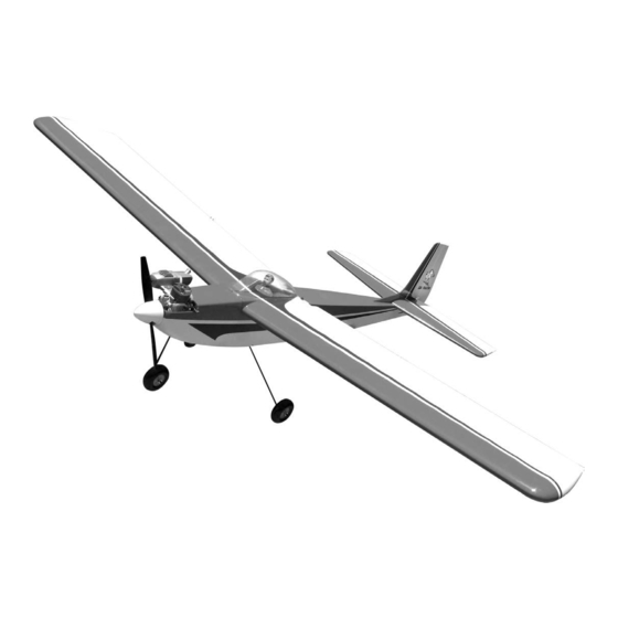
- Page 2 Hardware List Parts List (Not Shown) (Items Shown) 1. Fuselage 2. Wings with Ailerons 3. Stab with Elevators 4. Fin 5. Rudder 6. Tank Hatch 7. Dihedral Brace 8. Fuel Tank with hardware 9. Main Landing Gear 10. Nose Gear 11.
- Page 3 USING THIS INSTRUCTION MANUAL ITEMS NEEDED TO COMPLETE THIS AIRCRAFT Before you begin assembling your Sr. falcon Mark II ARF, RADIO GUIDANCE SYSTEM (4 CHANNEL take some time to read through this entire instruction book. MINIMUM REQUIRED, 5 STANDARD SER-...
- Page 4 COVERING PUSHRODS: Obviously, pushrods should be installed to operate freely, so that they place no load on the servo. The Sr.Falcon ARF is covered in a premium polyester film Using a servo's power to move a tight rod or heavy surface chosen by many of the world's top flyers for its beauty, by force increases the battery drain, shortens the electron- toughness, and ease of application and repair.
-
Page 5: Wing Assembly & Installation
WING ASSEMBLY & INSTALLATION Slide the aileron toward the wing until no gap AILERON INSTALLATION remains between the aileron and the wing. Carefully check the alignment of the aileron. There should be about 1/32" on both ends. When satisfied with the alignment, remove the straight pins, being sure to keep the aileron tight to the wing. -
Page 6: Aileron Servo Installation
Place additional tape at several locations across the center seam of the wing, so that the halves stay firmly together while the epoxy sets. Fit the wing on the fuselage and install the wing bolts to make sure the dowels on the front and the wing bolts at the rear align. -
Page 7: Aileron Control Horn Installation
Gently pull the string out of the aileron servo hole and tie it or tape it to the servo wire. From the bottom of the wing remove the cov- ering over the hole that is next to the center rib. With the aileron servo arm in place, make a Pull the servo wire towards the center of the mark at a 90º... - Page 8 Mark wire Make sure the aileron is in neutral (level) position, mark where the wire meets the hole on the servo arm. Remove the wire and cut it about 1/2" beyond the mark. Insert the fin in the slot in the top of the stab. Bend the wire 90 degrees up at the mark you just made.
- Page 9 Remove covewring Remove the covering on the stab saddle of the fuselage so the stab will glue to bare wood. Bolt the wing in place and epoxy the stab-fin structure to the fuselage. Epoxy the fin to the stab making sure it is perpendicular.
- Page 10 Remove the rudder and align the control horn on the mark you made. Make sure the holes Insert one gear leg in the hole in the bottom of for the clevis are over the hinge line. the fuselage. Mount the control horn using the 1.5mm screws just as you did on the ailerons.
-
Page 11: Nosegear Installation
NOSEGEAR INSTALLATION OLLECT THE FOLLOWING PARTS Nosegear strut (3) Wheel Collars and set screws (1) Wheel (1) Nosegear steering arm (1) 1.5mm x 43 cm wire and tube (1) EZ connector and screw (1) Nylon Swivel Keeper Slide the steering arm on the top of the nosegear strut. -
Page 12: Engine Installation
Left side of the fuselage Install the rudder servo as shown. Once you have your motor mount then place Slide the nose gear wire into the hole in the the mount into the front of the fuselage. EZ connector. Make sure that the smaller side beam is on Remount the servo arm and center the servo the left side of the fuselage. - Page 13 Install the motor on the plate using the 4mm blind nuts and bolts. Mark the location of the engine mounting holes. Also at this time mark the location of where the throttle pushrod should exit the firewall. Remove the engine and the motor mount plate.
-
Page 14: Throttle Push Rod Installation
Hole Slide the throttle pushrod tubing into the hole in the firewall that you drilled earlier. Push the tube through the fuel tank compart- ment and through the small hole on the side of the former. Remount the motor to the plate. If you wish to have a break away motor mount you can use four #6 X 3/4”... -
Page 15: Push Rod Installation
Slide the heat shrink tubing over the pushrod PUSH ROD INSTALLATION and shrink using a blow drier. Glue the tubing to the wood pushrod using thin CA glue. This finishes one end of the elevator pushrod. NON THREADED WIRE 1/2” Collect the following parts (2) 19”... -
Page 16: Rudder Pushrod
RUDDER PUSHROD Insert the wire into the hole in the wood pushrod and push down into the groove. Glue the wire to the wood pushrod using Remove the metal clevis from the end of a 1.5 medium CA glue. x 25cm wire. Threaded end 8”... - Page 17 Tape the rudder so that it stays in the neutral position. Align the servo arm so that it is sitting at 90 degrees to the servo. Mark the location where the pushrod wire meets the outer hole of the servo arm. Bring the elevator pushrod out the right side and the rudder pushrod out the left side.
-
Page 18: Fuel Tank Assembly
FUEL TANK ASSEMBLY ATHER THE FOLLOWING ITEMS FUEL TANK RUBBER TANK STOPPER Install the 4mm silicone tube to the short CLUNK brass tube and install the clunk to the other (1) 3 MM X MM SCREW end of the silicone tube. This is the fuel pick- CAP WASHER LARGE up and must be free to “flop”... -
Page 19: Installing Fuel Tank
INSTALLING FUEL TANK RADIO SWITCH, RECEIVER, BATTERY We mounted the receiver and battery in front of the servo tray. Depending on what engine you use, you might need to move the battery pack forward in to the fuel tank compartment. Insert the fuel tank through the wing saddle area and feed the fuel lines through the hole in the firewall. - Page 20 Using artist's acrylics or modeling enamels, BALANCING paint the pilot to suit your fancy. WARNING: Do not use lacquer-based paints, which will IMPORTANT: NEVER NEGLECT THIS STEP WITH destroy the plastic. ANY AIRPLANE. If you try to fly a plane with the When dry, CA glue the pilot in place on the balance point behind the recommended range, cockpit.
- Page 21 You can then work your way up to the higher set- result of practice. The crisp, graceful movements tings. The settings for the SR. FALCON ARF are: come from the pilot's willingness to do and do it again. HIGH Don't give up;...
Need help?
Do you have a question about the Sr. Falcon and is the answer not in the manual?
Questions and answers
Do you sell snr fancon decal sheets and cockpits. Have an old model I **** rerurbizhing