Table of Contents
Advertisement
Quick Links
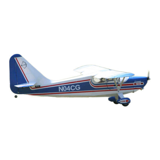
Introduced in 1947, The Stinson 108 Flying Station Wagon was ahead of its time. The slo-
gans "My airplane works for a living" and "America's No. 1 Utility Plane" was easy to understand as
the Flying Station Wagon seated four along with 100 pounds cargo, and cruised at 130mph.
With Carl Goldberg's Stinson 108 ARF Flying Station Wagon you'll experience this classy air-
plane like never before. Relaxing predictable slow flight is like second nature. Flaps with duel servo
control allow for extremely slow flight & easy landings. When you want something extra, this capa-
ble aerobatic beauty features dual elevator servos, independent aileron servos, and airfoiled tail
group to take advantage of all your skill.
A radio-controlled model is not a toy and is not intended for persons under 16 years old. Keep
this kit out of the reach of younger children, as it contains parts that could be dangerous. A radio-
controlled model is capable of causing serious bodily injury and property damage. It is the buyer's
responsibility to assemble this aircraft correctly and to properly install the motor, radio, and all other
equipment. Test and fly the finished model only in the presence and with the assistance of another
experienced R/C flyer. The model must always be operated and flown using great care and common
sense, as well as in accordance with the Safety Code of the Academy of Model Aeronautics (5151
Memorial Drive, Muncie, IN 47302, 1-800-435-9262). We suggest you join the AMA and become prop-
erly insured prior to flying this model. Also, consult with the AMA or your local hobby dealer to find an
experienced instructor in your area. Per the Federal Communications Commission, you are required
to use only those radio frequencies specified "for Model Aircraft."
Carl Goldberg Products, Ltd. has inspected and certified the components of this aircraft. The company urges the buyer to per-
form his own inspection, prior to assembly, and to immediately request a replacement of any parts he believes to be defective for
their intended use. The company warrants replacement of any such components, provided the buyer requests such replacement
within a period of 90 days from the date of purchase and provided the defective part is returned, if so requested by the company.
No other warranty, expressed or implied, is made by the company with respect to this kit. The buyer acknowledges and under-
stands that it is his responsibility to carefully assemble the finished flying model airplane and to fly it safely. The buyer hereby
assumes full responsibility for the risk and all liability for personal or property damage or injury arising out of the buyer's use of the
components of this kit.
CARL GOLDBERG PRODUCTS, LTD.
© Copyright 2004
P.O. Box 88 Oakwood GA 30566 Phone #678-450-0085 Fax # 770-53-63 www.carlgoldbergproducts.com
WARNING
LIMITED WARRANTY
Advertisement
Table of Contents

Related Manuals for Carl Goldberg Products Stinson 108 ARF


Summary of Contents for Carl Goldberg Products Stinson 108 ARF
- Page 1 LIMITED WARRANTY Carl Goldberg Products, Ltd. has inspected and certified the components of this aircraft. The company urges the buyer to per- form his own inspection, prior to assembly, and to immediately request a replacement of any parts he believes to be defective for their intended use.
- Page 2 INTRODUCTION COVERING USING THIS INSTRUCTION MANUAL The Stinson ARF is covered in a premium polyester film Before you begin assembling your Stinson ARF, take chosen by many of the world's top flyers for its beauty, some time to read through this entire instruction book. It toughness, and ease of application and repair.
- Page 3 ITEMS NEEDED TO COMPLETE THIS AIRCRAFT TOOLS AND SUPPLIES FOR ASSEMBLY RADIO GUIDANCE SYSTEM (6 CHANNEL MODELING OR UTILITY KNIFE MINIMUM REQUIRED WITH 8 SERVOS) WORK SURFACE (24" X70") 12” AILERON SERVO EXTENSION WIRES ELECTRIC DRILL 24” ELEVATOR SERVO EXTENSION 1/16”, 3/32”,1/8", 3/16”, 5/32”, 1/4”, 5/64”...
-
Page 4: Wing Assembly
WING ASSEMBLY Select the aileron and flap for the wing on AILERON INSTALLATION which you are working on and insert the exposed half of each hinge into the aileron slots. Slide the aileron toward the wing until no gap remains between the aileron and the wing. Carefully check the alignment of the aileron. -
Page 5: Aileron Servo Installation
AILERON SERVO INSTALLATION Note: The following pictures may not exactly match the hardware you are using. Always check the radio manufacturer's instructions when installing radio equipment. IMPO RTANT! To ensure that any connections locat- ed inside the wing will not come loose, either when the wires are pulled, or during flying, always tape them securely together with electrical tape. -
Page 6: Aileron Control Horn Installation
HINT: Drill the hole from the bottom half way. AILERON CONTROL HORN INSTALLATION Then measure and mark the top of the aileron and drill down to the hole from the top of the aileron. Collect the following items (4) Metal Clevis (4) 4-40 Hex Nut (4) 2-56 x 4-7/8"... -
Page 7: Tail Construction
TAIL CONSTRUCTION STAB INSTALLATION Collect the following items (2) Right & left Stab (1) 10mm x 182mm front stabilizer tube (1) 10mm x 312mm Rear Stabilizer tube (2) 4-40 x 3/8 Socket head screw Take three hinges and, as with the aileron hinge installation, insert the hinge into the ele- vator, using straight pins to ensure the hinge stays centered between the stabilizer and the... - Page 8 Using a 9/64" drill bit, make a hole in the ele- vator through to the top side. Insert the 6-32 x 2” screw from the top through the elevator. At the rear of the fuselage just below the front Place the #6 washer and the 6-32 hex nut on of the stabilizer you will find the servo cut outs the bolt and tighten.
- Page 9 RUDDER AND RUDDER CABLES Collect the following items: (1) 6-32 x 3” All threaded rod (2) Adjustable Horn Bracket (2) 6-32 Hex Nut (2) #6 Flat Washer (1) Rudder (4) Hinges (1) Cable Make a slot on the hinge line for the bracket. (2) Brass Tubes 1/16 OD x 1/4”...
- Page 10 Loop the end of the cable back though the brass tube. Next thread the cable though the hole at the end of the 2-56 threaded rods and loop it back through the brass tube. Crimp the tube with pliers. Repeat the steps 6 & 7 for the other end of the Install the rudder servo in the center servo cable.
-
Page 11: Installing The Landing Gear
INSTALLING THE LANDING GEAR WHEELS & WHEEL PANTS Collect the following items: Collect the following items: (6) 10-32 x 1” Socket Head Bolts (2) Axles with Nuts (4) #10 Washers (2) wheels (2) Landing Gear (left & right) (4) Wheel Collars with Philip Head Set Screws (2) Lower Wing Strut Brackets (4) 4-40 blind nuts (4) 4-40 x 1/2 “... - Page 12 Even Wheel collars Hold the bottom of the wheel pant level with the bottom of the landing gear. Mark the wheel pant mounting hole locations Place the wheel pant over the axle. onto the wheel pant through the landing gear. Install one wheel collar with set screw then the wheel, finally the second wheel collar with set screw.
-
Page 13: Fuel Tank Assembly
FUEL TANK ASSEMBLY Install the 4mm silicone tube to the short brass tube and install the clunk to the other Gather the following items end of the silicone tube. This is the fuel pick- (1) fuel tank up and must be free to “flop” around in the tank so it can pick up fuel in any attitude. -
Page 14: Installing Fuel Tank
INSTALLING FUEL TANK INSTALLING THE ENGINE Gather the following items Collect the following items: (1) Foam Rubber (Not Included) (2) Motor Mounts (1) Fuel tank tray (1) Fuel tank (1) Engine (4) #10 x 3/4” sheet metal screw (10) 8-32 x 1” Philip Head Screw (10) #8 Washer (1) 3mm x 430mm Tubing (1) 1.5mm x 490mm wire... - Page 15 Install the motor mount beams on to the fire- wall plate using the 8-32 x 3/4” socket head screws and washers and 8-32 blind nuts USE THREAD LOCK ON ALL SCREWS Keeping the engine perpendicular to the table top, clamp the other motor mount to the engine.
-
Page 16: Installing The Cowl
PUSHROD CONNECTOR Place the piece of clear plastic over the top of the engine. The end of the plastic should extend just past the cylinder head. Mark where the engine contacts the plastic. SNAP NUT Remove the plastic and, using the moto tool, Mount throttle servo in the servo tray cut out the engine area until the plastic fits Note: Your installation may vary depending... - Page 17 From the line that you made on the fuselage, measure foreword on the top stripe 2”.make a pencil mark there. Use the same procedures for the bottom screw hole mark. Measure and mark the other side of the cowl just like you did above Making sure that the cowl is still straight and has a 1/16”...
-
Page 18: Wing Struts
TOP HATCH Remove Collect the following items: (1) 5-1/8” x 7-7/8”Clear plastic (4) 4-40 x 1/2 socket head screws (1) Clear vinyl tape Clear Vinyl Tape Place the windshield onto the front of the fuse- lage. Using a pencil, mark where the windshield over lap's the side of the fuselage where the wing will fit. -
Page 19: Decal Application
Adjust and attach the rear strut to the wing. Tighten all 2-56 hex nut to the clevises using thread lock. Place a clevis clips on each clevis. DECAL APPLICATION Using glass cleaner and a soft cloth, clean the model surface thoroughly before applying decals.
Need help?
Do you have a question about the Stinson 108 ARF and is the answer not in the manual?
Questions and answers