Advertisement
Quick Links
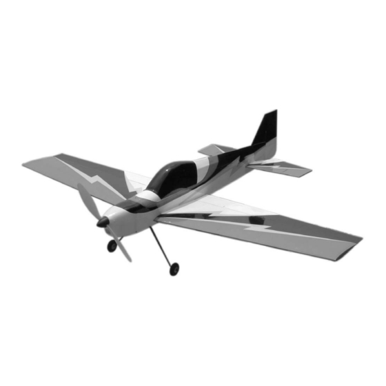
SHOCK 3D
SHOCK 3D
A radio-controlled model is not a toy and is not intended for persons under 16 years old. Keep
this kit out of the reach of younger children, as it contains parts that could be dangerous. A radio-
controlled model is capable of causing serious bodily injury and property damage. It is the buyer's
responsibility to assemble this aircraft correctly and to properly install the motor, radio, and all other
equipment. Test and fly the finished model only in the presence and with the assistance of another
experienced R/C flyer. The model must always be operated and flown using great care and common
sense, as well as in accordance with the Safety Code of the Academy of Model Aeronautics (5151
Memorial Drive, Muncie, IN 47302, 1-800-435-9262). We suggest you join the AMA and become prop-
erly insured prior to flying this model. Also, consult with the AMA or your local hobby dealer to find an
experienced instructor in your area. Per the Federal Communications Commission, you are required
to use only those radio frequencies specified "for Model Aircraft."
Carl Goldberg Products, Ltd. has inspected and certified the components of this aircraft. The company urges the buyer to perform
his own inspection, prior to assembly, and to immediately request a replacement of any parts he believes to be defective for their
intended use. The company warrants replacement of any such components, provided the buyer requests such replacement with-
in a period of 30 days from the date of purchase and provided the defective part is returned, if so requested by the company.
No other warranty, expressed or implied, is made by the company with respect to this kit. The buyer acknowledges and under-
stands that it is his responsibility to carefully assemble the finished flying model airplane and to fly it safely. The buyer hereby
assumes full responsibility for the risk and all liability for personal or property damage or injury arising out of the buyer's use of the
components of this kit.
CARL GOLDBERG PRODUCTS, LT
P.O. Box 88 Oakwood GA 30566 Phone #678-450-0085 Fax # 770-532-2163 www.carlgoldbergproducts.com
ARF
ARF
WARNING
LIMITED WARRANTY
© Copyright Carl Goldberg Products,Ltd.2004
1
Advertisement

Related Manuals for Carl Goldberg Products SHOCK 3D ARF


Summary of Contents for Carl Goldberg Products SHOCK 3D ARF
- Page 1 LIMITED WARRANTY Carl Goldberg Products, Ltd. has inspected and certified the components of this aircraft. The company urges the buyer to perform his own inspection, prior to assembly, and to immediately request a replacement of any parts he believes to be defective for their intended use.
-
Page 2: Preparing For Assembly
COVERING Before you begin assembling your Shock 3D ARF, take The Shock 3D ARF is covered in a premium polyester film some time to read through this entire instruction book. It is chosen by many of the world's top flyers for its beauty, designed to take you step-by-step through the process and toughness, and ease of application and repair. - Page 3 Caution: ITEMS NEEDED TO COMPLETE THIS AIRCRAFT RADIO GUIDANCE SYSTEM (4 CHANNEL MINIMUM REQUIRED WITH 4 SERVOS) 6” SERVO “Y” HARNESS Before starting, care- ELECTRONIC SPEED CONTROL (ELECTRIC FLY C-20 FROM GREAT fully go over all high PLANES SUGGESTED) NIMH 7C 650AAA BATTERY (2 OR 3 CELL 2100 MAH LI-PO BATTERY SUGGESTED) stress areas with an CA ACCELERATOR...
- Page 4 Hardware Parts List (Not Shown) (Shown Above) Wing 1. Fuselage (2) laser cut control horns 2. Wing with Ailerons (2) nylon swing in keepers 3. Stab with Elevators (2) 1/32 x 5-1/2” pushrods 4. Fin (1) 4-40 x 3/4” socket head bolt 5.
-
Page 5: Aileron Servo Installation
Wing The wing for the Shock 3D comes pre-assembled with the ailerons already hinged. All that is required to finish the wing is to install the aileron servos, control horns and attach the pushrods. AILERON SERVO INSTALLATION Locate the control horn slot by laying a straight edge along the outside edge on the servo opening. - Page 6 Install the control horn in the slot making sure that it is about 1/32” past the top surface of the aileron. Make sure the holes are aligned over the hinge line of the aileron. Locate the string, soft wire or a cable tie. Push it into the aileron servo cut out and fish it out the hole in the middle of the wing on the top side.
- Page 7 Screw the servo in place using the hardware supplied with the radio. Carefully pull the aileron y-connector through to the servo opening. Install the pushrod connector on your servo arm. The plastic push-on nut will retain it. Caution: Make sure the nylon nut is pushed all the way onto the pushrod connector.
- Page 8 Repeat for the other aileron servo. Stabilizer Mount Collect the following items. (1) stabilizer (1) right elevator Slide the stab into the precut slot in the fuselage. (1) left elevator (2) laser cut control horns Measure each side at the trailing edge to make (1) fuselage sure it is centered.
- Page 9 Hole for elevator wire Take one elevator half and install two CA hinges in the pre-cut slots. Locate the hole for the elevator joiner wire. Bolt the wing in place using the 4-40 x 3/4” socket head screw. Sight the stab from the rear and make sure that it is parallel with the wing.
- Page 10 Remove the pin and push elevator tight against the stab. Deflect the elevator to its full travel in the down position. Apply one drop of thin CA on each hinge. Turn the plane over and put one drop of CA on each hinge from the bottom side.
- Page 11 Glue Here Insert fin in the slot on top of fuselage and glue in place using thin CA. Install the rudder on the plane using straight pins to make sure the hinges stay centered just as we did with the elevators. Deflect the rudder in one direction to its full travel and put one drop of thin CA on each hinge.
- Page 12 Use the nylon swing in keepers to retain the pushrod on the control horns. Front Install the two servos using the hardware sup- plied with the radio. The output shafts should be to the front of the plane. Install the two pushrod connectors on the con- trol arms of the rudder and elevator servo as you did for the ailerons.
- Page 13 Landing Gear Installation Flex the landing gear legs together slightly and slide in the opening. Push all the way in. Collect the following items: (1) Landing gear (2) Wheels (2) plastic wheel retainers (1) tail skid wire (1) Landing gear cover Take the landing gear cover plate and press into the slot on top of the gear.
- Page 14 Drill a 1/32” hole in the tail skid mount 1/2” from the end. Insert the tail skid and cut a slot for the wire to fit into. Glue in place with medium CA. Motor Mount Place the top shell in place and secure using the four #2x1/2”...
- Page 15 Cowl Mounting Canopy Mounting Collect the following parts: Collect the following items: (1) Black canopy (1) Cowl (1) Hatch (1) Prop (1) Spinner (2) Plated mounting screws (2) Black mounting screws Black mounting screw The hatch is held on with a wire clip, already installed.
- Page 16 CG and Control Throws The CG should be 3-1/2” to 4” behind the leading edge at the fuselage. Our model balanced and flew with no added weight set up as shown. Notice: The plane is very responsive with a high rate of roll, so be ready for snap- use wax paper py performance.
Need help?
Do you have a question about the SHOCK 3D ARF and is the answer not in the manual?
Questions and answers