Table of Contents
Advertisement
Quick Links
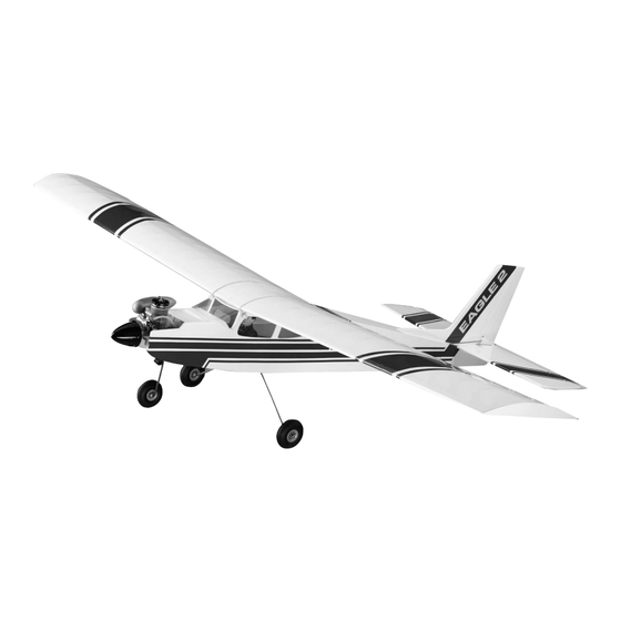
EAGLE 2
INSTRUCTIONS
Welcome to the sport of Radio Control flying!
Congratulations on selecting the Mark II Eagle--today's top trainer and all around sport model. Many new improvements
make the Mark II even easier to build and fly than past versions of the Eagle.
It may seem a bit early to speak of flying, but your successful first flight begins right here. Before starting assembly,
please read carefully through this instruction booklet. It won't take that long, and building your model and installing your
equipment will seem easier, since you will know where you are going.
WARNING
While this aircraft is an excellent first choice for novice pilots, a radio-controlled model is not a toy and is not intended for
persons under 16 years old. Keep this kit out of the reach of younger children, as it contains parts that could be danger-
ous. A radio-controlled model is capable of causing serious bodily injury and property damage. It is the buyer's respon-
sibility to build this kit correctly and to properly install the motor, radio, and all other equipment. Test and fly the finished
model only in the presence and with the assistance of another experienced R/C flyer. the model must always be operat-
ed and flown using great care and common sense, as well as in accordance with the Safety Code of the Academy of
Model Aeronautics (5151 Memorial Drive, Muncie, IN 47302), 1-800-435-9262). We suggest you join the AMA and
become properly insured prior to flying this model. Also, consult with the AMA or your local hobby dealer to find an
experienced instructor in your area. Per the Federal Communications Commission, you are required to use only those
radio frequencies specified "for Model Aircraft".
CARL GOLDBERG PRODUCTS, LTD.
©Copyright 1978
PT #2036 10/02
Advertisement
Table of Contents

Related Manuals for Carl Goldberg Products Eagle 2


Summary of Contents for Carl Goldberg Products Eagle 2
- Page 1 Also, consult with the AMA or your local hobby dealer to find an experienced instructor in your area. Per the Federal Communications Commission, you are required to use only those radio frequencies specified “for Model Aircraft”. CARL GOLDBERG PRODUCTS, LTD. ©Copyright 1978 PT #2036 10/02...
- Page 2 ITEMS NEEDED TO COMPLETE THIS KIT NECESSARY TOOLS AND SUPPLIES. RADIO GUIDANCE SYSTEMS (3 to 4-CHANNEL MISCELLANEOUS RUBBER BANDS, REQUIRED) PLUS A BOX OF #64 RUBBER BANDS .29 to .45 2-CYCLE OR .40 to .60 4-CYCLE R/C ENGINE WAXED PAPER PROPELLER, FUEL TANK &...
- Page 3 SELECTING RADIO CONTROL EQUIPMENT Your model was designed to use three or four- channel radio control equipment. In flight, the model is primarily controlled by using the ailerons and elevator (see sketch at left). One radio channel controls the ailerons. This is the primary turn control - it rolls the model.
-
Page 4: Field Equipment
ENGINE, PROPELLER & ACCESSORIES Your plane flies well using any 2-cycle engine size from .35 to .45, or 4-cycle engine .45 to .61. The numbers .35 to .45 refer to the amount of space the piston moves through inside the cylinder of the engine. - Page 5 INTRODUCTION HOW TO USE THE PLAN USING THIS INSTRUCTION MANUAL The plan is used in several ways. The wings, stabilizer, Before you start gluing and sanding, take some time and fin are assembled directly over the plan. Each wood part is becoming familiar with the plans and looking through this entire matched over its corresponding location printed on the plan and instruction booklet.
- Page 6 ADHESIVES The EAGLE II was designed for fast assembly using SUPER SUPER JET™ sets up a bit slower with plywood and hardwood, so hold such parts together a little longer than you would for balsa. Comer fil- JET™ glue, which is a specially formulated cyanoacrylate adhe- lets take even longer to dry because there is not a thin layer.
- Page 7 NOTE: In this kit version, D/C Sheets 5601, 5603, 5605, 5608 & 5609 have been replaced with D/C Sheet 5611, 5612 & 5613 (shown below) WOOD PARTS ABOUT THE WOOD IN THE KIT We strive to supply good quality materials in your kit. Wood parts Be careful when removing parts (such as fuselage sides) from are inspected with regard to the function they will serve.
-
Page 8: Tail Assembly
TAIL ASSEMBLY Make stab leading edge (LE.) from 1/4" x 1/2" balsa sticks. Cut balsa carefully to match with plan at center joint. Pin in position and glue to L.E. Joiner. Make stab T.E. from 1/4" x 1/2" balsa. Cut to match length shown on plan and glue to T.E. - Page 9 Place elevator on top of T.E. and transfer hinge locations to elevator. Position balsa elevator against stab T.E. Assemble the fin in the same manner as and mark elevator ends for match with stab. Let dry. stab tips. Cut elevator at marks to match stabilizer Mark hinge locations on fin and rudder.
- Page 10 Use your CG Hinge Marker to mark the center of the wood surfaces to be joined. Carefully cut a slot approximately 1/2” deep and slightly wider than the hinge, using your favorite knife blade. After all slots have been made, mark the center of your hinge and insert a pin (see illus.) This will hold the hinge...
- Page 11 ASSEMBLING DIE-CUT BEVELING TOOLS (FROM 1/8” PLY) Wide Strip Narrow Strip 14a. First glue narrow strip to handle, keeping them square, as shown. Then glue wide strip to handle and narrow strip, again keeping things square. Tape T.E. of elevator and rudder to work surface.
-
Page 12: Wing Assembly
WING ASSEMBLY IMPORTANT! READ THIS BEFORE STARTING ASSEMBLY YOUR EAGLE'S WING CAN BE BUILT TWO WAYS Select The Wing That Fits Your Radio and Flying Requirements. "A" or "B" WING "C" WING For 4-CHANNEL FLYING For 3-CHANNEL FLYING "A" WING — Aileron Wing for Sport & Training High Dihedral Wing for Control Without "B"... - Page 13 SINCE THE WING IS BUILT IN TWO HALVES, AND STEPS 2 TO 14 ARE REPEATED IN THE PROCESS, TWO CHECK Do not glue rib no. 2 BOXES ARE PROVIDED WITH EACH OF THESE STEPS, at this time. ONE FOR THE RIGHT WING HALF AND ONE FOR THE LEFT HALF.
- Page 14 Flush Hold parts down flat when Flush gluing Glue L.E. sheeting to L.E. and spar. Glue two rear sheeting halves together, and to spar and T.E. Pin end of L.E. and spar in place as shown . Remove rib No. 2 and scrap shims. Slide front bottom sheet forward until it just touches the L.E, and align it with end of L.E.
- Page 15 A doubled rib is necessary at the wing tip so that when you cover the wing, the tip rib won't bend. Glue two No. 4 ribs together: apply SUPER JET to one rib, stand them next to each other to check alignment, then press together.
- Page 16 With left wing still pinned down, position RIGHT WING in place next to it. Raise RIGHT WING tip and support it at 4th rib in from tip using dihedral gauges. NOTE: gauge ends are stamped, "A," "B" and "C." For "A" wing, gauge end "A" must be up. For "B"...
- Page 17 Position “T2” stamp near spar. Remove all clamps, etc. Apply two ribbons of SUPER JET to one side of both joiners, near the top and bottom, Position one end of Try top sheeting in place, trimming to fit as required. joiner in place and swing the other end up against spars Match edge of sheeting with center of rib No.
- Page 18 Cut 1-1/4" off wing tip end of ailerons, and glue to T.E. flush with end of T.E. as shown above. 23a. Place wing over plan and mark T.E. for nylon aileron bearing locations. Using a razor knife, cut slot through T.E.
- Page 19 So ailerons don’t fit tight after everything gets covered, gently sand both ends of aileron. The clearance is cor- rect when you can fit each aileron in place with a piece of matchbook cover (about 1/32") at both ends. Place TE. on plan and mark hinge locations (three hinges per wing half).
- Page 20 Glue one end of 2½" wide nylon fabric to scrap wood. Let dry until the nylon is glued solidly to the balsa. Lightly sand plastic wing tips to remove burrs from pre- cut edges. TEMPORARILY fit tips in place (they are per- manently installed after wing is covered as shown on page 39).
- Page 21 Carefully position servo 1/2" behind bottom spar and mark size for opening. Repeat gluing procedure and apply nylon around L.E., across top of wing, around T.E. and finally overlapping where you started on wing bottom. After entire center joint has been wrapped with nylon, apply another coat of glue and force it down through the nylon.
-
Page 22: Fuselage Assembly
FUSELAGE ASSEMBLY Carefully remove all fuselage (fuse) parts from die-cut plywood sheets. Lightly sand any rough edges. From 1/8"x1/2"x18" balsa, cut and glue strips to match formers as shown. Apply strips as shown. Note: Former "C" strip at bottom only. With side stamped "A"... - Page 23 To prevent oil penetration, seal area around four holes as follows. Apply a bead of SUPER JET and smear it into the wood with your finger wrapped in plastic bag. Nose Doubler Flush Align Holes Engine Bearer SMALL TRIANGLE SHAPED PIECES SHOWN ABOVE HAVE BEEN ELIMiNATED FROM THE KIT, THEY ARE NOT NEEDED Install nylon nosegear bearing on firewall Glue nose doublets to body sides, making sure to...
- Page 24 Keep edges aligned as you close plates and tape flanges together. Squeeze plates together using clamps. When dry, remove tapes and clamps. Set aside. insert top sheet under rubber band at former C, and work it towards tail, slipping it under bands as you go.
- Page 25 Place fuse over TOP VIEW on plan sheet. Viewing from above, carefully align the fuse to match plan outline. If an area of the fuse is off, adjust that portion in the direction required. Glue windshield top former and dashboard solidly in place.
- Page 26 Remove hatch cover from fuse. Refer to plan for correct placement of ply tongue, then glue tongue to hatch cover. Try in place. Glue dashboard top to hatch supports and dashboard. Tape hatch supports to both sides. Place the landing gear (L.G.) mount on inside bottom of fuse.
- Page 27 ENGINE INSTALLATION AND FUSE COMPLETION For clarity, the engine installation is shown in many small steps rather than a few general ones, It is not difficult — just thor- oughly explained. NOTE: 4-Cycle engine installations are shown on next page. Mount propeller and spinner (if used) on your engine.
- Page 29 Mark straight down through engine mounting holes onto breakaway plate. Remove engine and breakaway plate from fuse. Drill four 1/8" holes through breakaway at engine mounting hole locations (place scrap ply under parts when drilling to avoid splintering.) Permanently install four blindnuts in bottom of break away using socket head screws (and washers) to pull blindnuts up into the screw holes as shown .
- Page 30 Tape breakaway plate in position. At one of the locations marked in step 6a, drill a 1/8" hole straight down through it and engine bearer. Insert a #4-40 x 3/4" soc. head screw through hole. Continue this procedure, one hole and screw at a time, until all four screws are in place.
- Page 31 Temporarily install wing hold-down dowels in fuse. Rubber band wing in place on fuse, making sure it is centered. Viewing model from rear, see if stab sets level with respect to wing. Sand stab platform area as may be necessary to pro- vide a good level fit for stab.
- Page 32 13a. From the threaded end of two 10" rods, measure and cut one of the rods to 7" and the other rod to 4½". 13b. At cut end of rods, bend down about 1/4" making a square hook. 13c. Using the threaded end of a rod, file a slight recess 1" long at one end of each 5/16"...
- Page 33 CONSTRUCTION OPTIONS BOLT-ON WING OPTION Materials not included; Two 1/4"x 20 nylon wing bolts (CG #585) 1/4" dia x 3" wood dowel Two 1/2" x 5/8" x 2" hardwood blocks (fuselage mounting) Two 5/8" x1"x 1-5/8" balsa blocks (wing filler block) One 1/4x20 tap Klett Safety Driver (CG#610) NOTE: A Bolt-On wing looks neat and clean, but is more likely to be...
- Page 34 FUSELAGE PROCEDURE Position and glue two hardwood mounting blocks securely inside the fuselage as shown using Epoxy or Super Jet. Glue them well, these glue joints must be strong. Drill a 1/4" diameter hole through former "B". Locate hole by holding drill up against bottom edge of cabin top doubler and then drill through former at a slight angle so hole matches downwards slant of dowel.
- Page 35 ELECTRIC POWER OPTION ELECTRIC flying is clean and quiet. There is no messy engine exhaust ASTRO GEARED 25 COBALT MOTOR oil so your model stays clean. The items below are available from Astro Flight Inc. Materials not included: Cobalt 25 Electric Motor (Geared) Electronic Speed Control Three 1200 MAH batteries Three Battery Switch Harness...
- Page 36 As the motor uses battery power the batteries will become warm. Cooling air enters through the firewall openings and exits the fuse tail end. In flight, this air movement will help cool the batteries.
-
Page 37: Optional Float Installation
OPTIONAL FLOAT INSTALLATION FLOATS make any large pond or lake your runway. Water flying adds a new dimension to your flying fun. CG Super Floats are recommended because they are easy to build and perform well. Floats can be added at a later time with little modification to your model. - Page 38 GENERAL. Any irregularities in the wood surface will show on the covering, so a good covering job should be preceded by careful sanding, filling of nicks and dents [we recommend CGM Model Mate™ balsa filler), and then more sanding. For this final sanding, use fine sandpaper (240-320 grade) and a sanding block.
- Page 39 For best results, a darker color should go over a lighter one. Smaller designs should be positioned and tacked in place at one end. Then, work the iron down the rest of the design, smoothing out the design as you go. Larger designs (such as sunbursts) should be positioned and the widest end tacked down first.
- Page 40 COVERING THE FUSELAGE COVERING THE TAIL Following the same procedure as with the wing, cover the For added realism, the cabin interior may be painted now. stabilizer/elevator and the fin/rudder. After covering over Use any of the paint materials recommended on the inside the hinge holes, immediately go back and slit the cover- front cover of this book;...
- Page 41 WINDSHIELD CAUTION: FOLLOW INSTRUCTIONS CAREFULLY FLASHING 1) CAREFULLY REMOVE FLASHING AT BOTTOM OF WINDSHIELD SIDES. 2) TRIM SCRAP FROM FRONT OF WINDSHIELD BY CUTTING ON MARKED LINE. Apply covering first to the bottom and then to the sides of the fuse. Cover the top of the fuse last. 3) MAKE TWO VERTICAL CUTS AT MARKED LINES.
-
Page 42: Final Assembly
SIDE WINDOWS Glue windshield in place, taking care to keep glue only on the edge of the plastic. After the SUPER JET has dried, a trace of white film may appear inside the wind- WINDOW GLUING shield. Wipe off with a damp cloth. FLANGE (SHOWN SHADED) Optional: Improve the appearance and strength by... -
Page 43: Fuel System
Insert formed wire maingear struts in fuse. Position nylon landing gear straps; then mark, drill, and mount with #2 x 5/16" screws (see sketches above and illustra- tion on page 10). Press one of the four steel collars into the pocket in the nylon steering arm (side holes must be aligned). - Page 44 TREAT YOUR RADIO RIGHT - AND IT WILL DO THE SAME FOR YOU! by Hal deBolt Famous R/C Pioneer Today's RC systems are very well engineered and constructed. However, they will remain only as good as the way in which they are USED.
- Page 45 RADIO PREPARATION & INSTALLATION 1. Before continuing, make sure each of the following items Set RC airborne equipment temporarily in fuse (refer to plan for approximate location). has been completed: a) Battery most forward. Model is fully covered and painted wherever necessary. b) Receiver (Rx) next.
- Page 46 3. Radio Installation. Read and follow the instructions that came with your radio. If your batteries are dry cells, they should be fresh. If rechargeable nicads, they should be fully charged, C. Hook-up Radio and Try Operation. YOUR TRANSMITTER (Tx) IS BUILT LIKE ONE OF THOSE Refer to "Transmitter Function Sketch"...
- Page 47 4. Servo Arrangement. With throttle servo at forward position, place servo so output wheel is on same side as engine throttle arm. Rudder servo should be on side opposite to throttle servo so it can drive the nosegear steering arm in a nearly straight line.
- Page 48 Mounting The Control Horns and Pushrods. Rudder Horn (Small): Refer to fuse side view on plan for correct location. Tack-cement small horn on correct side of rudder. Drill through holes in horn, and mount nut plate on other side using screws as shown. Trim screws flush with nut plate.
- Page 49 7. Mounting Servos Tape front end of rudder and elevator push rods up out of the way under cabin top doublers. Glue two ply braces to bottom of ply servo tray as shown. Insert the soft rubber gram mete into the mounting holes of your servos and tray.
- Page 50 Installing The Throttle Pushrod. Screw mini-snap on the extra-long remaining threaded rod. Carefully bend rod to fit curve of throttle pushrod as shown in fuse top view on plan. Cut a 10½" throttle pushrod guide tube from long nylon tube (remainder is steering pushrod guide tube).
- Page 51 10b. Hooking Up Aileron Pushrods ("A" or "B" Wing Only). Re-install aileron servo in wing. Tape ailerons in neutral position (so flat bottom of wing and ailerons are flush). Install horn brackets on aileron horns as shown. Install mini- snaps on each 7" True 1/16" threaded rod, then connect mini- snaps to horn brackets.
- Page 52 14. Setting Control Surfaces. CUT GAUGES FROM PLAN All pushrods must move freely, without binding; adjust il required for smooth operation. When selling control travel, be cautious that no servo is hooked to a control in a manner that prevents the servo wheel from moving through its complete range of rotation.
- Page 53 SETTING UP YOUR ENGINE Do not attempt to fly your model until the engine runs dependably. It should idle without stopping and the transition through alt engine speeds should be smooth. WARNING! The turning propeller can cause serious injury, such as deep cuts.
- Page 54 FIRST START ENGINE. SLOW SPEED MIXTURE ADJUSTMENT To start engine, first open 1/8 to 1/4 throttle. Prime with 4-6 Now reduce engine throttle to idle speed. If it will idle, wait for drops of fuel in carb, attach glow plug and flip prop counter- 10 seconds and hit full throttle.
- Page 55 WHERE TO FLY Fly only in areas sanctioned for R/C and known to be free of radio interference. Ask your hobby dealer or other modelers if there is an R/C flying field that is used by a local R/C club. This is the ideal place to fly.
- Page 56 Check also to see that your nose wheel turns to the right when you give right rudder. Your throttle should open to permit full power when the stick or tab is moved forward or up. Make sure that everything is neatly and firmly in place—engine fastened down, servos snugged down, receiver and battery wrapped in foam rubber, tank properly supported, etc.
-
Page 57: First Flights
FIRST FLIGHTS INTRODUCTION There is no way to fully explain the principals of flight and the tech- One of the most important yet sometimes neglected pre-flight niques of flying in only a few pages. Entire books have been written checks is to always make sure the wing is securely banded to the about apparently simple subjects as the shape of the wing. - Page 58 OVERSTRESSING THE AIRFRAME, Even world class aero- batic competition planes tan be overstressed. The Mirage is very strong but can be broken in flight by over-speeding and then jerk- ing the controls. If you find yourself In a steep high-speed dive, immediately switch motor off, level the wings and gently pull the stick back (add up elevator) to recover.
- Page 59 Tigers easily convert into a tail-dragger configuration. The Tiger 2, Tiger 2 ARF, Tiger 60 & Tiger 60 ARF. Only from Carl Goldberg Products. PO Box 818, Oakwood GA 30566 Info: 678-450-0085 Fax: 770-532-2163 www.carlgoldbergproducts.com...
Need help?
Do you have a question about the Eagle 2 and is the answer not in the manual?
Questions and answers