Table of Contents
Advertisement
Quick Links
S
U
S
U
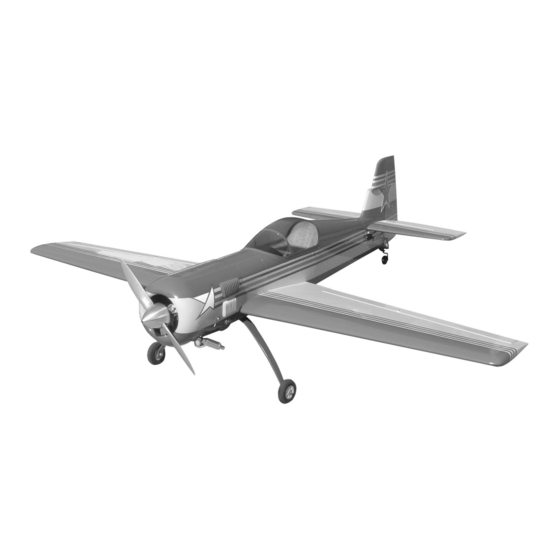
Aerobatic flying just doesn't get any better than this Sukhoi ARF. Its clean lines, long tail moment, and superb
wing design will reward you with the maneuvers you love - knife edge, split S, lumcevac, torque rolls, snaps,
and ground-hugging inverted flight. What's more, we've engineered this ARF to get you into the air with a min-
imum of fuss. So take a few minutes to carefully read the introductory material and then get to work. You'll
soon be out at the field with a classic aerobatic champion!
A radio-controlled model is not a toy and is not intended for persons under 16 years old. Keep
this kit out of the reach of younger children, as it contains parts that could be dangerous. A radio-
controlled model is capable of causing serious bodily injury and property damage. It is the buyer's
responsibility to assemble this aircraft correctly and to properly install the motor, radio, and all other
equipment. Test and fly the finished model only in the presence and with the assistance of another
experienced R/C flyer. The model must always be operated and flown using great care and common
sense, as well as in accordance with the Safety Code of the Academy of Model Aeronautics (5151
Memorial Drive, Muncie, IN 47302, 1-800-435-9262). We suggest you join the AMA and become prop-
erly insured prior to flying this model. Also, consult with the AMA or your local hobby dealer to find an
experienced instructor in your area. Per the Federal Communications Commission, you are required
to use only those radio frequencies specified "for Model Aircraft."
Carl Goldberg Products, Ltd. has inspected and certified the components of this aircraft. The company urges the buyer to perform
his own inspection, prior to assembly, and to immediately request a replacement of any parts he believes to be defective for their
intended use. The company warrants replacement of any such components, provided the buyer requests such replacement with-
in a period of 90 days from the date of purchase and provided the defective part is returned, if so requested by the company.
No other warranty, expressed or implied, is made by the company with respect to this kit. The buyer acknowledges and under-
stands that it is his responsibility to carefully assemble the finished flying model airplane and to fly it safely. The buyer hereby
assumes full responsibility for the risk and all liability for personal or property damage or injury arising out of the buyer's use of the
components of this kit.
CARL GOLDBERG PRODUCTS, LTD.
P.O. Box 88 Oakwood GA 30566 Phone #678-450-0085 Fax # 770-53-63 www.carlgoldbergproducts.com
K
H
O
K
H
O
I
A
I
A
WARNING
LIMITED WARRANTY
R
F
R
F
Advertisement
Table of Contents

Related Manuals for Carl Goldberg Products Sukhoi ARF


Summary of Contents for Carl Goldberg Products Sukhoi ARF
- Page 1 Aerobatic flying just doesn't get any better than this Sukhoi ARF. Its clean lines, long tail moment, and superb wing design will reward you with the maneuvers you love - knife edge, split S, lumcevac, torque rolls, snaps, and ground-hugging inverted flight. What's more, we've engineered this ARF to get you into the air with a min- imum of fuss.
- Page 2 INTRODUCTION COVERING USING THIS INSTRUCTION MANUAL The SUKHOI ARF is covered in a premium polyester film Before you begin assembling your SUKHOI ARF, take chosen by many of the world's top flyers for its beauty, some time to read through this entire instruction book. It toughness, and ease of application and repair.
- Page 3 OPTIONAL: SOFT PENCIL 1/5 PILOT FIGURE A FEW STRAIGHT OR "T" PINS ADJUSTABLE WRENCH WIRE CUTTER (DYKES) NOTE: The SUKHOI ARF covering matches Cub OPTIONAL HEAT GUN/COVERING IRON Yellow(#884), Deep Blue(#873) and True ACID BRUSH Red (#877) Oracover. ELECTRICAL TAPE PIECE OF MEDIUM SANDPAPER 5 FT.
-
Page 4: Wing Assembly
WING ASSEMBLY Select the aileron for the wing on which you AILERON INSTALLATION are working and insert the exposed half of each hinge into the aileron slots. Slide the aileron toward the wing until no gap remains between the aileron and the wing. -
Page 5: Aileron Servo Installation
AILERON SERVO INSTALLATION Note: The following pictures may not exactly match the hardware you are using. Always check the radio manufacturer's instructions when installing radio equipment. When the epoxy is dry, drill 1/16" holes into the servo blocks and, using the screws sup- plied with the radio, mount the servo onto the blocks. -
Page 6: Aileron Control Horn Installation
Using the #4 x 1/2" screw supplied with this kit, screw the door to the mounting plate. Position the control horn bolt so that it is 3/4” back from the hinge line on the mark that you Repeat the above steps for the second aileron jut made. -
Page 7: Tail Construction
TAIL CONSTRUCTION STAB INSTALLATION Collect the following items (2) Right & left Stab (1) Small stabilizer tube Second way (Suggested) Draw a outline where both stabilizers meets the fuselage side. Slide the small stabilizer tube into one side of the stab. Then slide the assembly into the hole in the fuselage till the stab is flush against the fuse. -
Page 8: Rudder And Elevator Installation
RUDDER AND ELEVATOR INSTALLATION HINGING THE ELEVATORS Collect the following items: (2) Elevators (6) Hinges Align the rear of the fin with the rear of the fuselage. Make sure that the fin is perpendicular to the stab and fit flat on the fin platform. Make a mixture of epoxy and epoxy the fin onto the fin platform Again, make sure the the Take three hinges and, as with the aileron... -
Page 9: Installing The Elevator Servos
INSTALLING THE ELEVATOR SERVOS Collect the following items: (2) servos and mounting hardware (6) 24” servo extensions (2) 4-40 x 3-1/2” double threaded rod (4) 4-40 Hex Nut (4) 4-40 Golden Clevis (2) 6-32 x 2” Flat Head Screws (2) 6-32 Hex Nut (2) #6 Flat Washer With the servo in place, make a mark at a 90º... - Page 10 RUDDER AND RUDDER CABLES Collect the following items: (1) 6-32 x 3” All threaded rod (1) Black Adjustable Horn Bracket (1) Small White Adjustable Horn (2) 6-32 Hex Nut (2) #6 Flat Washer (1) Rudder (4) Hinges (1) Cable (2) Brass Tubes 1/16 OD x 1/4” (2) 2-56 Threaded Rods with holes Insert the 6-32 x 2”...
- Page 11 Thread the white adjustable horn on the rod first. Insert the horn bracket far enough so that the black horn will fit on the rod completely. Thread the 2-56 end of the cable into the tub- Do this for both sides of the rudder. ing and pull the tubing out the rear cable exit.
-
Page 12: Installing The Landing Gear
Repeat steps 2 & 3. Note: The springs should be tight enough so that when you move the tailwheel it will move the rudder. Thread the 6-32 x 3” rod into brass nob that is on top of the axle on the tailwheel bracket. Install the tailwheel using the 1/8”... -
Page 13: Installing The Rudder Servo
INSTALLING THE RUDDER SERVO Collect the following items: (2) Servo with mounting hardware (2) Brass Tubes 1/16 OD x 1/4” (2) 2-56 Threaded Rods with holes (2) 2-56 Golden Clevis (2) 2-25 Hex Nut Assemble the 2-56 cable end same as shown above. - Page 14 Keeping the engine perpendicular to the table top, clamp the other motor mount to the engine. Mark and drill the second motor mount then screw the mount to the engine. Measure across the top of the motor mount and find the center. Place a mark at that point. Extend the lines on the firewall as shown above.
-
Page 15: Fuel Tank Assembly
FUEL TANK ASSEMBLY Gather the following items (1) fuel tank (1) rubber tank stopper (1) clunk PUSHROD CONNECTOR (1) 3mm x 25mm screw (1) cap washer large (1) cap washer small (2) 3mm x 40mm brass tube SNAP NUT (1) 3mm x 60mm brass tube Mount throttle servo in tray on the marks (1) silicone tube 4mm x 80mm you made earlier... -
Page 16: Installing Fuel Tank
INSTALLING FUEL TANK Gather the following items (1) Velcro Hook & Loop (1) Foam Rubber (Not Included) Install the 4mm silicone tube to the short brass tube and install the clunk to the other end of the silicone tube. This is the fuel pick- up and must be free to “flop”... -
Page 17: Mounting The Cowl
Unscrew the engine from the motor mounts. Place the cowl on the fuselage and fasten Insert foam on both sides of the fuel tank. using the 4-40 x 1/2” bolts and washers. Note: This is also a good place for the radio battery if Re-tape the clear plastic sheet on the marks needed. - Page 18 HATCH AND CANOPY BOLTING ON THE WING Gather the following items Gather the following items (1) Right & Left Wing Panels (1) Hatch (2) 1/4-20 x 2” Nylon Bolt (4) 4-40 x 1/2 Socket Head Bolt (1) Wing Tube (4) #4 Washer (1) Cockpit insert (1) Canopy Fit the hatch under the cowl (tight fit) and slide...
- Page 19 BALANCING AND CONTROL THROWS CG Balancing Throws Balancing the Sukhoi is very important, We have provided two sets of throws. you might need to use weight depending Use the lower throws on the first flights on the servos and engine that you use. then work your way up to the higher Start out with the balance point at 5”.
Need help?
Do you have a question about the Sukhoi ARF and is the answer not in the manual?
Questions and answers