Advertisement
Quick Links
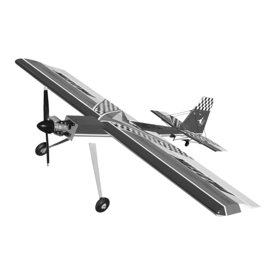
Wild Stick 120
Wild Stick 120
C C A
A R R L L G G O
O L L D
D B B E E R R G G P P R R O
O D
D U U C C T T S S L L T T D
D . .
C C A
A R R
P.O. Box 818, Oakwood, GA 30566 • 678-450-0085 • Fax: 770-532-2163 • www.carlgoldbergproducts.com
P.O.
©copyright 2004 Carl Goldberg Products.
Advertisement

Related Manuals for Carl Goldberg Products WILD STICK 120


Summary of Contents for Carl Goldberg Products WILD STICK 120
- Page 1 D U U C C T T S S L L T T D D . . C C A A R R P.O. Box 818, Oakwood, GA 30566 • 678-450-0085 • Fax: 770-532-2163 • www.carlgoldbergproducts.com P.O. ©copyright 2004 Carl Goldberg Products.
- Page 2 47302 LIMITED WARRANTY Carl Goldberg Products is proud of the care and attention that goes into the manufacture of parts for its model kits. The company warrants that for a period of 90 days, it will replace, at the buyers request, any part or materi- al shown to the company's satisfaction to have been defective in workman- ship or material at the time of purchase.
- Page 3 Wild Stick Wild Stick Congratulations on your purchase of the Lanier Wild Stick 120. This is a very unique aircraft, with great 3-D capabilities. Every effort has been made to produce a lightweight, straight, easy to assemble aircraft. Because of its oversize control surfaces which are double beveled to allow for extreme throws, great care must be taken in the set-up and flying of this airplane.
- Page 4 Wild Stick 120 Parts Layout Colors Fuselage True red #866 wing panels White #870 ailerons Black #874 Flaps Blue Deep Blue #873 Stabilizer yellow Bright Yellow #872 Elevators Rudder landing Gear...
- Page 5 Wild Stick 120 Hardware List Wing bolts Landing Gear 4mmx40mm 4mmx12mm bolts 4mm flat washers 4mm washers 4mm wheel collars Fuel tank with hardware 1 4mm axels 4mm lock nuts Tail wheel 3.5” wheels Tail wheel bracket metal rudder horn...
-
Page 6: Building Instructions
Wild Stick 120 BUILDING Wing Construction INSTRUCTIONS Collect the following parts: 1. left and right wing panel Before starting to build this kit, we 2. dihedral brace urge you to read through these 3. wing holddown bolts(2) instructions. They contain some... - Page 7 Wild Stick 120 Tail construction 3. Spread epoxy on the root rib of each wing panel. Use a thin scrap of wood and work some of the epoxy locate the following parts; down into the slots for the dihedral 1. stabilizer with elevators brace on each panel.
- Page 8 Wild Stick 120 4. Set the stab in place in the slot on the rear of the fuselage. Align holes over hinge line 2. Remove the elevators from the stab and make sure all the hinges are centered in the slots. To make sure...
- Page 9 Wild Stick 120 remove covering 9. Remove the covering from the bot- 7. use a razor blade or e-xacto knife tom portion of the rudder where it to carefully remove the covering plugs into the stab. inside the marks on the bottom of the stab.
- Page 10 Wild Stick 120 11. Epoxy the fin in place making sure it is square to the stab and centered on the fuselage in the rear. 1.Take four of the angle brackets, two screws, two nuts and four flat wash- Flying Wires ers and bolt to the top of the fin in the predrilled holes.
- Page 11 Wild Stick 120 3.Mount the aluminum bracket on the Use the tail wheel bracket to align bottom of the fuselage using the two the flying wire bracket at the front 2mmx10mm screws. edge of the mounting block. Align the tail wheel bracket at the rear edge of the fuselage and mount the alu- minum bracket at the front edge.
- Page 12 Wild Stick 120 4.Take one of the 7” pushrods and make sure the clevis is screwed on with about 1/16” of threads showing on the inside. Install the clevis on the angle bracket and mark the location over the hole on the fuselage brack- et.
- Page 13 Wild Stick 120 landing Gear 2. install the axels using the aircraft lock nuts. locate the following parts: 1. landing gear 2. Two wheels 3. Two axels 4. two axel nuts 5. Four wheel collars 6. Six flat washers 7. Four mm screws 1.
- Page 14 Wild Stick 120 Tail wheel 2. Center the tiller arm in the collar and tighten the set screw. Screw the Locate the following Parts: nylon horn brackets on each end. Tail wheel bracket Install the tail wheel using the 3mm collar to retain.
- Page 15 Wild Stick 120 Engine Installation locate the following parts: 1. Two motor mounts 2. Four 4mmx20mm screws 3. Four 4mm blind nuts 4. Four 4mmx25mm bolts 5. Four 4mm aircraft lock nuts. 6. 8 4mm flat washers 1. Clamp your engine to the two motor mount making sure that both 4.
- Page 16 Wild Stick 120 5. pull the nuts up with the wire then install the bolt and washer through the hole and tighten to finish pulling the blind nut into the hole. 6.After all four nut are pulled tight, install the engine using the four 4mm bolts and washers.
- Page 17 Wild Stick 120 2. install the servos using the hard- 4. Use a straight edge to mark the ware supplied with the radio. Use the location of the four aileron horns in stings installed in the wing to pull line with the output arm. install the...
- Page 18 Wild Stick 120 5. Locate one of the 3mm pushrods, metal clevis, two 3mm nuts and sili- cone clevis keeper. Make sure the clevis is screwed on the pushrod with about 1/16” of threads showing on the inside of the clevis. Install the clevis on the control horn and the servo arm.
- Page 19 Wild Stick 120 swage rigging coupler 9. Locate the pull-pull cable, cable ends and cable swages. Take two of the rigging couplers and two of the swages and insert the cable through the swage, through the rigging cou- pler and loop back through the swage.
- Page 20 Wild Stick 120 Throttle servo 1. Use a long drill for the throttle 2. On Four stroke engines you need to pushrod hole and align with throttle bend a z-bend in the pushrod and arm. attach to the throttle arm.
- Page 21 Wild Stick 120 5. Slide the 5mm plastic tube on the throttle pushrod until it extends 1/4” through the firewall. Install the pushrod connector on the servo. Open the throttle full and set the throttle servo to full. Tighten the set screw on the pushrod connector onto the pushrod.
- Page 22 Wild Stick 120 Fuel Tank 3. Attach the pushrod to the control horn on the elevator and the output arm on the servo. Center the servo and the elevator and adjust length. 1. Locate the fuel tank and hard- When correct tighten the jam nut ware.
- Page 23 Wild Stick 120 Final Setup The CG should be between 5.75” and 6.5” behind the leading edge of the wing. The control throws should be : Elevator Low Rate +or- 1” High Rate All you can get Ailerons Low Rate +or- 1/2”...
- Page 24 If the flight modes are not set-up correctly, the plane could be unflyable in that con- figuration, so be ready to turn it off if you cannot handle it. Thank you buying the Wild Stick 120 so go have some fun.
Need help?
Do you have a question about the WILD STICK 120 and is the answer not in the manual?
Questions and answers