Advertisement
Quick Links
Wild Stick .40
Wild Stick .40
C C A
A R R L L G G O
O L L D
D B B E E R R G G P P R R O
O D
D U U C C T T S S L L T T D
D . .
P.O. Box 818, Oakwood, GA 30566 • 678-450-0085 • Fax: 770-532-2163 • www.carlgoldbergproducts.com
©copyright 2004 Carl Goldberg Products.
Advertisement

Related Manuals for Carl Goldberg Products Wild Stick .40


Summary of Contents for Carl Goldberg Products Wild Stick .40
- Page 1 D B B E E R R G G P P R R O D U U C C T T S S L L T T D D . . P.O. Box 818, Oakwood, GA 30566 • 678-450-0085 • Fax: 770-532-2163 • www.carlgoldbergproducts.com ©copyright 2004 Carl Goldberg Products.
- Page 2 47302 LIMITED WARRANTY Carl Goldberg Products is proud of the care and attention that goes into the manufacture of parts for its model kits. The company warrants that for a period of 90 days, it will replace, at the buyers request, any part or materi- al shown to the company's satisfaction to have been defective in workman- ship or material at the time of purchase.
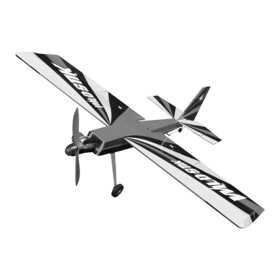
- Page 3 Wild Stick .40 Wild Stick .40 Congratulations on your purchase of the Lanier Wild Stick .40. This is a very unique aircraft, with great 3-D capabilities. Every effort has been made to produce a lightweight, straight, easy to assemble aircraft. Because of its oversize control surfaces which are double beveled to allow for extreme throws, great care must be taken in the set-up and flying of this airplane.
- Page 4 Wild Stick .40 Parts Layout (1) Fuselage (2) Wing Halves (3) Ailerons (4) Stabilizer (5) Elevator Halves 2 (6) Fin (7) Rudder (8) Landing Gear (9) Dihedral Brace...
- Page 5 Wild Stick .40 Pushrods tail wheel bracket 2mmx12” pushrods with clevis 2mm wheel collar for tail wheel Nylon swing in keepers 25mm tail wheel 2.5mmx10mm screws flat washers Landing gear 2-1/2” wheels 4mm axels 4mm aircraft lock nuts 4mm wheel collars...
- Page 6 See the list at the end of the instruc- tion book for a list of additional R/C equipment you will need to complete the Wild Stick .40. 2. Mix some 30 minute epoxy and spread on all sides of the dihedral...
- Page 7 Wild Stick .40 Tail construction 3. Spread epoxy on the root rib of each wing panel. Use a thin scrap of wood and work some of the epoxy locate the following parts; down into the slots for the dihedral 1. stabilizer with elevators brace on each panel.
- Page 8 Wild Stick .40 4. Set the stab in place in the slot on the rear of the fuselage. Align holes over hinge line 2. Remove the elevators from the stab and make sure all the hinges are centered in the slots. To make sure...
- Page 9 Wild Stick .40 remove covering 9. Remove the covering from the bot- 7. use a razor blade or e-xacto knife tom portion of the rudder where it to carefully remove the covering plugs into the stab. inside the marks on the bottom of the stab.
- Page 10 Wild Stick .40 1. place the tail wheel bracket on the bottom of the fuselage with the tiller are flush against the rear of the fuselage and centered. 2. Drill a 1/16” hole at the three holes in the tail wheel bracket.
- Page 11 Wild Stick .40 5. Fit the landing gear to the bottom of the fuselage and install the four screws and flat washers. Use lock- 7. install the wheels using one wheel tite on the screws. collar on the inside and one on the outside of the wheel.
- Page 12 Wild Stick .40 Engine Installation locate the following parts: 1. Two motor mounts 2. Four 4mmx25mm screws 3. Four 4mm blind nuts 4. Four 4mmx35mm bolts 5. Four 4mm aircraft lock nuts. 6. 8 4mm flat washers tail wheel tiller arm into rudder 2.
- Page 13 Wild Stick .40 5. pull the nuts up with the wire then install the bolt and washer through the hole and tighten to finish pulling the blind nut into the hole. 6.After all four nut are pulled tight, install the engine using the four 4mm bolts and washers.
- Page 14 Wild Stick .40 2. install the servos using the hard- 4. Use a straight edge to mark the ware supplied with the radio. Use the location of the four aileron horns in stings installed in the wing to pull line with the output arm. install the...
- Page 15 Wild Stick .40 5. Locate one of the 2mm pushrods, metal clevis, silicone clevis keeper, and nylon swing in keeper. Make sure the clevis is screwed on the pushrod with about 1/16” of threads showing on the inside of the clevis. Install the clevis on the control horn.
- Page 16 Wild Stick .40 8. Install the elevator servo, throt- tle servo and switch in the cutouts provided in the servo tray. 10. Bend a 90 degree angle in the end of the throttle pushrod and cut at 3/8”. Attach to the throttle arm and retain with a nylon swing in keeper.
- Page 17 Wild Stick .40 13. Locate the 14” wooden dowel, two 12” threaded rods with clevis, one 6” piece of 2mm wire, and two pieces of Shrink tubing. 14. Take the two pushrods and bend a 90 degree angle at 8-1/2” on one and 8-11/16”...
- Page 18 Wild Stick .40 Fuel Tank 18. Install the 6” piece of wire on the other end of the dowel and glue in place. Install the heat shrink tube. 19. Install the pushrod in the fuse- lage guiding the rods out each side of the fuselage in the slots provided.
- Page 19 Wild Stick .40 Final Setup The CG should be between 4” and 4- 1/2” behind the leading edge of the wing. The control throws should be : Elevator Low Rate +or- 1” High Rate All you can get Ailerons Low Rate +or- 1/2”...
- Page 20 If the flight modes are not set-up correctly, the plane could be unflyable in that con- figuration, so be ready to turn it off if you cannot handle it. Thank you buying the Wild Stick .40 so go have some fun.
Need help?
Do you have a question about the Wild Stick .40 and is the answer not in the manual?
Questions and answers