Table of Contents
Advertisement
Quick Links
Download this manual
See also:
Instruction Manual
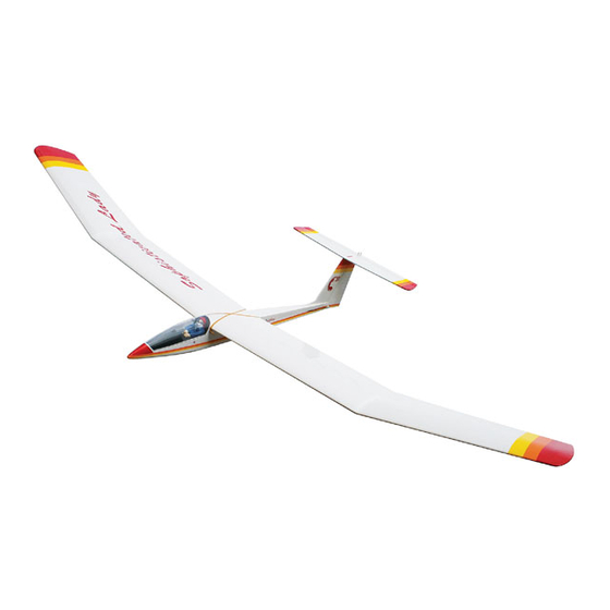
Sophisticated Lady
INSTRUCTIONS
he SOPHISTICATED LADY is a sailplane design that blends simple straight-forward construction with
T
the elegant styling of a sleek, full-scale soaring machine. The clean lines have not compromised the
functionality of this model aircraft, which you will find a delight to fly both in thermals and on the slope
And if it's competition you desire, this "Lady" can compete with the best and look great in the winners'
circle!
Although a simple two-channel radio meets the minimum requirements for piloting this model, a third
channel is more desirable, enabling you to control airborne "power-on/power-off" commands when the
electric power pod is installed. The Carl Goldberg Products Electric Power Pod (Item #678) is an option-
al accessory which provides power assistance for small-field launching, or when the towline is just too
much trouble. A small gas engine is also a power option. In addition, your sailplane so may be
launched via high start, hand tow, or winch, and, if you live in a hilly or mountainous area, you may wish
to simply pitch your glider off the slope. Whichever method you choose, the SOPHISTICATED LADY
will provide many hours of enjoyment.
WARNING!
THIS IS NOT A TOY! A radio-controlled model is not a toy and is not intended for persons under 16 years old. Keep this
kit out of the reach of younger children, as it contains parts that could be dangerous. A radio-controlled model is capable
of causing serious bodily injury and property damage. It is the buyer's responsibility to build this kit correctly and to prop-
erly install the motor, radio, and all other equipment. Test and fly the finished model only in the presence and with the assis-
tance of another experienced R/C flyer. The model must always be operated and flown using great care and common
sense, as well as in accordance with the safety standards of the Academy of Model Aeronautics (5151 Memorial Drive,
Muncie, IN 47302, 1-800-435-9262). We suggest you join the AMA and become properly insured prior to flying this model.
Also, consult with the AMA or your local hobby dealer to find an experienced instructor in your area. Per the Federal
Communications Commission, you are required to use only those radio frequencies specified "for Model Aircraft."
Carl Goldberg Products, Ltd.
P.O. Box 818
4462 Oakwood Road Oakwood, GA 30566 Phone # 678-450-0085
Fax # 770-532-2163
E-mail: Questions@carlgoldbergproducts.com
©Copyright 1986
Pt. # 2083 1/02
Advertisement
Table of Contents

Related Manuals for Carl Goldberg Products Sophisticated Lady


Summary of Contents for Carl Goldberg Products Sophisticated Lady
- Page 1 "power-on/power-off" commands when the electric power pod is installed. The Carl Goldberg Products Electric Power Pod (Item #678) is an option- al accessory which provides power assistance for small-field launching, or when the towline is just too much trouble.
- Page 2 LIMITED WARRANTY Carl Goldberg Products, Ltd. takes pride in the care and attention given to the manufacture of its model airplane kits. The company warrants replacement of any materials found to be defective for their intended use, prior to their use in construction of the aircraft, provided the buyer requests such replacement within a period of one year from the date of purchase and provided the defective part is returned, if so requested by the company.
- Page 3 Building options, as well as balancing, set- up, and flying the model are covered. IDENTIFYING PARTS Like a full-size airplane, the SOPHISTICATED LADY is Parts for the wing are bundled together; likewise, parts built from basic structures (stabilizer, fin, wing, etc.), which for the tail assembly are also grouped.
- Page 4 WOOD PARTS ABOUT THE WOOD IN THE KIT Be careful when removing parts (such as fuselage We strive to supply good quality materials in your kit. sides) from the die-cut sheets. Long parts are fragile Wood parts are inspected with regard to the function until Super Jeted into a structural unit.
- Page 5 AIRPLANE STRUCTURE MAIN & REAR SPAR RIBS ELEVATOR HORIZONTAL STABILIZER OUTBOARD PANEL TAIL ASSEMBLY HINGES CENTER SHEETING INBOARD PANEL RUDDER WING ASSEMBLY CANOPY COCKPIT DETAIL COCKPIT PLATFORM TRAILING EDGE FUSELAGE TOW HOOK LEADING EDGE CHIN BLOCK LEADING EDGE SHEETING NOSE BLOCK END VIEW OF STRIP WOOD PARTS BASSWOOD BALSA...
-
Page 6: Tail Construction
TAIL CONSTRUCTION Collect the following items. (4) 3/16 x 3/8 x21” BALSA PT. #4853 (1) 1-3/4 SQ. x 21” BALSA PT. #4696 (3) 5/64 X 3/16 X 24” BALSA PT. #4698 (1) 1/2” SQ. x 8-1/4” BALSA PT. #4701 (1) CENTERLINE MARKER PT. - Page 7 Carefully remove the die cut fin parts and light- Glue the remaining parts #1 and #2 to the fin ly sand any rough edges. assembly and trim the nylon tube flush with the trailing edge of part #2. GLUE DORSAL Glue the 3/16"...
-
Page 8: Wing Construction
WING CONSTRUCTION IMPORTANT: YOU WILL BE BUILDING A RIGHT AND THEN A LEFT WING. FOLLOW THE STEPS CAREFULLY TO AVOID CONFUSION. Collect the following items: (2) D/C SHT. 4001 (5/64” Balsa) PT. #3601 Contains: WING RIBS (2) D/C SHT. 4002 (5/64” Balsa) PT. - Page 9 Following the same procedure, trim and fit two more sheeting pieces for the bottom center section. REAR SPAR JOINER HAS TAPERED ENDS. Fit the first sheeting piece between the spars and, holding it flat to the building board, Super Jet the edges to the spars. Install the other two sheeting pieces in the same manner.
- Page 10 REMOVABLE TIP OPTION NOTE: The materials needed to make the wing tip removable are NOT INCLUDED in your kit. Necessary templates for this option are found in the upper right corner of the wing half of the plan. Follow these steps ONLY IF YOU WANT TO BE Using no glue, set ribs #7, 9,12, and 15 in their ABLE TO REMOVE THE WING TIPS.
- Page 11 Referring to the TIP OPTION on the plan, care- fully groove the spars for the wire and for the brass tube. IMPORTANT: "A" AT TOP Tack-glue the WIRE to the OUTBOARD SPAR and the BRASS TUBE to the INBROARD SPAR. Plug the wing panels together and make cer- tain the wing structures butt evenly at the poly- MATCH GAUGES WITH PLAN...
- Page 12 Set the outboard L.E. sheeting in place, align- Trim off excess spar material extending beyond ing the inboard edge of the sheet with the joint the #15 ribs (wing tip ribs) between rib #6 and the #6a doubler. When correctly positioned, tape the sheeting to the Glue trip strip to the #15 ribs, as shown.
- Page 13 Trim to fit between the spars, just as was done in Step 7. When satisfied with the fit, glue in place. Glue the L.E., the bottom sheets, and the T.E. together at the center joint. GLUE ALL JOINTS BEFORE COMPLETE- ING SHEETING Examine the center joint for good fit and align- ment of the L.E., the spars, the joiners, and the...
- Page 14 ALUMINUM Before continueing, protect fingers with a plas- SHEET tic bag or plastic wrap. Using 240 grit (fine) sandpaper, flat sand the Starting with the bottom of the wing, apply a entire wing to blend the surfaces and remove squiggle of glue along the wing joint and lay the high spots.
-
Page 15: Fuselage Construction
FUSELAGE CONSTRUCTION Glue an 1/8" sq. balsa stick to the front of the Collect the following items: fuse side assembly. (2) D/C SHT. 5901 FUSELAGE SIDE PT. #3401 (1) BALSA CHIN BLOCK PT. #4568 (1) BALSA NOSE BLOCK PT. #4569 (5) 1/8”... - Page 16 NOTE: Before moving on, make sure all joints are flush and the 1/8" strips are flush with the Glue the cut stick in place. edges of the fuse side, all around. Sand if necessary. Take the left fuse side only and punch out the exit hole, as shown.
- Page 17 Position the 1/16" plywood nose former, using Spread the fuse sides and insert bulkhead tabs a rubber band to hold it in place. into the locating slots in the fuse. Glue securely in place. NOTE: Make sure doublers face aft. Using the plan, if necessary, pin the fuse to the building board, making sure the alignment is straight and correct.
- Page 18 Trimming as necessary, fit the remaining D/C 1/8" balsa sheeting in place, making sure the sheeting is even with the center of the bulk- head. When the fit is correct, glue the D/C 1/16" balsa bottom sheeting in place and hold until dry. Taking off small amounts at a time, carefully IMPORTANT! Do not allow the fuselage to twist.
- Page 19 Using medium sandpaper, bevel the edges of the cockpit platform so that it fits into the fuse. Draw a centerline lengthwise along the bottom of the fuse. Next, bevel the front and rear formers so that they lie against the fuse and flat on the cockpit platform.
- Page 20 Trim excess plastic flush with the platform bot- tom and front. Trial fit the back of the canopy Position the 1/16" D/C plywood yoke snugly onto the wing. The final fitting will occur when under the hatch pin and glue in place. the wing is mounted on the fuse.
- Page 21 COVERING & FINAL ASSEMBLY ASSEMBLING FIN TO FUSELAGE FUSE TOP Slide the 1/16" D/C ply tailskid into the slot on NYLON TUBE the bottom of the fuse and glue in place. Remove the 3/16" balsa spacer from the rear end of of the fuse. CUTTING HINGE SLOTS Insert the nylon guide tube attached to the fin into the middle slot on the rear top of the fuse,...
- Page 22 Then, glue a wide strip to the handle and the narrow strip, again keeping things square. Slot each side of the hole for hinge clearance. Cut a strip of 100-200 grit sandpaper to fit tool Test fit the hinge, so as to not cut too much. and tack-glue in place, as shown above.
- Page 23 PREPARATION SEAL INBOARD PANEL FILM TO OVERLAP COVERING AT SIDES OF RIBS. DO NOT SHRINK SEAMS. INTERIOR AREAS UNTIL WHOLE Any irregularities in the wood sur- WING IS COVERED. face will show on the covering, so a good covering job MUST be preceded by careful sanding, fill- ing of nicks and dents (we recom- mend JET Model Mate™...
- Page 24 CONSTRUCTING THE RUDDER PUSHROD INSTALLING HINGES TOP VIEW SIDE VIEW 10" THREADED ROD 12" WIRE 1/14" SQ. x17-7/8" BALSA PUSHROD To construct the rudder pushrod, place the 10” threaded rod over the plan, with the threads on the snap link location. After locating and opening the hinge slots, insert and glue a hinge into each of the stab slots.
- Page 25 WING/FUSE ALIGNMENT INSTALLING PUSHROD Cut the covering at the pushrod exit location on Position wing dowels so that they protrude the left side of the fuse. Install the nylon equally out of both sides of the fuse and glue in pushrod exit guide and glue in place.
- Page 26 Glue a brass screweye mount to the canopy platform and fuselage bottom. Referring to the plan, mark the location of the Install the screweyes and rubber band for elevator control horn on the elevator. canopy hold-down. Snap a pushrod connector body on the last hole of the elevator control horn.
-
Page 27: Radio Installation
RADIO INSTALLATION RUDDER PUSHROD MOVING STICK RIGHT MOVES THE RUDDER RIGHT 1-1/2" 4-40 x 3/16" ELEVATOR PUSHROD SOCKET HEAD SCREW RUBBER GROMMET SERVO MOVING STICK LEFT MOVES THE RUDDER LEFT 1-1/2" RECEIVER MOVING STICK BACK (TOWARD YOU) MOVES ELEVATOR UP 3/8" FOAM BATTERY ON/OFF SWITCH... - Page 28 BALANCING THE AIRCRAFT Wrap the radio receiver carefully in foam rub- ber, making sure the antenna wires extend out- side the foam. Do not cut the antenna wires. IMPORTANT: NEVER NEGLECT THIS STEP WITH ANY AIRPLANE. If you try to fly a plane with the bal- Place the receiver just to the rear of the battery ance point behind the recommended range, you run pack.
- Page 29 FLYING YOUR SOPHISTICATED LADY LEARNING TO FLY antenna collapsed to 6"-8", you should have an at least 100 foot range on the ground. To check this, turn on Flying R/C is both fun and challenging. As with other both the transmitter and the receiver switches, set the...
- Page 30 The strategy for thermal flying is basic. Launch your If there is no club or other R/C flying site available, Sophisticated Lady via a high-start, winch, or hand- locate a square area (preferably a grassy field), at least tow and start searching for a thermal in areas likely to four or five football fields long, which is free of power be a good thermal generator.
- Page 31 SLOPE FLYING Slope soaring is a nice divergence from thermal flying. For a slope to be effective, the wind should, for the most part, blow directly into the face of the slope. Wind velocity is not as critical, but there should be some wind. Also, it is not necessary to be atop Mt.
- Page 32 GENERAL FLYING TIPS & LANDINGS While flying your pattern, try to maintain shall turns. Remember that the wind will tend to blow your plane further downwind. To compensate for the the wind, make upwind (flying into the wind) turns shallow and downwind turns a little steeper.
Need help?
Do you have a question about the Sophisticated Lady and is the answer not in the manual?
Questions and answers