Advertisement
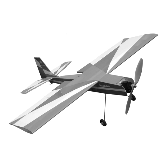
Surge 400
A radio-controlled model is not a toy and is not intended for persons under 16 years old. Keep
this kit out of the reach of younger children, as it contains parts that could be dangerous. A radio-
controlled model is capable of causing serious bodily injury and property damage. It is the buyer's
responsibility to assemble this aircraft correctly and to properly install the motor, radio, and all other
equipment. Test and fly the finished model only in the presence and with the assistance of another
experienced R/C flyer. The model must always be operated and flown using great care and common
sense, as well as in accordance with the Safety Code of the Academy of Model Aeronautics (5151
Memorial Drive, Muncie, IN 47302, 1-800-435-9262). We suggest you join the AMA and become prop-
erly insured prior to flying this model. Also, consult with the AMA or your local hobby dealer to find an
experienced instructor in your area. Per the Federal Communications Commission, you are required
to use only those radio frequencies specified "for Model Aircraft."
Carl Goldberg Products, Ltd. has inspected and certified the components of this aircraft. The company urges the buyer to perform
his own inspection, prior to assembly, and to immediately request a replacement of any parts he believes to be defective for their
intended use. The company warrants replacement of any such components, provided the buyer requests such replacement with-
in a period of 10 days from the date of purchase and provided the defective part is returned, if so requested by the company.
No other warranty, expressed or implied, is made by the company with respect to this kit. The buyer acknowledges and under-
stands that it is his responsibility to carefully assemble the finished flying model airplane and to fly it safely. The buyer hereby
assumes full responsibility for the risk and all liability for personal or property damage or injury arising out of the buyer's use of the
components of this kit.
CARL GOLDBERG PRODUCTS, LTD.
P.O. Box 818 Oakwood GA 30566 Phone #678-450-0085 Fax # 770-532-2163 www.carlgoldbergproducts.com
WARNING
LIMITED WARRANTY
Advertisement
Table of Contents

Related Manuals for Carl Goldberg Products Surge 400


Summary of Contents for Carl Goldberg Products Surge 400
- Page 1 LIMITED WARRANTY Carl Goldberg Products, Ltd. has inspected and certified the components of this aircraft. The company urges the buyer to perform his own inspection, prior to assembly, and to immediately request a replacement of any parts he believes to be defective for their intended use.
- Page 2 COVERING Before you begin assembling your Surge 400 ARF, take The Surge 400 ARF is covered in a polyester film chosen some time to read through this entire instruction book. It is for its beauty, toughness, and ease of application and designed to take you step-by-step through the process and repair.
- Page 3 ITEMS NEEDED TO COMPLETE THIS AIRCRAFT Caution: 5 CHANNEL RADIO WITH 6 MICRO SER- VOS. (WE USED 6 CHANNEL FUTABA RADIO WITH S3108 SERVOS AND GREAT PLANES ELECTRICFLY RECEIVER W/O Before starting, care- SPEED CONTROL) 6” SERVO “Y” HARNESS fully go over all high 6”...
- Page 4 Installing Ailerons & Flaps Servo Extensions Gather the following items: Collect the following parts: (2) 6" Servo Extension wires (1) Wing (2) 12" Servo Extension wires (2) Ailerons ( Left & Right) (2) Flaps ( Left & Right) (1) Wing (10) Mini CA hinges (4) Servos (1) Electrical tape...
- Page 5 Stabilizer Flap & Aileron Pushrods Collect the following parts: Collect the following parts: (1) Fuselage (1) Wing (1) Stabilizer & Elevator (4) Control Horns (1) wing (4) EZ connectors with screws and nylon nuts. (1) 4-40 x 3/4” Socket Head Bolt (4) Short Pushrod Wires (1) #4 Washer Remove the covering on both the ailerons &...
-
Page 6: Fin & Rudder Installation
Locate the slot in one side of the elevators near the center. Remove the covering over the slot. Glue the Nylon control horn into the slot mak- ing sure that the elevator is placed on the work bench as shown in the previous picture. Take the long wire pushrod and insert the end into the pushrod tubing inside the fuselage next to the servo tray. -
Page 7: Landing Gear
Locate the slot in the rudder near the bottom. Remove the covering over the slot. Attach the EZ connector to the control horn with the adjusting screw facing down. Glue the Nylon control horn into the slot mak- ing sure that the rudder control horn is on the opposite side from the elevator control horn. - Page 8 Installing Motor & ESC Collect the following parts: (1) Fuselage (1) Motor with Gear Drive (Not Included) (1) Electronic Speed Control (Not Included) (1) Screw for motor installation (Not Included) Insert the speed control receiver wire through the hole next to the landing gear. Note: Read the instructions that come with your motor and speed control for proper wiring.
-
Page 9: Radio Installation
Radio Installation Battery Installation Collect the following parts: Collect the following parts: (1) Fuselage (1) Fuselage (2) Micro Servos with Hardware (Not Included) (1) 3 cell Li-Po Battery (1) Micro Receiver (Not Included) (2) Servo “Y” Harness (Not Included) Hole Insert foam into the front battery compart- Mount the elevator and rudder servo as ment.
Need help?
Do you have a question about the Surge 400 and is the answer not in the manual?
Questions and answers