Table of Contents
Advertisement
Quick Links
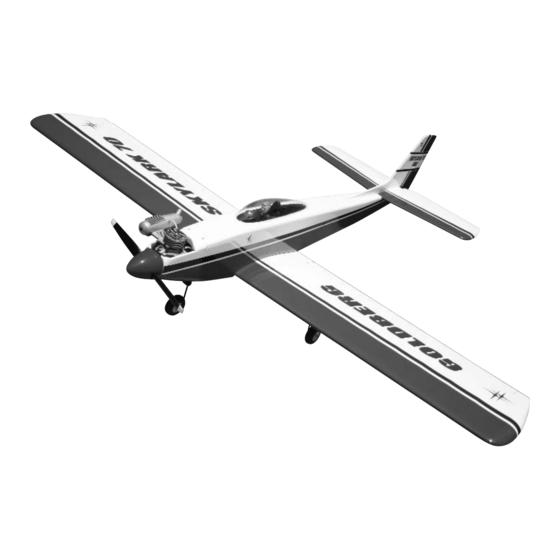
Skylark 70 ARF
INSTRUCTIONS
Designed as a first low-wing trainer over 26 years ago it is still a terrific everyday sport plane, the Skylark 70
ARF combines docile flight characteristics with the aptitude for super-smooth, exciting aerobatics. This ARF
has been designed to keep building time to a minimum; it's 90% pre-built, with premium covering.
through these instructions, follow them carefully, and you'll soon be flying a terrific plane. The better you get
the more fun it gives you!
A radio-controlled model is not a toy and is not intended for persons under 16 years old. Keep
this kit out of the reach of younger children, as it contains parts that could be dangerous. A radio-
controlled model is capable of causing serious bodily injury and property damage. It is the buyer's
responsibility to assemble this aircraft correctly and to properly install the motor, radio, and all other
equipment. Test and fly the finished model only in the presence and with the assistance of another
experienced R/C flyer. The model must always be operated and flown using great care and common
sense, as well as in accordance with the Safety Code of the Academy of Model Aeronautics
(www.modelaircraft.org). We suggest you join the AMA and become properly insured prior to flying this
model. Also, consult with the AMA or your local hobby dealer to find an experienced instructor in your
area. Per the Federal Communications Commission, you are required to use only those radio frequen-
cies specified "for Model Aircraft."
Carl Goldberg Products has inspected and certified the components of this aircraft. The company urges the buyer to perform his
own inspection, prior to assembly, and to immediately request a replacement of any parts he believes to be defective for their
intended use. The company warrants replacement of any such components, provided the buyer requests such replacement with-
in a period of 90 days from the date of purchase and provided the defective part is returned, if so requested by the company.
No other warranty, expressed or implied, is made by the company with respect to this kit. The buyer acknowledges and under-
stands that it is his responsibility to carefully assemble the finished flying model airplane and to fly it safely. The buyer hereby
assumes full responsibility for the risk and all liability for personal or property damage or injury arising out of the buyer's use of the
components of this kit.
CARL GOLDBERG PRODUCTS, LTD.
P.O. Box 818 Oakwood GA 30566 Phone #678-450-0085 Fax # 770-53-63 www.carlgoldbergproducts.com
© Copyright 2004 Carl Goldberg Products LTD.
WARNING
LIMITED WARRANTY
So read
TM
Advertisement
Table of Contents

Related Manuals for Carl Goldberg Products Skylark 70 ARF


Summary of Contents for Carl Goldberg Products Skylark 70 ARF
- Page 1 LIMITED WARRANTY Carl Goldberg Products has inspected and certified the components of this aircraft. The company urges the buyer to perform his own inspection, prior to assembly, and to immediately request a replacement of any parts he believes to be defective for their intended use.
- Page 2 USING THIS INSTRUCTION MANUAL ITEMS NEEDED TO COMPLETE THIS AIRCRAFT Before you begin assembling your Skylark 70 ARF, take RADIO GUIDANCE SYSTEM (4 CHANNEL some time to read through this entire instruction book. It is MINIMUM REQUIRED, 5 STANDARD SER-...
- Page 3 PUSHRODS: Obviously, pushrods should be installed to operate freely, so that they place no load on the servo. The Skylark 70 ARF is covered in a premium polyester Using a servo's power to move a tight rod or heavy surface...
-
Page 4: Wing Assembly & Installation
WING ASSEMBLY & INSTALLATION Slide the aileron toward the wing until no gap AILERON INSTALLATION remains between the aileron and the wing. Carefully check the alignment of the aileron. There should be about 1/32" on both ends. When satisfied with the alignment, remove the straight pins, being sure to keep the aileron tight to the wing. -
Page 5: Aileron Control Horn Installation
Collect the following items (2) Large control horn with back plate (4) 3/4" screw (2) Metal metal clevis (2) 10” threaded rod (2) Swivel keepers Plug the servo extension wire into the servo . Gently pull the string out of the aileron servo hole and tie it or tape it to the servo wire. -
Page 6: Push Rod Installation
Mark wire Fuselage Make sure the aileron is in neutral (level) posi- tion, mark where the wire meets the hole on Locate the landing gear slots in the bottom of the servo arm. the wing and remove the covering material. Remove the wire and cut it about 1/2"... - Page 7 Slide the heat shrink tubing over the pushrod and shrink using a blow drier. Glue the tubing to the wood pushrod using thin CA glue. This finishes the elevator pushrod. Repeat for the rudder pushrod. Make a 90 degree bend. INSTALLING PUSHRODS Cut the wire 1/4”...
- Page 8 Insert the wire into the hole in the right side of the fuselage. Repeat these steps for the rudder pushrod making it exit the left side of the fuselage. Tape the pushrods to the side of the fuselage inside the wing saddle area. WING INSTALLATION ON FUSELAGE Slide the aluminum wing tube into one wing As with the wing and ailerons, use a modeling...
- Page 9 Make sure the stab is level (parallel) with the wing and insert paper strip shims under the low side of the stab, if necessary. Remove the stab & fin from the fuse. Spread epoxy on both the bottom of the stab, fin and the fuselage where the fin will rest.
-
Page 10: Control Horn Installation
MARK HOLE LOCATIONS Insert a straight pin in the center of 3 CA Position the control horn so that the metal cle- hinges. vis holes are right next to the hinge line, as shown. Slide the hinges halfway into the rudder and then slide the entire assembly into the hinge Using a 3/32"... -
Page 11: Nose Gear Installation
Forward NOSE GEAR INSTALLATION OLLECT THE FOLLOWING PARTS (1) Nose gear strut (3) Wheel Collars and set screws (1) Wheel (1) Nose gear steering arm (1) 1.5mm x 43 cm wire and tube (1) EZ connector and screw (1) Nylon Swivel Keeper Tape the elevator so that it stays in the neutral position. -
Page 12: Engine Installation
Slide the steering arm on the top of the nose gear strut. There is a flat spot on the front side of the strut rotate the strut till it is pointing backwards and the set screw aligns with the flat spot Tighten the screw in the steering arm as shown above. - Page 13 Left side of the fuselage Place the mount into the front of the fuselage. Make sure that the smaller side beam is on the left side of the fuselage. Mark the location of the engine mounting The motor mount should point a little to the holes.
-
Page 14: Throttle Push Rod Installation
Install the T-nuts on the bottom side of the mount. Bolt the engine to the mount plate. Re-install the engine and plate into the fuse. Mark the location of the six holes you drilled in the plate on the beams. Drill a 3/32”... -
Page 15: Installing Fuel Tank
Insert the 3mm screw through the center hole in the large washer, through the center hole in the rubber washer against the large side, and screw the small washer on the back side. Attach the two pieces of 5mm tubing to the two tank outlets. - Page 16 RADIO SWITCH, RECEIVER, BATTERY COCKPIT, CANOPY AND PILOT The pilot figure included with your airplane adds an extra touch of realism. APPLY DABS OF GLUE AT JOINTS WHEN DRY, REMOVE TAPE AND COMPLETE We mounted the receiver and battery in front GLUING of the servo tray.
- Page 17 APPLYING DECAL BALANCING IMPORTANT: NEVER NEGLECT THIS STEP WITH ANY AIRPLANE. If you try to fly a plane with the balance point behind the recommended range, you run the risk of having an unstable aircraft and the strong likelihood of a crash. TAKE THE TIME TO PROPERLY BALANCE YOUR MODEL! To determine the Center of Gravity, measure back on 3-1/2"...
- Page 18 You can then work your way up to the higher set- result of practice. The crisp, graceful movements tings. The settings for the SKYLARK 70 ARF are: come from the pilot's willingness to do and do it again. HIGH Don't give up;...
Need help?
Do you have a question about the Skylark 70 ARF and is the answer not in the manual?
Questions and answers