Table of Contents
Advertisement
Quick Links
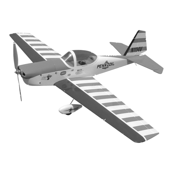
C C h h i i p p m m u u n n k k
A radio-controlled model is not a toy and is not intended for persons under 16 years old. Keep
this kit out of the reach of younger children, as it contains parts that could be dangerous. A radio-
controlled model is capable of causing serious bodily injury and property damage. It is the buyer's
responsibility to assemble this aircraft correctly and to properly install the motor, radio, and all other
equipment. Test and fly the finished model only in the presence and with the assistance of another
experienced R/C flyer. The model must always be operated and flown using great care and common
sense, as well as in accordance with the Safety Code of the Academy of Model Aeronautics (5151
Memorial Drive, Muncie, IN 47302, 1-800-435-9262). We suggest you join the AMA and become prop-
erly insured prior to flying this model. Also, consult with the AMA or your local hobby dealer to find an
experienced instructor in your area. Per the Federal Communications Commission, you are required
to use only those radio frequencies specified "for Model Aircraft."
Carl Goldberg Products, Ltd. has inspected and certified the components of this aircraft. The company urges the buyer to perform
his own inspection, prior to assembly, and to immediately request a replacement of any parts he believes to be defective for their
intended use. The company warrants replacement of any such components, provided the buyer requests such replacement with-
in a period of 10 days from the date of purchase and provided the defective part is returned, if so requested by the company.
No other warranty, expressed or implied, is made by the company with respect to this kit. The buyer acknowledges and under-
stands that it is his responsibility to carefully assemble the finished flying model airplane and to fly it safely. The buyer hereby
assumes full responsibility for the risk and all liability for personal or property damage or injury arising out of the buyer's use of the
components of this kit.
CARL GOLDBERG PRODUCTS, LTD.
P.O. Box 818 Oakwood GA 30566 Phone #678-450-0085 Fax # 770-532-2163 www.carlgoldbergproducts.com
WARNING
LIMITED WARRANTY
400
Advertisement
Table of Contents

Related Manuals for Carl Goldberg Products Chipmunk 400


Summary of Contents for Carl Goldberg Products Chipmunk 400
- Page 1 LIMITED WARRANTY Carl Goldberg Products, Ltd. has inspected and certified the components of this aircraft. The company urges the buyer to perform his own inspection, prior to assembly, and to immediately request a replacement of any parts he believes to be defective for their intended use.
- Page 2 COVERING Before you begin assembling your Chipmunk 400 ARF, The Chipmunk 400 ARF is covered in a polyester film cho- take some time to read through this entire instruction book. sen for its beauty, toughness, and ease of application and It is designed to take you step-by-step through the process repair.
- Page 3 ITEMS NEEDED TO COMPLETE THIS AIRCRAFT Caution: 4 CHANNEL RADIO WITH 4 MICRO SER- VOS. (WE USED 4 CHANNEL FUTABA RADIO WITH S3108 SERVOS AND GREAT PLANES ELECTRIFLY RECEIVER W/O Before starting, care- SPEED CONTROL) 6” SERVO “Y” HARNESS fully go over all high 6”...
- Page 4 Wing JOINING THE WING Spread epoxy on the joiner Put additional epoxy in the joiner pockets and in the dowel hole and spread a thin layer of epoxy along one side of the entire center joint area. Immediately proceed to the next step. Working rapidly, so that the epoxy does not set before you are finished, slide the wing joiner into one wing pocket.
- Page 5 Installing Ailerons Aileron Servo Extensions Gather the following items: Collect the following parts: (1) Wing (2) 6" Extension wires (2) Ailerons ( Left & Right) (1) Wing (6) Mini CA hinges (2) Servos (1) Electrical tape Locate the pre-cut aileron hinge slots in both Plug one 6"...
-
Page 6: Aileron Control Horns
Find the small aileron pushrod wire, and place a “z” in one end. Connect the pushrod connector to the servo arm. Push the extension in the servo hole, SLOW- Put the “Z” bend in to the top hole of the con- LY pull until the end of the 6"... -
Page 7: Elevator Installation
Stabilizer Collect the following parts: (1) Fuselage (1) Stabilizer & Elevator (1) wing (1) 4-40 x 1/2” Socket Head Bolt (1) Wooden Washer covered in red “X” “X” Measure from the end of the wing to the tip of the stab. This measurement should be the same for both sides. -
Page 8: Fin & Rudder Installation
Glue the Nylon control horn into the slot mak- ing sure that the elevator is placed on the work bench as shown in the previous photo. Remove the rudder from the fin and glue the fin to the fuselage making sure to keep the fin perpendicular to the stabilizer. -
Page 9: Landing Gear
Landing Gear Collect the following parts: (1) wing (2) Main Landing Gear Wire (4) 2mm x 6 Sheet Metal Screw Place the wire though the back side of the wheel pants. Insert the wheel into the wheel pant. Push the landing gear wire through the wheel and out the other side of the wheel pant. - Page 10 Tail Wire 2-2/3” Collect the following parts: (1) Fuselage (1) Tail Skid Wire (1) 2mm x 3mm Sheet Metal Screw We have assembled the motor and gear drive that was provided with the Ultrafly system by the manufactures instructions. Slide the gear drive onto the motor stick till the rear of the prop drive is 2-3/4 away from the firewall.
-
Page 11: Radio Installation
Radio Installation Battery Installation Collect the following parts: Collect the following parts: (1) Fuselage (1) Fuselage (2) Micro Servos with Hardware (Not Included) (1) Wing (1) Micro Receiver (Not Included) (1) 4-40 x 3/4 Socket head bolt (1) Servo “Y” Harness (Not Included) (1) 3 cell Li-Po Battery (2) Mini- Pushrod Connectors Rudder... -
Page 12: Control Setup
Control Set Up Propeller Turn on your transmitter and plug in the receiver battery. Center all the control surfaces (rudder, elevator & aileron). If required by your speed control this is the time to program it for your use. Control Travel Aileron up / down 1/2”...
Need help?
Do you have a question about the Chipmunk 400 and is the answer not in the manual?
Questions and answers