RTS TM-2000 User Manual
Trunk master mini-trunk master switch over panel interconnect panel
Hide thumbs
Also See for TM-2000:
- User manual (22 pages) ,
- User manual (32 pages) ,
- User manual (15 pages)

Related Manuals for RTS TM-2000


Summary of Contents for RTS TM-2000
- Page 1 TM-2000 Trunk Master MTM-2000 Mini-Trunk Master SWP-2000 Switch Over Panel ICP-2000 Interconnect Panel User Manual MTM-2000 TM-2000 SWP-2000 ICP-2000 9350-7715-000 Rev H 4/2008...
- Page 2 This package should include the following: Technical questions should be directed to: Customer Service Department Quantity Description Part Number RTS/Telex Communications, Inc. TM-2000 Final Assembly 90107715000 12000 Portland Avenue South Burnsville, MN 55337 USA TM-2000 User Manual 93507715000 Telephone: 800-392-3497...
-
Page 3: Table Of Contents
Trunking Connections and Setup ..........................12 Licensing for the TM-2000/MTM-2000 ........................15 Software Organization ............................15 Hardware Requirements ............................15 ..................................15 ERIAL ORTS ................................15 THERNET DAPTERS TM-2000/MTM-2000 Software Installation Configuration Options ...............16 Updating the TM-2000/MTM-2000 Software ......................17 .................................23 ECOMMENDED ABLES USEFUL LINUX TRICKS ......................... 25... -
Page 5: Description And Specification
The RTS Trunking System consists of an RTS Model TM-2000/MTM-2000 and one or more RTS Model ICP-2000 Interconnect Panels, depending on the number or intercom systems to be trunked. A backup TM-2000/MTM-2000 may also be added to prevent downtime in the event of a failure of the main master control unit. When both main and backup control units... -
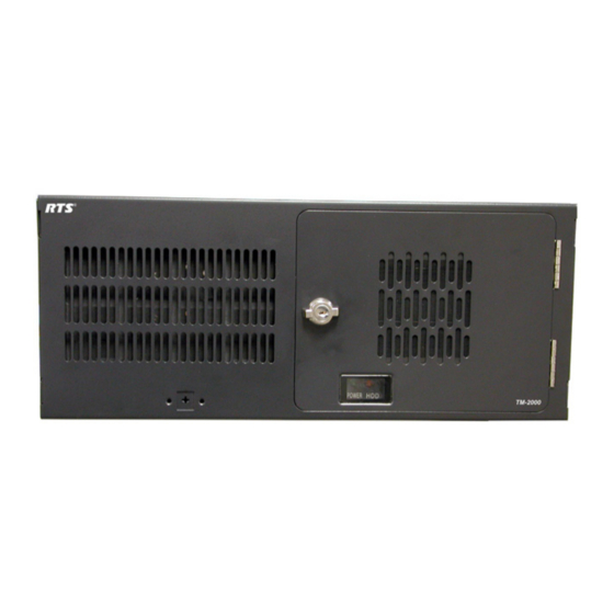
Page 6: Front Panel Features
Front Panel Features TM-2000 front panel features. (Drawing not to scale) FIGURE 1. Status indicators for power, hard drive. Power switch (front) Front security panel NOTE: Press and hold the power switch for five (5) Cooling fans (2) seconds to turn off power. -
Page 7: Rear Panel Features
Rear Panel Features TM-2000 rear panel features (Drawing not to scale FIGURE 2. Power supply fan Card slots containing: (a) RS-485 communication card(s) using SCSI type II connector. See note Power switch (rear) below. (b) Networking connector using RJ-45 AC power connector connector. -
Page 8: Icp-2000 Description
ICP-2000 Description The ICP-2000 is a 1RU breakout panel that converts the SCSI type II connection provided from the TM-2000/MTM-2000 communication card(s) into 9-pin D-Sub connections. Each RS-485 communication card on the TM-2000/MTM-2000 has eight ports provided on the SCSI type II connector. The ICP-2000 breaks these eight ports into individual 9-pin D-sub connections. -
Page 9: Front Panel Features
LED indicates activity on the TM-2000/MTM-2000 (either A or B) is active. Standby TM/MTM LED indicates which TM-2000/MTM-2000 (either A or B) is in standby. Other TM/MTM LED indicates green if TM/MTM B is talking, red if not, and off if the system is not configured for a backup TM-2000/MTM- 2000. -
Page 10: Understanding Trunking
TM-2000 and the MTM-2000 is the number of intercom systems it can communicate with. The TM-2000 supports up to 32 ports (see the NOTE below), whereas the MTM-2000 can support up to 16 ports. Once the interconnections are completed, the trunk master is programmed, using TrunkEdit, to recognize the individual intercom systems. -
Page 11: Specifications
Specifications TM-2000 NOTE: When powering the TM-2000 unit down, press and hold the power switch for 5 seconds to turn off power. Height..................................7”(177.8mm) Width ..................................19.0”(483mm) Depth .................................. 17.7”(449.58mm) Weight ................................35.6 lbs.(16.15kg) Power: ............................... 115/230 VAC, 50/60 Hz, 7A MTM-2000 Height.................................. -
Page 13: Swp-2000
Three serial ports are required if an AutoTIMS unit is to be monitored by TrunkSupervisor. TrunkEdit works with a PC attached to COM port 1 of the TM-2000/MTM-2000 or via the TRK EDIT port of the SWP-2000. TrunkSupervisor works with a PC attached to COM port 2 of the TM-2000/MTM-2000 or via the TRK SPVR port of the SWP-2000. -
Page 14: Trunking Connections And Setup
Identify the correct wiring diagram for your system. For non-redundant TM-2000/MTM-2000 systems, use example sys- tem Figure 8 on page 18. For redundant TM-2000/MTM-2000 systems use the example in Figure 9 on page 19. Connect the trunking system components using the appropriate wiring diagram. Consult the appropriate figures as indicated in Figures 10 and 11 for specific cable wiring diagrams. - Page 15 9600 should be selected. • Select the RS-485 COM port to be used from the TM-2000/MTM-2000 to each intercom system. The COM port can be changed by right-clicking anywhere along an intercom system’s entry in the table. A pop-up menu will display.
- Page 16 • Within each intercom system, assign keypanel keys as required to communicate with destinations in other intercom systems. This is similar to assigning keys in the local intercom system, except that you will have to select an intercom system first when making assignments. Click the KP button on the toolbar to access keypanel setup.
-
Page 17: Licensing For The Tm-2000/Mtm-2000
If it is removed for more than a few minutes, the TM-2000/MTM-2000 will automatically shut down. If a license file is used, the license file is hard-coded to a specific piece of hardware (i.e., TM-2000/MTM-20000). This means the software cannot be used on any other machine than the one it is assigned. -
Page 18: Tm-2000/Mtm-2000 Software Installation Configuration Options
There are many Ethernet Adapter cards that are listed as being supported by Linux; however, in order to support any other cards, the Linux kernel included with the TM-2000/MTM-2000 drivers must first be updated to support the specific Ethernet Adapter card, if it is not already supported. -
Page 19: Updating The Tm-2000/Mtm-2000 Software
Updating the TM-2000/MTM-2000 Software In order to update the TM-2000/MTM-2000, the following files are required: update_tm.sh one or more update files, typically with a name such as to_v830.tgz These must be copied to a DOS-formatted floppy disk. To perform an update, do the following: Log onto the console as the user root. - Page 20 Example of an non-redundant TM-2000 system. FIGURE 8.
- Page 21 Example of a redundant TM-2000 system FIGURE 9.
- Page 22 RJ-45 Connector pinout FIGURE 14. 9-pin D-sub connector pinouts FIGURE 10. DE-9S to DE-9S audio cable FIGURE 15. 25-pin D-sub connector pinout FIGURE 11. 50-pin SCSI type II connector pinout FIGURE 12. DE-9S to unspecified device audio cable FIGURE 16. RJ-11 connector pinout FIGURE 13.
- Page 23 ICP-2000 to ADAM CS RS-485 data cable. FIGURE 21. RJ-11 to DE-9S audio cable FIGURE 17. ICP-2000 to unspecified device RS-485 FIGURE 22. data cable. RJ-11 to RJ-11 audio cable. FIGURE 18. ADAM to unspecified device RS-485 data FIGURE 23. cable.
- Page 24 TM-2000 to TM-2000 network linking FIGURE 25. (standard networking crossover) cable. TM-2000 to SWP-2000 parallel port status FIGURE 26. and control cable.
-
Page 25: Recommended Cables
FIGURE 27. be purchased pre-made from a computer dealer. Use an RS-232 wired “Straight Through” for SWP-2000 to TM-2000 connections. Use a RS-232 wired “Null Modem” for PC to TM-2000/SWP-2000 connection. For TM-2000 to ICP-2000. RS-485 cables use the supplied cables. -
Page 27: Useful Linux Tricks
Each keystroke scrolls forward and back by half of a screen. The TM-2000/MTM-2000 is configured with two virtual consoles. Normally, everything is done on the first virtual console. However, Alt+F2 can be used to switch to a second virtual console (the first time you do this, you will be at another login prompt);...
Need help?
Do you have a question about the TM-2000 and is the answer not in the manual?
Questions and answers