RTS TM-2000 User Manual
Trunking system
Hide thumbs
Also See for TM-2000:
- User manual (22 pages) ,
- User manual (28 pages) ,
- User manual (15 pages)

Related Manuals for RTS TM-2000


Summary of Contents for RTS TM-2000
- Page 1 TM-2000 Trunk Master MTM-2000 Mini-Trunk Master SWP-2000 Switch Over Panel ICP-2000 Interconnect Panel User Manual MTM-2000 TM-2000 SWP-2000 ICP-2000 Rev. 12 AUGUST/2012 F.01U.193.264...
- Page 2 TM-2000 & MTM-2000 User Manual ROPRIETARY OTICE The product information and design disclosed herein were origi- nated by and are the property of Bosch Security Systems, Inc. Bosch reserves all patent, proprietary design, manufacturing, repro- duction, use and sales rights thereto, and to any article disclosed therein, except to the extent rights are expressly granted to others.
-
Page 3: Important Safety Instructions
TM-2000 & MTM-2000 User Manual Important Safety Instructions Read these instructions. Keep these instructions. Heed all warnings. Follow all instructions. Do not use this apparatus near water. Clean only with dry cloth. Do not block any ventilation openings. Install in accordance with the manufacturer’s instructions. - Page 4 TM-2000 & MTM-2000 User Manual Bosch Security Systems, Inc. Rev. 12 F.01U.193.264 User Manual...
-
Page 5: Table Of Contents
Trunking Connections and Setup ......................12 Software Organization ...........................15 Hardware Requirements .........................15 Serial Ports ................................. 15 Ethernet Adapters .............................. 15 TM-2000/MTM-2000 Software Installation Configuration Options .............16 Checking IRQ Assignments ........................17 TM-2000 Trunk Master Software Installation ..................17 Updating the TM-2000/MTM-2000 Software ..................20 Recommended Cables ............................26 USEFUL LINUX TRICKS ...................... - Page 6 TM-2000 & MTM-2000 User Manual User Manual F.01U.193.264 Bosch Security Systems, Inc. Rev. 12...
-
Page 7: Description And Specification
(1) larger system.) The RTS Trunking System consists of an RTS Model TM-2000/MTM-2000 and one (1) or more ICP-2000s, depending on the number of intercom systems to be trunked. A backup TM-2000/MTM-2000 may also be added to prevent downtime in the event of a failure of the main master control unit. -
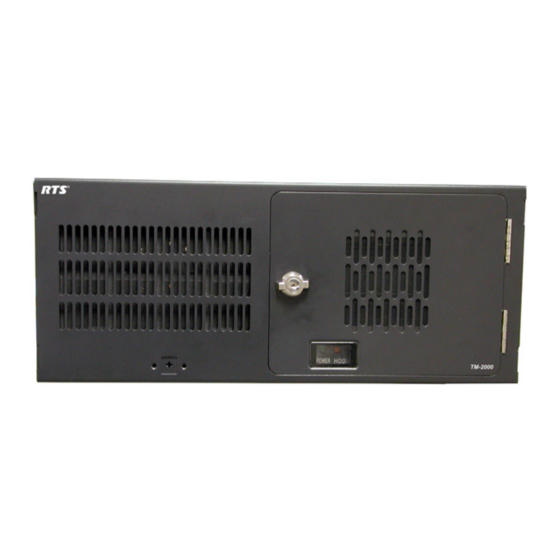
Page 8: Front Panel Features
4 Description and Specification TM-2000 & MTM-2000 User Manual Front Panel Features TM-2000 front panel features. (Drawing not to scale) FIGURE 1. User Manual Bosch Security Systems, Inc. F.01U.193.264 Rev. 12... -
Page 9: Rear Panel Features
NOTE: Press and hold the power switch for five (5) seconds to turn off power. System reset switch. Floppy Drive (used only for factory service). CD-ROM drive. Rear Panel Features TM-2000 rear panel features (Drawing not to scale) FIGURE 2. Power supply fan Power switch (rear) AC power connector... -
Page 10: Icp-2000 Description
9-pin D-sub connections. There are two (2) MDR connectors on the ICP-2000. These two (2) connectors allow both a primary and redundant TM-2000/MTM-2000 to be connected. The connectors are wired in parallel, so it does not matter which connector the primary TM-2000/MTM-2000 and (if present) the redundant TM-2000/MTM2000 are plugged into. The ICP-2000’s connectors are labelled from left to right J1, J2, J3,..J8. -
Page 11: Swp-2000 Description
The SWP-2000 is a 1RU switch-over panel that provides common connections for TrunkEdit and TrunkSupervisor software packages (via serial connections to a Windows-based PC), status monitoring of both TM-2000/MTM-2000 units and control of both TM-2000/MTM-2000 units when used in a redundant configuration. - Page 12 TrunkEdit Connector - Provides connection to the COM port of the extra PC running TrunkEdit software. Trunk Master A TrunkSupervisor Connects to COM port 2 of the TM-2000/MTM-2000 assigned to be Connector - Trunk Master A. Trunk Master A TrunkEdit...
-
Page 13: Understanding Trunking
Trunk Master for exchange of system control signals. The main difference between the TM-2000 and the MTM-2000 is the number of intercom systems it can communicate with. The TM-2000 supports up to 31 ports (see the note below), whereas the MTM-2000 can support up to 16 ports. Once the interconnections are completed, the Trunk Master is programmed, using TrunkEdit, to recognize the individual intercom systems. -
Page 14: Specifications
TM-2000 & MTM-2000 User Manual Specifications TM-2000 NOTE: When powering the TM-2000 unit down, press and hold the power switch for five (5) seconds to turn power off. Height ..................................7” (177.8mm) Width ..................................19.0” (483mm) Depth ................................. 17.7” (449.58mm) Weight ................................35.6lbs (16.15kg) -
Page 15: Installation
Three (3) serial ports are required if an AutoTIMS unit is to be monitored by TrunkSupervisor. TrunkEdit works with a PC attached to COM port 1 of the TM-2000/MTM-2000 or via the TRK EDIT port of the SWP-2000. TrunkSupervisor works with a PC attached to COM port 2 of the TM-2000/MTM-2000 or via the TRK SPVR port of the SWP-2000. -
Page 16: Trunking Connections And Setup
Identify the correct wiring diagram for your system. For non-redundant TM-2000/MTM-2000 systems, use example system Figure 5 on page 21. For redundant TM-2000/MTM-2000 systems use the example in Figure 6 on page 22. Connect the trunking system components using the appropriate wiring diagram. Consult the appropriate figures as indicated in Figure 9 on page 23 and Figure 10 on page 23 for specific cable wiring diagrams. - Page 17 For remote trunked systems (i.e. connected via a leased line, fiber, etc.), 9600 should be selected. Select the RS-485 COM port to be used from the TM-2000/MTM-2000 to each intercom system. NOTE: The COM port can be changed by right-clicking anywhere along an intercom system’s entry in the table. A pop-up menu is displayed.
- Page 18 Set Cascade Flag or Clear Cascade Flag from the pop-up menu that appears. Repeat this procedure for each intercom system audio trunk line needed. Send the changes to the TM-2000/MTM-2000 and save the file. Open AZedit. Within each intercom system, assign keypanel keys as required to communicate with destinations in other intercom systems.
-
Page 19: Software Organization
The choice to enable VDP is made during the software installation. Ethernet Adapters The TM-2000 supports the use of a single Ethernet adapter. This is used for active/standby communications and for TrunkEdit communications via Ethernet. NOTE: If TrunkEdit via Ethernet is used, the computers must be connected by a switch or a hub;... -
Page 20: Tm-2000/Mtm-2000 Software Installation Configuration Options
TM-2000/MTM-2000 Software Installation Configuration Options NOTE: A keyboard and a monitor connected to an external PC connected to the TM-2000/MTM-2000 is required to perform the software installation. When the option to install the software is selected, the computer prompts for different pieces of information: “Is the computer to be part of an active/standby configuration?”... -
Page 21: Checking Irq Assignments
Checking IRQ Assignments The PCI architecture is designed to allow multiple PCI cards to share an interrupt line. The TM-2000 software allows multiple RS-485 cards to share an interrupt. However, an interrupt line which is used by an RS-485 card must not be shared with another device. - Page 22 18 Installation TM-2000 & MTM-2000 User Manual To install TM-2000 Trunk Master software, do the following: Reboot the TM-2000 with the Trunk Master Software CD in the CD-ROM drive. The TM-2000 Trunk Master Software prompt screen appears. TM-2000 Trunk Master Software Options: Run a demo version of the TM-2000 off the CD.
- Page 23 TM-2000 & MTM-2000 User Manual Installation 19 Press Enter () to confirm your selection. If the hard drive has been previously formatted, The hard drive is already formatted, with a partition table window appears. The hard drive is already formatted, with a partition table.
-
Page 24: Updating The Tm-2000/Mtm-2000 Software
This copies the files to the hard drive. When the update is complete, remove the CD. Update complete. you must now reboot the computer in order to restart the TM-2000 message appears. Enter the command unmount /cd. Remove the CD from the drive. - Page 25 Example of an non-redundant TM-2000 system. FIGURE 5.
- Page 26 Example of a redundant TM-2000 system FIGURE 6.
- Page 27 TM-2000 & MTM-2000 User Manual Installation 23 RJ-45 Connector pinout 9-pin D-sub connector pinouts FIGURE 7. FIGURE 11. 25-pin D-sub connector pinout FIGURE 8. DE-9S to DE-9S audio cable FIGURE 12. 50-pin MDR connector pinout FIGURE 9. DE-9S to unspecified device audio cable FIGURE 13.
- Page 28 24 Installation TM-2000 & MTM-2000 User Manual ICP-2000 to unspecified device RS-485 data FIGURE 19. RJ-11 to RJ-11 audio cable. FIGURE 15. cable. ADAM to unspecified device RS-485 data FIGURE 20. Unspecified device to RJ-11 audio cable. FIGURE 16. cable.
- Page 29 TM-2000 & MTM-2000 User Manual Installation 25 TM-2000 to SWP-2000 parallel port status FIGURE 23. and control cable. TM-2000 to ICP-2000 RS-485 COM ports. FIGURE 24. Bosch Security Systems, Inc. User Manual F.01U.193.264 Rev. 12...
-
Page 30: Recommended Cables
PC (TrunkEdit/TrunkSupervisor) to FIGURE 25. Use a RS-232 wired “Null Modem” for PC to TM- TM-2000 or SWP-2000 RS-232 data cable. 2000/SWP-2000 connection. For TM-2000 to ICP-2000, RS-485 cables use the • supplied cables. For TM-2000 to SWP-2000 status/control cables •... -
Page 31: Useful Linux Tricks
Each keystroke scrolls forward and back by half of a screen. The TM-2000/MTM-2000 is configured with two (2) virtual consoles. Normally, everything is done on the first virtual console. However, Alt+F2 can be used to switch to a second virtual console (the first time you do this, another login prompt appears);... - Page 32 Bosch Security Systems, Inc. 12000 Portland Avenue South Burnsville, MN 55337 U.S.A. www.boschcommunications.com...
Need help?
Do you have a question about the TM-2000 and is the answer not in the manual?
Questions and answers