Table of Contents
Advertisement
Quick Links
Advertisement
Table of Contents

Related Manuals for RTS Two-Wire Intercom Series


Summary of Contents for RTS Two-Wire Intercom Series
- Page 1 Model SAP612 Source Assign Panel User Manual 9350-6872-00 Rev E April 2007...
- Page 2 Lincoln, NE 68507 U.S.A. Attn: Service USTOMER UPPORT This package should include the following: Technical questions should be directed to: Customer Service Department RTS/Telex Communications, Inc. DESCRIPTION PART NO. 12000 Portland Avenue South Final Assembly, SAP612 90106872-00 Burnsville, MN 55337 USA...
-
Page 3: Table Of Contents
Table Contents Description and Specification ..........................3 Description ..............................3 Specifications ..............................4 Reference View ............................5 Installation and Operation .............................7 Mechanical Installation ..........................7 Electrical Installation ..........................7 Power ................................7 Using TW Power Supplies ...........................7 Using Other Power Sources ........................7 System Capacity ............................8 Intercom Channels ............................8 Program Sources ............................8 Operation ..............................9 Diagrams and Drawings ............................11... -
Page 5: Description And Specification
CHAPTER 1 Description and Specification Description The Model SAP612 Source Assign Panel independently assigns each of 24 TW channels (12, two-channel TW user station strings) to any one of six busses, or common channels. All channels assigned to a common buss channel can intercommunicate and exchange call signals. -
Page 6: Specifications
Impedance: 600 Ohms Level: 0 dBm Power Requirements No external power required; power distributed from RTS Systems power supplies PS15 or PS31 connected at rear panel of SAP612. Size (H x W x D) 1.72 in. (44mm) x 19 in.(483mm) x 8 in. (204mm) Allow another four (4) inches (102mm) depth for cables on the rear panel. -
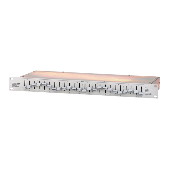
Page 7: Reference View
Reference View Reference View SAP-612 Reference View FIGURE 2. - Page 8 Description and Specification...
-
Page 9: Installation And Operation
Using TW Power Supplies Connect TW power supplies (such as the RTS Models PS8 or PS15) to the CH 1-6 INPUT jacks on the back of the SAP612. One to three power supplies may be connected. Using more than one power supply not only increases the system capacity, but also offers more flexibility in channel assignment. -
Page 10: System Capacity
Installation and Operation Connecting a Non-TW Power Source FIGURE 3. System Capacity To determine power supply loading, add together all of the user stations that will be powered from a particular buss (less stations which are self-powered). NOTE: The SAP612 distributes DC power, but uses no power itself. Refer to the power supply manual for power supply capacity information. -
Page 11: Operation
Operation Operation The front panel of the SAP612 contains 12 pairs of switches; one pair for each user station string. The user station strings 1-12 are identified along the bottom of the panel. Buss numbers 1-6 are identified to the right of each pair or switches. Assign an intercom channel to a buss by setting the appropriate switch to the desired buss number. - Page 12 Installation and Operation...
-
Page 13: Diagrams And Drawings
CHAPTER 3 Diagrams and Drawings AS6867 Assembly Drawing, Connector Board, Model SAP612 AS6866 Assembly Drawing, Front Panel Switch Board SD6872 Schematic Diagram, Source Assign Panel, Model SAP612... - Page 14 Diagrams and Drawings...
- Page 15 FIGURE 4. AS6867 - Assembly Drawing, Connector Board...
- Page 16 FIGURE 5. AS6866 - Assembly Drawing, Front Panel Switch Board...
- Page 17 FIGURE 6. SD6872 - Schematic Diagram, Source Assign Panel Model SAP612...
Need help?
Do you have a question about the Two-Wire Intercom Series and is the answer not in the manual?
Questions and answers