Table of Contents
Advertisement
Quick Links
Advertisement
Table of Contents

Related Manuals for RTS ROAMEO TR-1800


Summary of Contents for RTS ROAMEO TR-1800
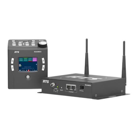
- Page 1 ROAMEO Wireless Intercom System TR‑1800, AP‑1800 User Manual...
-
Page 3: Table Of Contents
ROAMEO Wireless Intercom System Table of contents | en Table of contents Important information Copyright and Disclaimer Notices Important Safety Instructions Certification Information 1.4.1 1.4.2 Industry Canada 1.4.3 Europe Introduction Features Controls and connections 2.2.1 TR-1800 2.2.2 AP-1800 Frequencies of operation System overview System description Access points... - Page 4 en | Table of contents ROAMEO Wireless Intercom System 5.5.3 Belt clip installation and removal 5.5.4 Subscribe the TR-1800 and connect to the AP-1800 Basic operation Intercom keys and displays Display icons Operation of buttons with auto-functions Adjust the volume Basic intercom key operation 6.5.1 Receive a call from an assigned alpha...
-
Page 5: Roameo Wireless Intercom System Table Of Contents | En
ROAMEO Wireless Intercom System Table of contents | en Icon help Scroll list AP-1800 overview Front panel description Software requirements IPedit main screen 8.3.1 Device catalog 8.3.2 Device information 8.3.3 RSTP 8.3.4 Device channel information Troubleshooting Accessories and replacement parts Maintenance 10.1 AP-1800... -
Page 6: Important Information
en | Important information ROAMEO Wireless Intercom System Important information Copyright and Disclaimer All rights reserved. The product information and design disclosed herein were originated by and are the property of Bosch Security Systems, LLC. Bosch reserves all patent, proprietary design, manufacturing, reproduction, use and sales rights thereto, and to any article disclosed therein, except to the extent rights are expressly granted to others. -
Page 7: Important Safety Instructions
ROAMEO Wireless Intercom System Important information | en Warning! To reduce the risk of fire or electric shock, do not expose this apparatus to rain or moisture. Warning! To prevent injury, this apparatus must be securely attached to the floor/wall/rack in accordance with the installation instructions. -
Page 8: Certification Information
22. Use only the manufacturer’s supplied charger to charge the batteries. Certification Information 1.4.1 The RTS TR-1800 and AP-1800 devices are accepted under United States Federal Communications Commission Part 15. This device complies with Part 15 of the FCC. Operation is subject to the following two conditions: –... -
Page 9: Industry Canada
RF exposure compliance. 1.4.2 Industry Canada The RTS TR-1800 and AP-1800 are certified to Industry Canada RSS-213 and ICES-003. This device complies with Industry Canada license exempt RSS standard(s). Operation is subject to the following two conditions: –... - Page 10 en | Important information ROAMEO Wireless Intercom System The full EC Declaration of Conformity for the TR-1800 and AP-1800 may be found at the following website: www.rtsintercoms.com. This equipment is in compliance with: – The Radio Equipment Regulations 2017 – The Electromagnetic Compatibility Regulations 2016 –...
-
Page 11: Introduction
Beltpack users can roam freely within the coverage area without worry of losing communication. ROAMEO uses a standard IP infrastructure as a backbone. RTS recommends the exclusive use of managed switches through the IP network. Each TR-1800 ROAMEO beltpack is fully addressable and is conveniently programmed using the same software for configuring RTS wired keypanels. -
Page 12: Controls And Connections
en | Introduction ROAMEO Wireless Intercom System Controls and connections 2.2.1 TR-1800 2.2.1.1 Controls 9 10 11 12 Bottom A U X I / O S W U P D AT E C H A R G E H E A D S E T Front Back Figure 2.1: TR1800 Reference view... - Page 13 ROAMEO Wireless Intercom System Introduction | en Description Ground Microphone Headphone + Headphone - Headphone - (tied to pin 4) Notice! Most XLR headsets use dynamic-type microphones that work well with radiated RF energy. However, some XLR headsets use Electret microphones that are susceptible to RF energy and can generate audio noise.
- Page 14 en | Introduction ROAMEO Wireless Intercom System Headset Mode The headset accepts 3.5 mm iPhone-like TRRS (Tip, Ring 1, Ring 2, Sleeve) connector Item Description Headphone - Ring 1 Headphone + Ring 2 Ground Sleeve Microphone (+5 VDC bias supplied) USB Jack - Type A Description +5 (only powered in firmware download...
- Page 15 ROAMEO Wireless Intercom System Introduction | en 2.2.2 AP-1800 2.2.2.1 Controls Figure 2.3: AP-1800 Reference view Mounting tabs Reset button Mounting holes (for use with Ethernet connector (x2) optional clamp kit) Optical connector (accepts small form Power connector factor pluggable SFP transceiver) Power LED indicator (for more Antenna (x2) information, see AP-1800, page 127)
-
Page 16: Frequencies Of Operation
en | Introduction ROAMEO Wireless Intercom System Description Data 3 - Data 2- Data 4 + Data 4 - Fiber Optic Connector The fiber optic connector accepts small Form Factor Pluggable (SFP) transceivers: – Single Mode (SM) SFP Module (F.01U.278.502) –... - Page 17 ROAMEO Wireless Intercom System Introduction | en RF Carrier Number Carrier Frequency, MHz Where Used 1881.972* Europe, Singapore, Austrailia 1921.536 US, Canada, Mexico 1923.264 US, Canada, Mexico 1924.992 US, Canada, Mexico 1926.720 US, Canada, Mexico 1928.448 US, Canada, Mexico Table 2.1: ETSI defined RT Channels for DECT * Most common carriers used in the world.
-
Page 18: System Overview
en | System overview ROAMEO Wireless Intercom System System overview System description A ROAMEO wireless intercom system consists of two types of devices: a wireless beltpack (TR-1800) and an access point (AP-1800). The ROAMEO system can be configured for anything from small systems, one access point and a few beltpacks, to a large system, hundreds of access points and hundreds of beltpacks. -
Page 19: Roaming
ROAMEO Wireless Intercom System System overview | en Figure 3.1: Components of a ROAMEO system Home AP The Home AP is any AP-1800 that configures the beltpack’s BPID (Beltpack ID) to one of its available OMNEO channels using IPedit. Visitor AP The Visitor AP is any AP-1800 that does not configure the BPID to one of the OMNEO channels in IPedit. - Page 20 en | System overview ROAMEO Wireless Intercom System Figure 3.2: Simple Roaming diagram When access points boot, they scan the area and pick an RF carrier and time slot based upon the other beacons detected in the area. The access points also avoid using carriers and time slots already in use by using AP IDs (access point identification).
- Page 21 ROAMEO Wireless Intercom System System overview | en Figure 3.3: High density roaming Home Connections Notice! When configuring home connections, assign the configured access point channels to the OMI card in the Matrix. For more information, see Connect the access point to the intercom, page 43.
-
Page 22: System Drawings
en | System overview ROAMEO Wireless Intercom System DECT RF link to the Home AP is maintained until the new DECT RF link to the Visitor AP is confirmed. When the connection is confirmed, the existing DECT RF link is dropped and the new OMNEO channel from the Visitor AP is used. - Page 23 ROAMEO Wireless Intercom System System overview | en Figure 3.7: Small system - G.726 or G.726-EX coverage for a single area Figure 3.8: Small system - G.722 or G.722-EX coverage over two areas Bosch Security Systems, LLC 2023-12 | V04 | F.01U.343.141 User Manual...
- Page 24 en | System overview ROAMEO Wireless Intercom System Medium Systems Figure 3.9: Medium system - G.722 or G.722-EX coverage over two areas and between Figure 3.10: Medium system - G.726 or G.726-EX coverage over one large area 2023-12 | V04 | F.01U.343.141 Bosch Security Systems, LLC User Manual...
-
Page 25: Roameo System Setup Checklist
ROAMEO Wireless Intercom System System overview | en Large Systems Figure 3.11: Large system - G.722 or G.722-EX coverage over three areas Figure 3.12: Large system - G.726 or G.726-EX coverage over one large area ROAMEO system setup checklist – Each beltpack has only one HOME access point. Bosch Security Systems, LLC 2023-12 | V04 | F.01U.343.141 User Manual... - Page 26 en | System overview ROAMEO Wireless Intercom System – Each system can have only one active Primary Sync Master access point, which is set in IPedit. – When subscribing a beltpack to the system, the beltpack must be within 40 feet (12 meters) of an access point in that system.
-
Page 27: Site Survey
ROAMEO Wireless Intercom System Site Survey | en Site Survey Site Survey is the application (standard on the TR-1800) used to plan and design the ROAMEO system. Site survey provides crucial information on roaming coverage. With the ROAMEO site survey application, finding coverage areas for access points is easier to accomplish, even though obstacles are encountered, such as metal walls, reinforced concrete, metal-coated glass, etc. - Page 28 en | Site Survey ROAMEO Wireless Intercom System Click Change Adapter Settings. Double-click Local Area Connection or Ethernet. Click Properties. The Local Area Connection Properties screen appears. Select Internet Protocol Version 4 (TCP/IPv4). Click Properties. Select the Use the following IP Address check box. The IP fields become editable.
-
Page 29: Set Up An Existing System With A Dynamic Ip Address
ROAMEO Wireless Intercom System Site Survey | en 4.1.3 Set up an existing system with a dynamic IP address Notice! Set the computer to obtain an IP address automatically. The DHCP server for the matrix must be enabled in the AZedit application before the computer delivers an IP address. To connect the AP-1800 to the matrix, do the following: 1. -
Page 30: Assign The Tr-1800 To An Ap-1800 Channel
en | Site Survey ROAMEO Wireless Intercom System 4.1.5 Assign the TR-1800 to an AP-1800 channel To assign the TR-1800 to an AP-1800 channel, do the following: From the Device Catalog on the left, select the AP-1800. The Device Information fields populate. Select the Sync Master check box to set the AP-1800 to Sync Master. -
Page 31: Perform A Site Survey
ROAMEO Wireless Intercom System Site Survey | en Press the Select button. The focus moves to the next character space in the system ID. Repeat steps 8 and 9 until you enter the complete system ID. Press the Select button. The Enter PIN screen appears. - Page 32 en | Site Survey ROAMEO Wireless Intercom System – You can supply power to the access point at the possible test locations by using power extension cables or battery power. For battery power, 12 VDC @ 0.600 Amps must be available to the access point.
- Page 33 ROAMEO Wireless Intercom System Site Survey | en Site survey screen Description of Site Survey Screen CARRIER The current RF carrier of the access point. This may change from time to time. SLOT The current time slot on the RF carrier the access point to the beltpack packets are located.
- Page 34 en | Site Survey ROAMEO Wireless Intercom System If the two indications are different, always use the worst case of the RSSI and QF indication for defining a good coverage area. Example: QF = 10 and RSSI = 71, use the RSSI level as the cutoff for the good coverage area.
-
Page 35: Installation
ROAMEO Wireless Intercom System Installation | en Installation Access point placement Considerations – Access point placement – System considerations - See System drawings, page 22 – Mounting options – Mounting surfaces – Site survey The placement of access points can be critical for optimal RF performance of the system. When positioning the access points, place them in the best location for maximum, unimpeded coverage of the area. -
Page 36: Mounting Options
en | Installation ROAMEO Wireless Intercom System 5.1.3 Mounting options There are four recommended ways to mount the ROAMEO AP-1800 access point unit: – Wall-mount or ceiling mount – Pole-mount – Rail-mount – Free-standing installation, such as a table or shelf - not shown above Notice! The mounting clamp kit, for rail or pole mounting, sold separately. - Page 37 ROAMEO Wireless Intercom System Installation | en Notice! Newer antennas come with a support washer that improves the strength of the connection of the antenna to the case. You can also use this washer to easily tighten the antenna to the access point case.
- Page 38 en | Installation ROAMEO Wireless Intercom System Carefully bend the antenna 90° at the antenna joint until the antennas are aligned straight up or down. 5.1.4.1 Wall or ceiling mounting To wall mount the ROAMEO AP-1800 access point, do the following: Use the access point and a pencil to mark the four hole locations on the wall or ceiling.
- Page 39 ROAMEO Wireless Intercom System Installation | en Align the AP-1800 in the position and placement desired. Use a screw driver to drive the screws into the predefined holes. 5.1.4.2 Pole mounting To pole mount the ROAMEO AP-1800 access point, do the following: Align the mounting clamp in the pole use position on the bottom of the AP-1800.
- Page 40 en | Installation ROAMEO Wireless Intercom System Fit the mounting clamp around the pole desired. Once in position, use the adjustment knobs to tighten the clamp around the pole. 5.1.4.3 Rail mounting To rail mount the ROAMEO AP-1800 access point, do the following: Align the mounting clamp in the rail use position on the bottom of the AP-1800.
-
Page 41: Ap-1800 Mounting Surfaces
ROAMEO Wireless Intercom System Installation | en 5.1.4.4 Free-standing installation Setting the AP-1800 unit on a table or shelf is commonly referred to as a free-standing installation. When you install the AP-1800 as free-standing, position the antenna perpendicular to the unit (antenna in the air) for the best signal reception. 5.1.5 AP-1800 mounting surfaces You can mount the ROAMEO AP-1800 Access Point on many different surfaces. -
Page 42: Power Over Ethernet
en | Installation ROAMEO Wireless Intercom System Power over Ethernet The access point is tolerant of PoE (Power over Ethernet) voltages on the Ethernet network, but cannot be powered by PoE directly without an add-on accessory kit (see Accessories and replacement parts, page 113). -
Page 43: Connect The Access Point To The Intercom
ROAMEO Wireless Intercom System Installation | en Connect the access point to the intercom 5.4.1 Configure the OMI using AZedit To configure the OMI to the Access Point using AZedit, do the following: From the Status menu in AZedit, select I/O Cards. The I/O Card Status window appears showing a list of installed cards. -
Page 44: Add The Omi To The Device Catalog In Ipedit
en | Installation ROAMEO Wireless Intercom System From the Partner Channel drop down menu, select the channel on the device to which the OMI communicates. When finished, click Apply. Apply sends all the changes to all the cards in the intercoms or click Cancel to discard all the changes made. -
Page 45: Add The Ap-1800 To Ipedit
ROAMEO Wireless Intercom System Installation | en 5.4.4 Add the AP-1800 to IPedit To add the AP-1800 to IPedit, do the following: Start IPedit. From the Devices menu, select Add. The Add Devices window appears. From the Available Devices pane, select the Access Point. The Add button becomes active. - Page 46 en | Installation ROAMEO Wireless Intercom System Notice! All access points in a system must have the same System ID. Enter the unique AP ID for the access point. The range for this field is 1-254. Select the Primary DECT Sync check box if the access point is the master for the entire system.
-
Page 47: Configure The Tr-1800 To Its Home Ap-1800
ROAMEO Wireless Intercom System Installation | en – Expand the tree to view the available destination devices. – Select the destination device. – Click OK. The Discovered Devices window closes. 16. Select the destination channel to which the channel is connected. 17. - Page 48 en | Installation ROAMEO Wireless Intercom System – Quick charge charging via the CHG-1800 LI4 4-bay battery charger – In-device charging 5.5.1.1 Quick charge Charging the battery in the 4-bay quick charger requires about 2.5 hours to completely charge a fully discharged battery. Once charging is complete, you can leave the batteries on the charger indefinitely.
-
Page 49: Battery Installation And Removal
ROAMEO Wireless Intercom System Installation | en To charge the battery in the beltpack, do the following: Power off the beltpack. On the bottom of the beltpack, attach the power cable to the charge connector. Plug the wall charger of the power cable into a standard AC wall outlet. Notice! Operation of the beltpack while charging the battery is not supported. -
Page 50: Subscribe The Tr-1800 And Connect To The Ap-1800
en | Installation ROAMEO Wireless Intercom System 5.5.4 Subscribe the TR-1800 and connect to the AP-1800 Notice! An access point must be configured using IPedit before a beltpack can be subscribed with a system. To subscribe the beltpack, do the following: Press the power button to turn the beltpack on. - Page 51 ROAMEO Wireless Intercom System Installation | en Notice! The PIN number default is all zeroes. Using the UP and DOWN buttons, change the first PIN digit field. Notice! The SELECT button advances the focus to the next field. The MENU button goes back one field.
-
Page 52: Basic Operation
en | Basic operation ROAMEO Wireless Intercom System Basic operation Intercom keys and displays Key Assignment Types and Descriptions Point to point (call from one port to another) Party Line (talk/listen to a party line) Interrupt Foldback (interrupt program input to talk to output Special List (call a group of panels) Relay (activate a relay) Camera Isolate (private call) -
Page 53: Display Icons
ROAMEO Wireless Intercom System Basic operation | en Default Color Description Salmon IFB, Talk indicator Pale green Special list Periwinkle UPL resource Table 6.3: Default Color Keys Display icons Notice! There is an internal help menu in the main menu structure to help define the icons used on the beltpack. - Page 54 en | Basic operation ROAMEO Wireless Intercom System Icon Icon Name Description RF Signal The RF Signal icon indicates the RF signal strength the beltpack is receiving. Scroll List The Scroll List icon indicates a scroll list is available. A scroll list displays a list of available users.
- Page 55 ROAMEO Wireless Intercom System Basic operation | en Icon Icon Name Description Key Assignments Use the Key Assignments menu to create, edit, and delete key assignments for the beltpack. System Setup Use the System Setup menu to access the system function options for the beltpack.
- Page 56 en | Basic operation ROAMEO Wireless Intercom System Icon Icon Name Description Top Display Use the Top Display Brightness menu to set the Brightness brightness of the top display. LCD Timeout Use the LCD Timeout menu to configure the LCD timeout on the beltpack.
-
Page 57: Operation Of Buttons With Auto-Functions
ROAMEO Wireless Intercom System Basic operation | en Icon Icon Name Description System Functions System Setup Subscribes the beltpack to the AP-1800. Set Language Sets the language the beltpack displays. Site Survey View site survey information. Diagnostics Displays the beltpack's configuration, such as RSSI strength, access point RF channel, time slot, access point IP address, the CODEC the beltpack is currently using, etc. -
Page 58: Basic Intercom Key Operation
en | Basic operation ROAMEO Wireless Intercom System On the top panel of the beltpack, turn the volume dial clockwise to increase the volume. Turn the volume dial counter-clockwise to decrease the volume. A progression bar appears in the front and top displays showing increases and decreases in volume. -
Page 59: Receive A Call From An Unassigned Alpha
ROAMEO Wireless Intercom System Basic operation | en On the top panel of the beltpack, tap the TALK LED button that corresponds with the keypanel assignment shown on the front panel display. A red talk bar appears on the talk assignment displayed in the front color display. To release a call: On the top panel of the beltpack, tap the TALK LED button that corresponds with the alpha displayed in the front panel display. -
Page 60: Call Waiting Window
en | Basic operation ROAMEO Wireless Intercom System Press the SELECT button. The alpha appears in the call waiting window display. Press and hold the REPLY button to initiate the call. The call is made. The selected assignment ID appears in the call-waiting window. Notice! As long as the REPLY button is held, the audio is sent to the beltpack being called. -
Page 61: Scroll List Shortcut
ROAMEO Wireless Intercom System Basic operation | en Press the SELECT button. A list of assignment types appear on the beltpack display screen. Scroll to the assignment type. Press the SELECT button. A list of available assignments appear in the beltpack display screen. 6.7.1 Scroll list shortcut The Scroll List shortcut takes the user to the scroll list type select screen. - Page 62 en | Basic operation ROAMEO Wireless Intercom System Press and hold the button for at least 0.5 second. Release the button to turn the key off. 6.10 Pages Use Setup Pages to configure additional button assignments on the beltpack. The beltpack has four pages with four button assignments per page, giving a possible 16 assignments available.
-
Page 63: Dark Mode
ROAMEO Wireless Intercom System Basic operation | en Assign a call assignment to a button on the beltpack Notice! Changing pages is not possible if a top panel talk or listen button is active. To assign a call assignment to a button on the beltpack, do the following: On the beltpack, press the MENU button. -
Page 64: Lockout - Front
en | Basic operation ROAMEO Wireless Intercom System While pressing on the MENU button, double-tap the Volume Control knob. Dark Mode exits the top display, while the front display activates. 6.12 Lockout - Front Use Lockout Front to disable the user from accessing the menu and setup areas of the beltpack. -
Page 65: Tr-1800 Overview
ROAMEO Wireless Intercom System TR-1800 overview | en TR-1800 overview System quick start Initial Beltpack Setup – Step 1 Charge the battery. See Battery charge, page 47. – Step 2 Install the battery in the beltpack. See Battery installation and removal, page 49. –... -
Page 66: Select Button
en | TR-1800 overview ROAMEO Wireless Intercom System Notice! Press the MENU button from any menu to exit the menu structure and return to the home screen. To open the menu, do the following: On the front of the keypanel, press the MENU button. The main menu appears. -
Page 67: Talk Button
ROAMEO Wireless Intercom System TR-1800 overview | en To clear a call from the call waiting window, do the following: Press the CLEAR button. The call disappears from the call waiting window. 7.2.8 Talk button The TALK buttons are used to enable audio paths from the headset microphone. The talk light activates when the talk button is active. -
Page 68: Speaker Settings
en | TR-1800 overview ROAMEO Wireless Intercom System Using the UP and DOWN buttons, navigate through the menu options. Press the SELECT button to select a menu. The subMENU icons appear in the beltpack display screen. 7.3.1 Speaker settings Use the Speaker Settings menu to configure the headset being used with the beltpack. From this menu, the Aux Input level, the Aux diminish level, Maximum Volume, and the headset type can be configured. - Page 69 ROAMEO Wireless Intercom System TR-1800 overview | en Press the SELECT button. The speaker setting options appear in the beltpack display screen. Select the AUX Input icon. Press the SELECT button. The Aux Input slider bar becomes active in the beltpack display screen. Adjust the Aux Input, as necessary.
-
Page 70: Mic Menu
en | TR-1800 overview ROAMEO Wireless Intercom System 7.3.1.4 Headset select Use the Headset Select menu to select between a 5-pin XLR connector headset or a 3.5mm connector headset. Figure 7.6: Headset Select icon To select the headset connector, do the following: Select the Speaker icon. - Page 71 ROAMEO Wireless Intercom System TR-1800 overview | en Press the SELECT button. The Mic Gain adjustment slider bar becomes active in the beltpack display screen. Adjust mic gain, as needed. Press the SELECT button to save the modification. Press and hold the MENU button to exit the menu. 7.3.2.2 Sidetone Use the Sidetone menu to adjust the level at which the user hears their own voice in the...
-
Page 72: Brightness
en | TR-1800 overview ROAMEO Wireless Intercom System 7.3.2.4 Hot mic Use the Hot Mic menu to select between a normal operating mic and a hot mic. In Normal mode, audio from the active mic goes out to the Matrix when any talk button is active. In the Hot Mic mode, audio from the mic goes out to the Matrix without regard to the talk key state. - Page 73 ROAMEO Wireless Intercom System TR-1800 overview | en – Dark mode dim switch 7.3.3.1 Talk/listen LED Use the Talk/Listen LED menu to adjust the brightness of the Talk/Listen buttons on the beltpack. Figure 7.11: Talk/Listen LED Brightness icon Brightness ranges from 0% to 100%. By default, Talk/Listen LED brightness is set at 20%.
- Page 74 en | TR-1800 overview ROAMEO Wireless Intercom System Select the Top Display Brightness icon. Press the SELECT button. The brightness adjustment slider becomes active. Adjust the Top Display Brightness, as needed. Press the SELECT button to save the modification. Press and hold the MENU button to exit the menu. 7.3.3.4 LCD timeout The LCD Timeout menu is used to set the amount of time, in seconds, the color front...
- Page 75 ROAMEO Wireless Intercom System TR-1800 overview | en Press the SELECT button to save the modification. Press and hold the MENU button to exit the menu. 7.3.3.6 Screen flip The Screen Flip menu item is used to flip the front display orientation vertically to accommodate for wearing the beltpack on a belt.
- Page 76 en | TR-1800 overview ROAMEO Wireless Intercom System Notice! When the Master Talk Switch is active, Talk and Listen keys function normally. Tapping a talk key turns the key on or off, regardless of the master talk key status. This means no keys are locked in the on or off position.
-
Page 77: Alerts
ROAMEO Wireless Intercom System TR-1800 overview | en Select the Brightness icon. Press the SELECT button. The brightness setting options appear in the beltpack display screen. Using the UP and DOWN arrow buttons, select the Exclusive key icon. Exclusive Keys Tap Key appears in the panel display. Tap each red key to remove the exclusive key option. - Page 78 en | TR-1800 overview ROAMEO Wireless Intercom System – Low Battery – Call Waiting – DECT Connection – Matrix Connection Figure 7.21: Alerts Page 2 Page 2 available menu items – Dark Mode – Boot Alert – Button Clicks 7.3.4.1 Low battery alert The Low Battery alert is used to enable or disable an audio alert when the TR-1800 ROAMEO beltpack has a low battery.
- Page 79 ROAMEO Wireless Intercom System TR-1800 overview | en Enable the low battery alert. The 2-position indicator turns green. Disable the low battery alert. The 2-position indicator turns blue. Press the SELECT button to save the modification. Press and hold the MENU button to exit the menu. 7.3.4.2 Call waiting alert Use the Call Waiting alert to enable or disable the audio alert the user hears when an...
- Page 80 en | TR-1800 overview ROAMEO Wireless Intercom System Press the SELECT button. The alerts menu options appear in the beltpack display screen. Select the DECT connection icon. Press the SELECT button. The DECT connection enable/disable 2-position indicator becomes active. Enable the DECT connection alert. The 2-position indicator turns green.
- Page 81 ROAMEO Wireless Intercom System TR-1800 overview | en a theater production). Even though the CWW top panel backlight is not on, the display shows it is in Dark Mode. In minimal ambient light, this message is seen, however, it may be more difficult with no light.
-
Page 82: Key Assignments
en | TR-1800 overview ROAMEO Wireless Intercom System Enable the key clicks alert. The 2-position indicator turns green. Disable the key clicks alert. The 2-position indicator returns to the original disabled blue. Press the SELECT button to save the modification. Press and hold the MENU button to exit the menu. -
Page 83: System
ROAMEO Wireless Intercom System TR-1800 overview | en Press the SELECT button. The four button assignment columns appear. Navigate to the button column to configure an assignment. Press the SELECT button. A scroll list of assignment types appear. Notice! To clear an entry, select Clear Entry located at the bottom of the assignment type list. Select the assignment type desired. -
Page 84: Set Language
en | TR-1800 overview ROAMEO Wireless Intercom System Figure 7.30: System Setup icon Figure 7.31: System menu screen 7.5.2 Set language Use the Set Language menu item to configure the language of the TR-1800 ROAMEO beltpack. There are ten different languages to available. Figure 7.32: Set Language icon Figure 7.33: Available languages on the TR-1800 Available languages are:... -
Page 85: Site Survey
ROAMEO Wireless Intercom System TR-1800 overview | en Press the SELECT button. The settings menu options appear in the beltpack display screen. Select the Set Language icon. Press the SELECT button. A scrollable list of available languages appears in the beltpack display screen. Select the language desired. -
Page 86: Diagnostics
en | TR-1800 overview ROAMEO Wireless Intercom System AP ID Field The AP ID field displays the ID of the access point currently hosting the beltpack. Access points are assigned a unique number by the user when configuring the system. All access points in the system must have a unique AP ID. - Page 87 ROAMEO Wireless Intercom System TR-1800 overview | en Figure 7.37: Diagnostics screen Access Point To Beltpack Icon The Access Point to Beltpack displays the connection information associated with the current access point to beltpack connection. Some of the information included is the RSSI, QF, the carrier and the slot assignment.
-
Page 88: Software Update
en | TR-1800 overview ROAMEO Wireless Intercom System PMID Field The PMID field is used to display the beltpack’s home access point’s AP ID and the order in which the beltpack was subscribed to the system. For example, in the PMID 000801, the 8 represents the beltpacks Home access point in Hex. -
Page 89: Alpha Size
ROAMEO Wireless Intercom System TR-1800 overview | en To open the software update screen, do the following: Select the Settings icon. Press the SELECT button. The settings menu options appear in the beltpack display screen. Select the Software Update icon. Press the SELECT button. -
Page 90: Versions
en | TR-1800 overview ROAMEO Wireless Intercom System In the Type group drop down menu for Main Panel, select TR-1800/X (where X is the length of the alpha). The number displayed after the TR-1800 defines the alpha length: /4 = Four Character Alpha /4, /4 = Four Character Alpha for Talk and Four Character Alpha for Listen /6 = Six Character Alpha /8 = Eight Character Alpha... -
Page 91: Scroll List
ROAMEO Wireless Intercom System TR-1800 overview | en Brightness Screen Menu The Brightness Screen menu displays all the brightness screen icons shown on the brightness page and their description. Alerts Screen Menu The Alerts Screen menu displays all the alerts screen icons shown on the alerts page and their description. -
Page 92: Ap-1800 Overview
en | AP-1800 overview ROAMEO Wireless Intercom System AP-1800 overview Front panel description Figure 8.1: Front panel - AP-1800 Power LED The Power LED is used to display the status of the AP-1800 – Solid Green - Power/Normal Operation – Blinking Green - Normal Reset Mode –... -
Page 93: Software Requirements
OMI - v6.1.10 and above – ODIN - v1.0.0 and above – OMS - v1.0.1 and above – MCII-e - v3.4.0 and above RTS Software Suite – Use the latest software suite. Find it at www.rtsintercoms.com in the downloads library. IPedit main screen The IPedit Main screen is divided into three sections: –... -
Page 94: Device Catalog
en | AP-1800 overview ROAMEO Wireless Intercom System 8.3.1 Device catalog The Device Catalog lists all available devices in the Matrix system. From this pane, switching between devices is easy. Every device can be displayed and sorted by device type in this pane, making it easier to keep devices organized. - Page 95 ROAMEO Wireless Intercom System AP-1800 overview | en Figure 8.4: Device information Notice! The graphics displayed in these figures are for a ROAMEO device. When a different device is selected, different fields are displayed. For more information, see the IPedit Technical Manual.
- Page 96 en | AP-1800 overview ROAMEO Wireless Intercom System IP Address Field Use the IP Address field to display the IP Address of the selected device. Only when Static IP Addressing is enabled can the IP Address of the selected device be modified. Netmask Field Use the Netmask field to display the Netmask address of the selected device.
- Page 97 ROAMEO Wireless Intercom System AP-1800 overview | en Status Information Group Box Figure 8.6: Status information Type Field The Type field displays the type of device. The two ROAMEO are: – OAP-5 - An OMNEO access point supporting up to five beltpacks (G.722 or G.722-EX CODEC) –...
- Page 98 en | AP-1800 overview ROAMEO Wireless Intercom System – green - the beltpack for that channel is communicating with the access point. – red - the beltpack for that channel is not powered on – no color - no beltpack DECT BPID was entered into the Channel Configuration area. Sync Display Box The Sync display box indicates whether the access point is or is not synced with the master access point.
- Page 99 ROAMEO Wireless Intercom System AP-1800 overview | en Use the PIN field to enter the four-digit PIN (Personal Identification Number) for the access point. The PIN number acts as a level of security, allowing only beltpacks with the correct PIN number to subscribe to that access point. The first time the beltpack is powered up, this number is entered into the beltpack to gain access to the HOME access point (see “First Time Operation - Beltpack”...
- Page 100 100 en | AP-1800 overview ROAMEO Wireless Intercom System The range for this field is 1 through 254. The default for this field is 1. Primary DECT Sync Check Box Use the Primary DECT Sync check box to indicate which access point is designated as the DECT synchronization-timing master for the entire system.
-
Page 101: Rstp
ROAMEO Wireless Intercom System AP-1800 overview | en 101 8.3.3 RSTP RSTP (Rapid Spanning Tree Protocol) is a fault tolerant Ethernet protocol, which allows the system to be set up with multiple Ethernet connection paths to the same access points. This provides a redundant connection if one connection path fails. -
Page 102: Device Channel Information
102 en | AP-1800 overview ROAMEO Wireless Intercom System 8.3.4 Device channel information For more information on the Channel Status sections (below Channel Configuration), see the IPedit Technical manual. Figure 8.8: Channel configuration Channel Configuration Use the Channel Configuration section to configure channel settings for each applicable device. - Page 103 ROAMEO Wireless Intercom System AP-1800 overview | en 103 Notice! This is an editable field. By changing the IP Address, the destination type changes if the destination device type can be determined. Destination Description Field The Destination Description field displays the destination channel’s description, if applicable.
- Page 104 104 en | AP-1800 overview ROAMEO Wireless Intercom System From the Channel column, select the Zone field. Using the number keys on the keyboard, select the desired zones the beltpack can roam and access. To deselect a zone, do the following: Using the number keys on the keyboard, select the zone number to deselect.
-
Page 105: Troubleshooting
ROAMEO Wireless Intercom System Troubleshooting | en 105 Troubleshooting Issue Possible Cause Solution RF range of beltpacks is less Missing access point Verify both antennas than normal antenna(s). attached to the access point are tightly connected. For more information, see Antenna connection and placement, page 36. - Page 106 106 en | Troubleshooting ROAMEO Wireless Intercom System Issue Possible Cause Solution The beltpack is not Ensure the beltpack has a subscribed to the system. Home access point. Verify the access point is in the system where the beltpack's BP ID is entered into on of the channels of the access point.
- Page 107 ROAMEO Wireless Intercom System Troubleshooting | en 107 Issue Possible Cause Solution The matrix has not fully Ensure the matrix is fully booted. booted. This can take several minutes. Ethernet from the access Verify the access points are point to the matrix is down. connected to the matrix.
- Page 108 108 en | Troubleshooting ROAMEO Wireless Intercom System Issue Possible Cause Solution open slots, additional access points may be needed. Power down other beltpacks in the area to test for system improvement. If improvement is seen, additional access points are needed in the area to provide more open slots for additional beltpacks.
- Page 109 ROAMEO Wireless Intercom System Troubleshooting | en 109 Issue Possible Cause Solution of the beltpack to the old access point and new access point. – For consideration, Ethernet traffic on a shared network can cause bandwidth overloading. Take care to plan for bandwidth coverage for the number of beltpacks being used.
- Page 110 110 en | Troubleshooting ROAMEO Wireless Intercom System Issue Possible Cause Solution microphone is plugged in, the dynamic microphone may not work correctly. Microphone audio gain is set The beltpack may have the too low. audio gain set to 0%. To check go to the main menu of the beltpack and select Mic.
- Page 111 ROAMEO Wireless Intercom System Troubleshooting | en 111 Issue Possible Cause Solution No lights or display shown The beltpack is set to Dark Determine if dark mode is on beltpack Mode. active on the beltpack. No lights are visible on the beltpack when dark mode is active, and the CWW display shows Dark Mode.
- Page 112 112 en | Troubleshooting ROAMEO Wireless Intercom System Issue Possible Cause Solution Right click the flash drive. A flyout menu appears. Click Format. The format window appears. From the File System drop down menu, select FAT32. IMPORTANT: All data currently on the drive will be erased when formatting it.
-
Page 113: Accessories And Replacement Parts
ROAMEO Wireless Intercom System Troubleshooting | en 113 Issue Possible Cause Solution Cannot download firmware The computer where the – If the matrix system to the access point FWUT (Firmware Update containing the access Tool) is located is not in the points is configured for same network as the access DHCP addressing, then... - Page 114 114 en | Troubleshooting ROAMEO Wireless Intercom System Name Description Model BP-240 Battery 7.5V, Li-Ion battery for the BP-240 TR-1800 beltpack CHG-1800 LI4 4-Bay 4-bay changer to charge four CHG-1800 LI4 Charger BP-240 Lithium Ion batteries in parallel. The CHG-1800 LI4 replaces the CHG-240.
- Page 115 ROAMEO Wireless Intercom System Troubleshooting | en 115 Name Description Model SM SFP Optical Single Mode (MM) Small OM-SM-FIBER Module Form Factor Pluggable (SFP) optical transceiver module. A 1000Base-LX Ethernet module with up to 10km range on 9/125 μm Single Mode Fiber (SMF) MM SFP Optical Multi Mode (SM) Small OM-MM-FIBER...
-
Page 116: Maintenance
116 en | Maintenance ROAMEO Wireless Intercom System Maintenance 10.1 AP-1800 10.1.1 Update firmware To update the Access Point firmware, do the following: Open the Firmware Upload Tool. From the File menu, select Options. Click the Change button. A network folder appears. Navigate to the folder holding the AP-1800 firmware. -
Page 117: Replace Existing Access Point
ROAMEO Wireless Intercom System Maintenance | en 117 Set the access point to be a Sync Master. 10.1.2.2 Multiple access points To create a system of multiple access points, do the following: Configure each Access Point to the same OMI, OMS, or ODIN; see Connect the access point to the intercom, page 43. - Page 118 118 en | Maintenance ROAMEO Wireless Intercom System In the IP Address field, change the IP Address. The IP Address field turns yellow. Press Enter. Click the Send All Changes icon to send the changes to the matrix. The Send Changes window appears. Verify the changes are correct.
-
Page 119: Add An Access Point To The System
ROAMEO Wireless Intercom System Maintenance | en 119 Click Done. The Send Changes window closes and the Access Point automatically resets. If the connection cannot reestablish communications, reboot the AP-1800. Notice! Each beltpack connected to the Access Point must re-subscribe to the system before it can connect to the access point. -
Page 120: Ap-1800 Reset
120 en | Maintenance ROAMEO Wireless Intercom System Right-click the access point to reboot. A popup menu appears. From the popup menu, select Reboot Device. The device reboots. 10.2 AP-1800 reset 10.2.1 Factory default reset Use the Factory Default Reset to set the access point to the factory defaults. To perform a factory default reset, do the following: Press and hold the reset button for 10 seconds. -
Page 121: Normal Reset
ROAMEO Wireless Intercom System Maintenance | en 121 Release the reset button. Press and hold the reset button for another 10 seconds to confirm the factory default reset. LED starts blinking red, indicating the defaults being restored. Release the reset button. The unit resets and powers up with the factory defaults. -
Page 122: Update The Firmware
122 en | Maintenance ROAMEO Wireless Intercom System Release the reset button and within 3 seconds press and release it again. The LED repeats a red blinking sequence to indicate the unit is running in the TBR-6 test mode. Notice! To get the access point out of TBR-6 test mode, cycle the power to the device. -
Page 123: Tr-1800 Reset
ROAMEO Wireless Intercom System Maintenance | en 123 Press the MENU button again. The MENU icons appear in the beltpack display screen. Navigate to the Settings icon. Press the SELECT button. The Settings submenu icons appear in the beltpack display screen. Navigate to the Update icon. - Page 124 124 en | Maintenance ROAMEO Wireless Intercom System Once the Home screen appears, release the MENU button. The beltpack boots to the home screen. All parameters, except subscription are reset. 2023-12 | V04 | F.01U.343.141 Bosch Security Systems, LLC User Manual...
-
Page 125: Technical Data
ROAMEO Wireless Intercom System Technical data | en 125 Technical data 11.1 TR-1800 General TR-1800 Beltpack Audio Modes G.722 or G.722-EX wideband mode G.726 or G.726-EX narrowband mode Frequency Response (G.722/G.722-EX) (Hz- 165 Hz - 7.0 kHz kHz) Frequency Response (G.726/G.726-EX) (Hz- 255 Hz - 3.6 kHz kHz) Front Backlit Display... -
Page 126: Tr-1800 Beltpack Case
126 en | Technical data ROAMEO Wireless Intercom System TR-1800 Beltpack Headphone impedance (XLR and 3.5mm) 51 - 2000 Ω Microphone Type (XLR jack) Dynamic or Electret auto-detect Microphone Type (3.5mm jack) Electret only (+5 V bias always supplied) In-beltpack charging jack Accepts 2.5 x 5.5 mm charging plug, positive center In-beltpack charging voltage/current... - Page 127 ROAMEO Wireless Intercom System Technical data | en 127 TR-1800 HOLSTER Nylon Holster with Lanyard Color Black Dimensions (H x W x D) (in) 4.50 in x 4 in x 1.50 in Dimensions (H x W x D) (mm) 144.3 mm x 101.6 mm x 38.1 mm 11.3 AP-1800 General...
- Page 128 128 en | Technical data ROAMEO Wireless Intercom System AP-1800 Access point Optical connector Accepts small form factor pluggable SMP modules RF connectors Reverse-SMA-F RF Communications AP-1800 Access point Receiver (RF) frequency range (MHz) 1,920 MHz – 1,930 MHz (NA - North America) 1,880 - 1,900 mHz (EU - Europe, Asia, Australia)
- Page 129 ROAMEO Wireless Intercom System Technical data | en 129 AP-1800 Access point Max. Diameter 0.52 Inch (13.2 mm) Finish Matte black Connector Reverse Polarity SMA Plug Operating temperature -40 °F to 131 °F (-40 °C to 55 °C) AP-1800 Certifications RoHS, FCC Part 15D, FCC Part 15B, FCC/IC Class B device, IC RSS-213, IC ICES-003, EN 301 406, EN 301 489-6, EN 60950-1, RCM, Singapore, Mexico, CE, UKCA Bosch Security Systems, LLC...
-
Page 130: Beltpack Enhanced Diagnostics
130 en | Beltpack enhanced diagnostics ROAMEO Wireless Intercom System Beltpack enhanced diagnostics Beginning in ROAMEO release v8.5.0, the BP includes enhanced diagnostic features to assist with setup and installation of new systems and also help identify issues with existing installations. - Page 131 ROAMEO Wireless Intercom System Beltpack enhanced diagnostics | en 131 Current Connection Information The current connection information for the BP is displayed across the top: DECT Connection Status DECT 2-way communication is established between BP and AP DECT connection No DECT connection APID Access point identifier CH/SLOT...
- Page 132 132 en | Beltpack enhanced diagnostics ROAMEO Wireless Intercom System – When “Allow Full Capacity” is selected in IPedit, an AP becomes full when 5 G.722 (or 10 G.726) beltpacks are connected. This setting does not reserve timeslots to automatically adjust and optimize performance with interference.
-
Page 133: Enhanced Diagnostics Screen Examples
ROAMEO Wireless Intercom System Beltpack enhanced diagnostics | en 133 Enable/Disable Press and hold the SELECT Roaming button for 3 seconds. A roaming disabled icon appears in the lower-right corner of the Enhanced Diagnostics screen when roaming is disabled. Roaming is enabled upon exit of the Enhanced Diagnostics screen. - Page 134 134 en | Beltpack enhanced diagnostics ROAMEO Wireless Intercom System However, roaming is not possible because AP02 is configured with an invalid zone (color= RED) and AP03 is busy/full (color= ORANGE) because it already has the maximum number of beltpacks allowed. The roaming state is “2”...
- Page 136 Bosch Security Systems, LLC 130 Perinton Parkway Fairport, NY 14450 www.rtsintercoms.com © Bosch Security Systems, LLC, 2023 EU importer: Bosch Sicherheitssysteme GmbH Robert-Bosch-Platz 1 70839 Gerlingen Germany © Bosch Sicherheitssysteme GmbH, 2023 202312011659...
Need help?
Do you have a question about the ROAMEO TR-1800 and is the answer not in the manual?
Questions and answers