
Related Manuals for RTS TR-1800


Summary of Contents for RTS TR-1800
- Page 1 ROAMEO Family Wireless Intercom System •TR-1800 •AP-1800 Rev. 01 APRIL/2017 F.01U.306.750...
- Page 2 WARNING: APPARATUS SHALL NOT BE EXPOSED TO DRIPPING OR SPLASHING AND NO OBJECTS FILLED WITH LIQUIDS, SUCH AS VASES, SHALL BE PLACED ON THE APPARATUS. RTS Intercoms ......www.rtsintercoms.com/warranty RTS Digital WARNING: THE MAIN POWER PLUG MUST REMAIN READILY OPER- RTSTW ABLE.
-
Page 3: Important Safety Instructions
ROAMEO System Important Safety Instructions Read these instructions. Keep these instructions. Heed all warnings. Follow all instructions. Do not use this apparatus near water. Clean only with dry cloth. Do not block any ventilation openings. Install in accordance with the manufacturer’s instructions. - Page 4 ROAMEO System Bosch Security Systems, Inc. Rev. 01 Technical Manual F.01U.306.750...
-
Page 5: Table Of Contents
Europe ..............................13 Chapter 2 : Introduction ......................15 General Description ..........................15 Features ..............................15 Controls, Connections, and Specifications ................... 16 TR-1800 Reference View ..........................16 TR-1800 Connections ............................17 XLR - 5-Pin Female ............................17 3.5mm Auxiliary Jack ...........................17 Headset Mode ..............................17 USB Jack - Type A ............................18... - Page 6 Set Up an Existing System with a Static IP Address ..................40 Add the Access Point to IPedit ........................43 Assign the TR-1800 to an AP-1800 Channel ....................44 Subscribe the TR-1800 to the AP-1800 ......................44 Set Up an Existing System with a Dynamic IP Address ................... 46 Perform a Site Survey ..........................46...
- Page 7 ROAMEO System Configure the Beltpack to its Home AP-1800 ....................65 First Time Operation – Beltpack ......................66 Battery Charge ..............................66 Quick Charge ..............................66 4-Bay LED Charge Status Description ....................... 66 In-Device Charging ............................67 Battery Installation and Removal ........................68 Beltclip Installation and Removal ........................
- Page 8 ROAMEO System Front Display Brightness ..........................104 Top Display Brightness ........................... 105 LCD Timeout ..............................105 Call Tally Talk ..............................106 Screen Flip ............................... 106 Master Talk Switch ............................107 Low Battery Alert ............................108 Call Waiting Alert ............................109 DECT Connection Alert ..........................
- Page 9 Beltpack ...............................145 Update the Firmware on the TR-1800 ROAMEO Beltpack ................145 Add a Beltpack to the System ......................... 146 Update the Splash Screen on the TR-1800 ROAMEO Beltpack ..............146 Beltpack Reset ............................147 Factory Reset ..............................147 Settings Reset ..............................147 Bosch Security Systems, Inc.
- Page 10 ROAMEO System Chapter 10 : Troubleshooting, Accessories and Replacements ..........149 Troubleshooting ...........................149 Accessories and Replacement Parts ....................155 Notes ..............................157 Bosch Security Systems, Inc. Technical Manual F.01U.306.750 Rev. 01...
-
Page 11: Chapter 1 : Certification Information
CHAPTER 1 Certification Information The RTS TR-1800 and AP-1800 devices are accepted under United States Federal Communication Commission Part 15. This device complies with Part 15 of the FCC. Operation is subject to the following two conditions: This device may not cause interference. -
Page 12: Industry Canada
(above) must be maintained between the antenna and nearby persons to satisfy RF exposure compliance. Industry Canada The RTS TR-1800 and AP-1800 are certified to Industry Canada RSS-213 and ICES-003. This device complies with Industry Canada license exempt RSS standard(s). Operation is subject to the following two conditions: This device may not cause interference, and •... -
Page 13: Europe
A license may be required to operate this equipment in certain regions! Consult the national authority for possible requirements. The full EC Declaration of Conformity for the TR-1800 and AP-1800 may be found at the following website: www.rtsintercoms.com. Bosch Security Systems, Inc. - Page 14 14 Certification Information ROAMEO System Bosch Security Systems, Inc. Technical Manual F.01U.306.750 Rev. 01...
-
Page 15: Chapter 2 : Introduction
ROAMEO uses a standard IP infrastructure as a backbone, RTS recommends the exclusive use of managed switches through the IP network. Each TR-1800 ROAMEO beltpack is fully addressable and is conveniently programmed using the same software used in RTS wired keypanels. -
Page 16: Controls, Connections, And Specifications
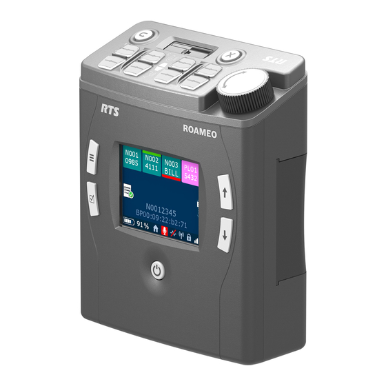
16 Introduction ROAMEO System Controls, Connections, and Specifications TR-1800 Reference View TR-1800 Reference View FIGURE 1. Power button Select button Main Menu button Color Backlit Display - 320 x 240 pixels Scroll Up Navigation button Scroll Down Navigation button Battery Release slide... -
Page 17: Tr-1800 Connections
ROAMEO System Introduction 17 TR-1800 Connections 3.5mm Auxiliary Jack XLR - 5-Pin Female XLR – 5-pin Female Connection FIGURE 2. Description Ground 3.5 mm Tip, Ring, Sleeve diagram FIGURE 3. Microphone Accepts a 3.5mm TRS (Tip, Ring, Sleeve) stereo Headphone +... -
Page 18: Usb Jack - Type A
18 Introduction ROAMEO System USB Jack - Type A Description +5 (only powered in firmware download process) Data- Data + Charging Jack Accepts a 5.5mm x 2.5mm plug with positive center Description Center Accepts 12VDC Shell Technical Manual Bosch Security Systems, Inc. F.01U.306.750 Rev. -
Page 19: Tr-1800 Specifications
Average Power (G.726 narrowband) Top-mounted rotary encoder Individual listen adjustment 4 mW (NA) Talk/Listen Control TR-1800 Beltpack Case (includes removable and adjustable shoulder strap) 4 x Talk and 4 x Listen buttons (top panel) Dimensions Number of Assignment Pages 4 in. x 1.5 in. x 4.5 in. -
Page 20: Ap-1800 Reference View
20 Introduction ROAMEO System AP-1800 Reference View AP-1800 Reference View FIGURE 4. Mounting Tabs Mounting Holes (for use with optional Clamp Kit) Power Connector Power LED Indicator (for more information, see “AP-1800 Specifications” on page 22) Reset Button Ethernet Connector (x2) Optical Connector (Accepts small form factor pluggable SFP modules) Antenna (x2) -
Page 21: Ap-1800 Connections
ROAMEO System Introduction 21 AP-1800 Connections Dual Ethernet Connectors Description Data 1 + Data 1 - Data 2 + Data 3 + Data 3 - Data 2 - Data 4 + Data 4 - Fiber Optic Connector Accepts small Form Factor Pluggable (SFP) transceivers SM (Single Mode) SFP Module (F.01U.278.502) •... -
Page 22: Ap-1800 Specifications
22 Introduction ROAMEO System AP-1800 Specifications Power Maximum Output Power (Peak) General: 200mW (EU) Audio Modes 100mW (NA) G.722 wideband Average Power, load dependent (G.722, wideband) G.726 narrowband 17-83mW (EU) Max. beltpacks per AP-1800 (G.722) Average Power, load dependent (G.726, wideband) 8-83mW (EU) Max. -
Page 23: Frequencies Of Operation
ROAMEO System Introduction 23 Frequencies Of Operation 1880 – 1900 MHz (Europe) 1920 – 1930 MHz (North America) ETSI Defined RF Channels for DECT DECT systems automatically select the best interference-free frequencies on which to operate. Users do not need to do any frequency coordination. - Page 24 24 Introduction ROAMEO System Technical Manual Bosch Security Systems, Inc. F.01U.306.750 Rev. 01...
-
Page 25: Chapter 3 : System Overview
System Overview System Description A ROAMEO wireless intercom system consists of two types of devices: a wireless beltpack (TR-1800) and an access point (AP-1800). The ROAMEO system can be configured for anything from small systems (one access point and a few beltpacks) to a large system (10 access points and up to 40 beltpacks). -
Page 26: Access Points
26 System Overview ROAMEO System Access Points The ROAMEO AP-1800 converts DECT signaling to the OMNEO protocol, Audinate’s Dante digital high-quality audio transport over IP. AP-1800 units are physically connected via the Ethernet network to an ADAM or ADAM-M matrix using an OMI card . -
Page 27: Roaming
ROAMEO System System Overview 27 Roaming The ROAMEO system allows beltpacks to move between the radio coverage area of one AP-1800 to the radio coverage area of another AP-1800. This is called roaming. Roaming is monitored and maintained by the system of access points, making it transparent to the user. - Page 28 28 System Overview ROAMEO System IMPORTANT: It is important if more than six wideband or ten narrowband access points are used to cover the same area that all the access point be placed in a location where they can detect each other. High Density Roaming FIGURE 7.
-
Page 29: Home Connections
ROAMEO System System Overview 29 Home Connections IMPORTANT: When configuring home connections, remember to assign the configured access point channels to the OMI card in the Matrix (see “Connecting the Access Point to the Intercom” on page 59). Each access point channel is a bi-directional OMNEO channel for audio, command, and control with the matrix. For a wideband system (CODEC G.722), there are five access point channels available to assign BPIDs. -
Page 30: Home To Visitor Roaming
30 System Overview ROAMEO System Home to Visitor Roaming When a beltpack roams from its Home AP to a Visitor AP, a new OMNEO connection is made between both access points. However, before the new connection’s OMNEO channel is used, the new DECT RF connection must be confirmed as good. The new DECT RF connection is made before breaking from the old connection. -
Page 31: System Drawings
ROAMEO System System Overview 31 System Drawings These following drawings are basic examples of small, medium and large ROAMEO systems Small System Small System – G.722 Coverage for a Remote Area FIGURE 10. Bosch Security Systems, Inc. Technical Manual F.01U.306.750 Rev. - Page 32 32 System Overview ROAMEO System Small System – G.726 Coverage for a Single Area FIGURE 11. Technical Manual Bosch Security Systems, Inc. F.01U.306.750 Rev. 01...
- Page 33 ROAMEO System System Overview 33 Small System – G.722 Coverage over Two Areas FIGURE 12. Bosch Security Systems, Inc. Technical Manual F.01U.306.750 Rev. 01...
-
Page 34: Medium System
34 System Overview ROAMEO System Medium System Medium System – G.722 Coverage Over Two Areas and Between FIGURE 13. Technical Manual Bosch Security Systems, Inc. F.01U.306.750 Rev. 01... - Page 35 ROAMEO System System Overview 35 Medium System – G.726 Coverage Over One Large Area FIGURE 14. Bosch Security Systems, Inc. Technical Manual F.01U.306.750 Rev. 01...
-
Page 36: Large System
36 System Overview ROAMEO System Large System Large System – G.722 Coverage Over Three Areas FIGURE 15. Technical Manual Bosch Security Systems, Inc. F.01U.306.750 Rev. 01... - Page 37 ROAMEO System System Overview 37 Large System – G.726 Coverage Over One Large Area FIGURE 16. Bosch Security Systems, Inc. Technical Manual F.01U.306.750 Rev. 01...
-
Page 38: Roameo System Setup Checklist
38 System Overview ROAMEO System ROAMEO System Setup Checklist ❐ Each beltpack has only one HOME access point. ❐ Each system can have only one Sync Master access point (set in IPedit). ❐ When subscribing a beltpack to the system, the beltpack must be within 40 feet (12 meters) of an access point in that system. -
Page 39: Chapter 4 : Site Survey
Site Survey Description Site Survey is the application (standard on the TR-1800) used to plan and design the ROAMEO system. Site survey provides crucial information on roaming coverage. With the ROAMEO site survey application, finding coverage areas for access points, even when obstacles are encountered, such as metal walls, reinforced concrete, metal-coated glass, etc. is easier to accomplish. -
Page 40: Set Up An Existing System With A Static Ip Address
40 Site Survey ROAMEO System Set Up an Existing System with a Static IP Address To set the computer to a Link Local IP Address, do the following: IMPORTANT: These instructions detail a typical setup for the Windows 7 platform. NOTE: If the AP-1800 has been connected to a Matrix system in the past or assigned a static IP Address already, then assigning the computer a Link Local Address will not work. - Page 41 ROAMEO System Site Survey 41 Click Network and Sharing Center. The Network and Sharing Center window appears. Click Change Adapter Settings. The Network Connections window appears. Double-click Local Area Connection. The Local Area Connection Status window appears. Bosch Security Systems, Inc. Technical Manual F.01U.306.750 Rev.
- Page 42 42 Site Survey ROAMEO System Click Properties. The Local Area Connection Properties window appears. From the connection list, select Internet Protocol Version 4 (TCP/IPv4). Technical Manual Bosch Security Systems, Inc. F.01U.306.750 Rev. 01...
-
Page 43: Add The Access Point To Ipedit
ROAMEO System Site Survey 43 Click the Properties button. The Internet Protocol Version 4 (TCP/IPv4) Properties window appears. Select the Use the following IP Address check box. The IP fields become active. In the IP Address: field, enter 169.254.0.1. In the Subnet mask: field, enter 255.255.0.0. Click the OK button to exit the Internet Protocol Properties window. -
Page 44: Assign The Tr-1800 To An Ap-1800 Channel
The access point appears in the Device Catalog in the left pane. Click Done. Assign the TR-1800 to an AP-1800 Channel To assign the TR-1800 to an AP-1800 channel, do the following: From the Device Catalog on the left, select the AP-1800. The Device Information fields populate. - Page 45 ROAMEO System Site Survey 45 Using the up and down arrow buttons, navigate to the System Setup icon. Press the Select button. The Subscription Setup screen appears with the system setup icon highlighted. Press the Select button. The Enter system ID screen appears. NOTE: If the beltpack had been subscribed to an access point previously, the last system ID used populates the screen.
-
Page 46: Set Up An Existing System With A Dynamic Ip Address
Using IPedit, configure the OMI card with the AP-1800 unit. NOTE: If the AP-1800 being used is already part of an operating system and a TR-1800 is subscribed to it, then no more IP configuration is required. Turn off all other AP-1800 devices in the system so coverage of the single access point being tested can be found. -
Page 47: Description Of Site Survey Screen
ROAMEO System Site Survey 47 Using the up and down arrow buttons, navigate to the System Setup icon. Press the SELECT button. The beltpack system setup menu appears. Using the up and down arrow buttons, navigate to the Site Survey icon. Press the SELECT button. -
Page 48: Description Of Qf
48 Site Survey ROAMEO System Description of QF Color Description Weak - too many dropouts in the area Yellow Marginal - some dropouts of audio in the area 7-10 Green Strong - good RF coverage Mark the access point’s location on the building layout diagram. Walk around with the beltpack throughout the area(s) of interest while looking at the site survey screen. -
Page 49: Chapter 5 : Installation
CHAPTER 5 Installation Access Point Placement Considerations Access Point Placement • System Considerations - See System Drawings Chapter • Mounting Options • Mounting Surfaces • Site Survey • Access Point Placement The placement of access points can be critical for optimal RF performance of the system. When positioning the access points, place them in the best location for maximum, unimpeded coverage of the area. -
Page 50: Mounting Options
50 Installation ROAMEO System Mounting Options Mounting Options FIGURE 17. There are four recommended ways to mount the ROAMEO AP-1800 access point unit: Wall or ceiling mount • pole mount • rail mount • free-standing installation (such as a table or shelf) – not shown above •... -
Page 51: Antenna Connection And Placement
ROAMEO System Installation 51 Antenna connection and placement Antennas should be in the upright-most position for the best reception of signal. The antenna has a joint to adjust the angle, if needed. To attach the antennas to the ROAMEO AP-1800, do the following: Gently push the antenna into the antenna connector on the ROAMEO AP-1800. - Page 52 52 Installation ROAMEO System To adjust the antennas for the best signal reception when the access point is mounted horizontally, do the following: Carefully bend the antenna 90° at the antenna joint until the antennas are aligned straight up or down. >...
-
Page 53: Wall Or Ceiling Mounting
ROAMEO System Installation 53 Wall or Ceiling Mounting To wall mount the ROAMEO AP-1800 access point, do the following: Using the access point and a pencil, mark the four hole locations on the wall or ceiling. NOTE: It may be necessary to predrill the holes or use screw anchors, depending on the material of the wall. Align the AP-1800 in the position and placement desired. -
Page 54: Pole Mounting
54 Installation ROAMEO System Pole Mounting To pole mount the ROAMEO AP-1800 access point, do the following: Align the mounting clamp in the pole use position on the bottom of the AP-1800. Using the supplied screws from the mounting kit, attach the mounting clamp to the AP-1800. Fit the mounting clamp around the pole desired. -
Page 55: Free-Standing Installation
ROAMEO System Installation 55 Using the supplied screws from the clamp kit, attach the mounting clamp to the AP-1800. Fit the mounting clamp around the rail. Once in position, use the larger adjustment knob to tighten the clamp around the pole. Free-Standing Installation Setting the AP-1800 unit on a table or shelf is commonly referred to as free-standing installation. -
Page 56: Ap-1800 Mounting Surfaces
56 Installation ROAMEO System AP-1800 Mounting Surfaces The ROAMEO AP-1800 Access Point can be mounted to many different surfaces. Using Table 2, determine the proper mounting surface and mounting materials needed. Mounting Surfaces and Materials TABLE 2. Mounting Surface Materials Used Drywall Drywall screws Drywall anchors (as needed) -
Page 57: Power Over Ethernet
ROAMEO System Installation 57 Power Over Ethernet The access point is tolerant of PoE (Power Over Ethernet) voltages on the Ethernet network, but cannot be powered by PoE directly without an add-on accessory kit (see “Accessories and Replacement Parts” on page 155). The add-on accessory kit can be used when combined with an existing PoE (802.3af) or PoE+ (802.3at) managed Ethernet switch to provide power to the access point from the Ethernet network. -
Page 58: Power Up The Ap-1800 Access Point
58 Installation ROAMEO System Power Up the AP-1800 Access Point To connect and configure the access point to the matrix, do the following: Using an Ethernet cable or an optical fiber cable, connect the access point to the Matrix via a network switch. NOTE: Either Ethernet port can be used. -
Page 59: Connecting The Access Point To The Intercom
ROAMEO System Installation 59 Connecting the Access Point to the Intercom The OMI card is configured using AZedit and IPedit; however, only IPedit can be used to configure the access point. IMPORTANT: Verify the computer is connected to the same network as the Intercom Matrix frame. Configure the OMI using AZedit To configure the OMI to the Access Point using AZedit, do the following: From the Status menu in AZedit, select I/O Cards. -
Page 60: Add The Omi To The Device Catalog In Ipedit
60 Installation ROAMEO System Add the OMI to the Device Catalog in IPedit To add the OMI to IPedit, do the following: Open IPedit. From the Device menu, select Add. The Add Devices Window appears, open to the Search tab. Select the OMI card. -
Page 61: Add The Ap-1800 To Ipedit
ROAMEO System Installation 61 Add the AP-1800 to IPedit Start IPedit. From the Devices menu, select Add. The Add Devices window appears. From the Available Devices pane, select the Access Point. The Add button becomes active. Click Add. The AP-1800 appears in the device catalog in the left panel. Click Done. -
Page 62: Configure The Ap-1800 In Ipedit
62 Installation ROAMEO System Configure the AP-1800 in IPedit To configure the Access Point with IPedit, do the following: IMPORTANT: The user must be signed in to IPedit with network administrator rights to complete these instructions. From the Device Catalog on the left, select the AP-1800. The Device Information pane populates. - Page 63 ROAMEO System Installation 63 In the PIN field, enter the PIN of the access point. By default, this field is set to 0000. From the Zone drop down menu, select the zone the access point is assigned. By default the zone is set to 0 From the CODEC drop down menu, select the CODEC the access point is running.
- Page 64 64 Installation ROAMEO System In the Destination Device Name field, enter the name of the OMI card to which the channel is connected. Click the browse button. The Discovered Devices window appears. Expand the tree to view the available destination devices. From the expanded tree, select the destination device.
-
Page 65: Configure The Beltpack To Its Home Ap-1800
ROAMEO System Installation 65 Configure the Beltpack to its Home AP-1800 To assign a beltpack to an access point channel, do the following: From the Device Catalog on the left, select the AP-1800. The Channel Configuration populates. Power up the beltpack. The BP ID displays on the front panel. -
Page 66: First Time Operation - Beltpack
Charging is complete To quick charge the batteries, do the following: Ensure the TR-1800 is powered off and remove the battery. See “Battery Installation and Removal” on page 68. Plug the 4-bay battery charger into a standard AC wall outlet. -
Page 67: In-Device Charging
ROAMEO System Installation 67 In-Device Charging The TR-1800 is also capable of charging the battery while the battery is still installed in the beltpack. It takes approximately eight hours to fully charge a completely discharged battery. NOTE: The CH 4 talk button on the top of beltpack indicates the charge status. -
Page 68: Battery Installation And Removal
68 Installation ROAMEO System Battery Installation and Removal Battery Installation and Removal FIGURE 18. To install the battery in the beltpack, do the following: Align the battery with the battery slot on the beltpack. Carefully slide the battery into the slot until it clicks in place (3). To remove the battery from the beltpack, do the following: Verify the beltpack is powered off. -
Page 69: Beltclip Installation And Removal
(1). A click is felt/heard when the beltclip is securely in place. On the back panel of the TR-1800 beltpack, while lifting up on the tension clip up, carefully slide the beltclip out of the beltclip track (2). Bosch Security Systems, Inc. -
Page 70: Subscribe The Beltpack And Connect To The Access Point
NOTE: A subscribed beltpack can access this setup screen through the beltpack menus. For more information, see “Subscribe the TR-1800 to the AP-1800” on page 44. From the System Setup screen, press the SELECT button on the front of the beltpack. - Page 71 ROAMEO System Installation 71 NOTE: The PIN number default is all zeroes. Using the UP and DOWN buttons, change the first PIN digit field. NOTE: The SELECT button advances the focus to the next field. The MENU button goes back one field. Press the SELECT button.
- Page 72 72 Installation ROAMEO System Technical Manual Bosch Security Systems, Inc. F.01U.306.750 Rev. 01...
-
Page 73: Chapter 6 : Basic Operation
CHAPTER 6 Basic Operation Intercom Keys and Displays Key Assignment Types and Descriptions PP = Point to Point (call from one port to another) PL = Party Line (talk/listen to a party line) IFB = Interrupt Foldback (interrupt program input to talk to output) SL = Special List (call a group of panels) RY = Relay (activate a relay) ISO = Camera Isolate (private call) -
Page 74: Color Display Descriptions For Intercom Keys
ROAMEO System Color Display Descriptions for Intercom Keys The TR-1800 front displays uses key colors to distinguish the type of key assignment programmed for each key. Use Table 3 to help determine the available key assignment colors. Default Color Keys TABLE 3. -
Page 75: Display Icons
ROAMEO System Basic Operation 75 Display Icons IMPORTANT: Located in the beltpack menu structure is an internal help menu to help define the icons used on the beltpack. Table 4: Icon Descriptions Icon Icon Name Description Home Screen Home Screen The Home Screen icon is a navigational marker indicating home screen is displayed. - Page 76 76 Basic Operation ROAMEO System Table 4: Icon Descriptions Icon Icon Name Description Screen Flip The Screen Flip icon is used to flip the orientation of the front display screen for easy viewing when the beltpack is clipped to pants or a belt. Use the up and down arrow buttons to navigate to the flip screen icon in the page list.
- Page 77 ROAMEO System Basic Operation 77 Table 4: Icon Descriptions Icon Icon Name Description Scroll List The Scroll List menu is used to access the different scroll lists available. Scroll lists make searching for particular key assignments easier by grouping the assignments by type. For more information, see “Scroll List”...
- Page 78 78 Basic Operation ROAMEO System Table 4: Icon Descriptions Icon Icon Name Description Backlights and LEDs LED Intensity The Talk/Listen LED menu item is used to configure the LED brightness of the Talk and Listen LEDs. For more information, see “Talk/Listen LED Buttons” on page 104. Front Display The Front Display Brightness menu item is used to set the brightness of the front display.
- Page 79 ROAMEO System Basic Operation 79 Table 4: Icon Descriptions Icon Icon Name Description No DECT The No DECT Connection menu item is used to enable or disable a tone alert heard when Connection there is no DECT connection present. Dark Mode Boot The Dark Mode Boot Alert menu is used to enable or disable a tone alert heard when the Alert beltpack is finished booting and is ready to use or is about to shut off.
- Page 80 80 Basic Operation ROAMEO System Table 4: Icon Descriptions Icon Icon Name Description Software Update The Software Update menu is used to perform software updates on the beltpack. For more information, see “Software Update” on page 118. Vers The Vers menu displays the software version currently in the beltpack. Test The Test menu displays an option for running tests on the beltpack.
-
Page 81: Operation Of Buttons With Auto-Functions
ROAMEO System Basic Operation 81 Operation of Buttons with Auto-Functions Operation of keys with auto-functions, is as follows: Talk+auto-follow Talk and listen can be activated separately. The listen assignment listens to whatever is assigned to the talk button. Talk+auto-listen Both talk and listen activates when talk is activated. Talk+auto-mute Listen turns off when talk is activated. -
Page 82: Adjusting The Volume
82 Basic Operation ROAMEO System Adjusting the Volume To adjust the volume on the beltpack, do the following: On the top panel of the beltpack, turn the volume dial clockwise to increase the volume. Turn the volume dial counter-clockwise to decrease the volume. A progression bar appears in the front and top displays showing increases and decreases in volume. -
Page 83: Basic Intercom Key Operation
ROAMEO System Basic Operation 83 Basic Intercom Key Operation Receiving a Call from an Assigned Alpha When a call comes into the beltpack from a keypanel assignment that already has a key assigned on the beltpack, the front panel alpha starts flashing as well as the Talk LED button on the top panel that corresponds with the keypanel key in the front panel display. -
Page 84: Making An Unassigned Call From The Belt Pack
84 Basic Operation ROAMEO System Making an Unassigned Call from the Belt Pack To make a call to a non-assigned alpha, do the following: From the Home screen, press the MENU button. The Main Menu appears in the beltpack display screen. Using the arrow buttons, navigate to the Scroll List icon. -
Page 85: Call Waiting Window
ROAMEO System Basic Operation 85 Call Waiting Window The CWW (Call Waiting Window) function is similar to traditional call waiting where up to four calls can be received and answered by the beltpack. The maximum number of calls stacked in the call waiting queue is four. IMPORTANT: Only one call can be active at a time. - Page 86 86 Basic Operation ROAMEO System RSTP uses a mechanism to calculate a spanning tree in a redundant connected network, each network device searches for the shortest path to the root bridge, offers this path to other to other devices, and administers which path can be used as an alternative path.
-
Page 87: Scroll Lists
ROAMEO System Basic Operation 87 Scroll Lists Scroll Lists are groups of alphas of the same assignment types. Scroll Lists are grouped by assignment types. For more information on assignment types, see “Key Assignment Types and Descriptions” on page 73. To access the scroll list, do the following: On the front of the beltpack, press the Main Menu button. -
Page 88: Latching Vs Momentary Key Operation
The port is now selected. From the page drop down menu, select the page you want to configure. From the Setup Page group box drop down menu for the TR-1800, select Setup Page 1. The talk/listen fields on the Keypanel/Ports page become active. -
Page 89: How To Assign A Call Assignment To A Button On The Beltpack
ROAMEO System Basic Operation 89 To access pages from the beltpack, do the following: Using the up and down buttons on the beltpack, scroll to the page to be displayed. The page number flashes. Press the Select button. The beltpack displays the alphas of the page selected. How to assign a call assignment to a button on the beltpack IMPORTANT: Changing pages is not possible if a top panel talk or listen button is engaged. -
Page 90: Dark Mode
90 Basic Operation ROAMEO System Dark Mode Dark Mode is used when light is not wanted to illuminate the area. Putting the beltpack in Dark Mode turns off the front and top displays as well as prevents the Talk/Listen LED buttons from lighting. How to activate Dark Mode To activate dark mode, do the following: While pressing on the MENU button, double-tap the Volume Control knob. -
Page 91: Scroll List Shortcut
ROAMEO System Basic Operation 91 Scroll List Shortcut The Scroll List shortcut takes the user to the scroll list type select screen. This only activates if a scroll list is loaded into the beltpack. To access the scroll list via the HOME screen shortcut, do the following: While on the HOME screen, press the SELECT button. - Page 92 92 Basic Operation ROAMEO System Technical Manual Bosch Security Systems, Inc. F.01U.306.750 Rev. 01...
-
Page 93: Chapter 7 : Beltpack Overview
CHAPTER 7 Beltpack Overview System Quick Start Initial Beltpack Setup Step 1 Charge the battery. See “Battery Charge” on page 66. Step 2 Install the battery in the beltpack. See “Battery Installation and Removal” on page 68. Step 3 Set up the beltpack and the access point using IPedit and AZedit. See “Connecting the Access Point to the Intercom”... -
Page 94: Button Operation - Common
94 Beltpack Overview ROAMEO System Button Operation – Common Front Controls FIGURE 20. Power Button The Power button is used to turn the beltpack on and off. Power On the Beltpack On power up, the beltpack initiates a scan for an access point with a valid DECT system ID, a strong signal, a system where it has been subscribed, a valid zone and channel availability. -
Page 95: Menu Button
ROAMEO System Beltpack Overview 95 Menu Button The Menu button is used to open the main menu. It is also used to go back one spot in the menu structure. NOTE: Press the MENU button from any menu to exit the menu structure and return to the home screen. To open the menu, do the following: On the front of the keypanel, press the MENU button. - Page 96 96 Beltpack Overview ROAMEO System DOWN Button The DOWN button is used to navigate downward in the menu structure. The DOWN button is also used to increase the values of a menu item. For example, to decrease the brightness of the CWW screen, go to the appropriate brightness menu item, and then using the down button, decrease the brightness of the display.
- Page 97 ROAMEO System Beltpack Overview 97 TALK (1-4) Button The TALK buttons are used to enable audio paths from the headset microphone. The talk light activates when the talk button is active. To talk to a caller, do the following: Press the TALK button momentarily to latch the listen function on or off. >...
-
Page 98: Menu Structure - Main Menu Access
98 Beltpack Overview ROAMEO System Menu Structure – Main Menu Access The Main Menu is the topmost level of the menu structure. Available menu items are: Speaker Settings Mic Menu Brightness Alerts Key Assignments System Menu Help Scroll List To access the main menu display, do the following: On the front of the beltpack, press the MENU button. -
Page 99: Aux Input Menu
ROAMEO System Beltpack Overview 99 Speaker Settings The Speaker Settings menu is used to configure the headset being used with the beltpack. From this menu, the Aux Input level, the Aux diminish level, Maximum Volume, and the headset type can be configured. Speaker Settings FIGURE 22. -
Page 100: Volume Limit Menu
100 Beltpack Overview ROAMEO System Using the UP and DOWN arrow buttons, select the Speaker icon. Press the SELECT button. The speaker setting options appear in the beltpack display screen. Using the UP and DOWN arrow buttons, select the AUX DIM icon. Press the SELECT button. -
Page 101: Mic Gain
ROAMEO System Beltpack Overview 101 Mic Menu Mic Menu Items FIGURE 23. Available menu items are: Mic Gain Sidetone Mic Noise Gate Hot Mic Mic Gain The Mic Gain menu is used to adjust the amount of gain from the headset mic. Mic Gain ranges from 0% to 100%. -
Page 102: Sidetone
102 Beltpack Overview ROAMEO System Sidetone The Sidetone menu is used to adjust the level at which the user hears their own voice in the headset. Most people prefer some amount of sidetone to overcome the muffled sensation when talking, especially when wearing a dual-sided headset. The sidetone ranges from 0% to 100%. -
Page 103: Hot Mic
ROAMEO System Beltpack Overview 103 Hot Mic The Hot Mic menu is used to select between a normal operating mic and a hot mic. In Normal mode, audio from the selected active mic goes out to the Matrix when any talk button is active. In the Hot Mic mode, audio from the mic goes out to the Matrix without regard to the talk key state. -
Page 104: Talk/Listen Led Buttons
Brightness Settings FIGURE 24. Talk/Listen LED Buttons The Talk/Listen LED menu is used to adjust the brightness of the Talk/Listen buttons on the top panel of the TR-1800 ROAMEO beltpack. Brightness ranges from 0% to 100%. By default, Talk/Listen LED brightness is set at 20%. -
Page 105: Top Display Brightness
Beltpack Overview 105 Top Display Brightness The Top Display Brightness menu is used to adjust the brightness of the top display on the TR-1800 ROAMEO beltpack. Brightness ranges from 0% to 100%. By default, the Top Display brightness is set at 20%. -
Page 106: Call Tally Talk
106 Beltpack Overview ROAMEO System Call Tally Talk The Call Tally Talk is used to indicate incoming calls with blinking key buttons and alpha assignments. Available options for this menu item are: On (default) If On is selected, when a caller activates a call, a tally appears for 10 seconds on the receiving beltpack. If the call is answered before the minimum duration is met, the tally is cancelled. -
Page 107: Master Talk Switch
ROAMEO System Beltpack Overview 107 Using the UP and DOWN arrow buttons, enable the flip screen. The 2-position indicator turns green. Using the UP and DOWN arrow buttons, disable the flip screen. The 2-position indicator returns to the original disabled blue. Once finished, press the SELECT button to save the modification. -
Page 108: Low Battery Alert
FIGURE 25. Low Battery Alert The Low Battery alert is used to enable or disable an audio alert when the TR-1800 ROAMEO beltpack has a low battery. The beltpack signals the user with an audio alert. The alert heard is three (3) short bursts of tone, then a short pause, and then an additional three (3) short bursts of tone. -
Page 109: Call Waiting Alert
Press and hold the MENU button to exit the menu. DECT Connection Alert The DECT Connection alert is used to enable or disable an audio alert when the TR-1800 ROAMEO beltpack is out of RF range or the beltpack is powered on and no RF signal is available. -
Page 110: Matrix Connection Alert
Matrix Connection Alert The Matrix Connection alert is used to enable or disable an audio alert when the TR-1800 ROAMEO beltpack has lost its connection to the Matrix or on power up when the AP has not yet connected to the Matrix. -
Page 111: Dark Mode Boot Alert
Dark Mode Boot Alert The Dark Mode Boot alert is used to enable or disable an audio alert when the TR-1800 ROAMEO beltpack, that is in dark mode, is finished booting and is ready to use or is about to shut off. -
Page 112: Key Clicks Alert
Key Clicks Alert The Key Clicks alert is used to enable or disable an audio feedback when a button is pressed or tapped on the TR-1800 ROAMEO beltpack. An audible click is heard whenever the MENU, SET, UP, and DOWN buttons are pressed or tapped. -
Page 113: Key Assignments
ROAMEO System Beltpack Overview 113 Key Assignments The Key Assignment menu is used to set the beltpack button assignments locally, without using the AZedit software. Key Assignment Screen FIGURE 26. How to assign a call assignment to a button on the beltpack To assign a call assignment to a button on the beltpack, do the following: On the beltpack, press the MENU button. -
Page 114: System Setup
For more information, see “Subscribe the Beltpack and Connect to the Access Point” on page 70. System Menu Screen FIGURE 27. Set Language The TR-1800 ROAMEO beltpack can be configured to display in ten different languages. Available Languages on the TR-1800 FIGURE 28. Technical Manual Bosch Security Systems, Inc. -
Page 115: Site Survey
ROAMEO System Beltpack Overview 115 Available languages are: English French Spanish Arabic Mandarin Russian Portuguese German Italian Polish To change the display language on the beltpack, do the following: Using the DOWN arrow button, select the Settings icon. Press the SELECT button. The settings menu options appear in the beltpack display screen. -
Page 116: Carrier Field
116 Beltpack Overview ROAMEO System Site Survey Screen FIGURE 29. Carrier Field The Carrier field displays the RF Carrier the beltpack is currently using. European units and most countries around the world have 10 carriers available, while the US and Canada have five carriers available. For more information on frequency operation, see “Frequencies Of Operation”... -
Page 117: Diagnostics
ROAMEO System Beltpack Overview 117 Diagnostics The Diagnostics screen is used to display useful information concerning the status of the beltpack. These items include the RSSI, QF, RF Channel, and the slot of the access point to the beltpack DECT link; CAP ID and IP address of the beltpack's HOME access point;... -
Page 118: Radio System Field
118 Beltpack Overview ROAMEO System Radio System Field The Radio System field displays the DECT region of the system as set by the factory – EU DECT or US+ DECT are possible. EU DECT 10 RF Carrier Channels available US+ DECT 5 RF Carrier Channels available CODEC Display The CODEC display, located above the battery gauge, shows the CODEC currently being used by the beltpack. -
Page 119: Alpha Size
For more information, see “Update the Firmware on the TR-1800 ROAMEO Beltpack” on page 145 • “Update the Splash Screen on the TR-1800 ROAMEO Beltpack” on page 146 • To open the software update screen, do the following: Using the DOWN arrow button, select the Settings icon. -
Page 120: Versions
On the Keypanel/Ports screen, click the Edit button. The Keypanel/Port Configuration window appears. Click the Setup tab. In the Type group drop down menu for Main Panel, select TR-1800/X (where X is the length of the alpha). The number displayed after the TR-1800 defines the alpha length: •... -
Page 121: Icon Help
ROAMEO System Beltpack Overview 121 DECT: DECT module version Font: Unicode Font Version To open the versions screen, do the following: Using the DOWN arrow button, select the Settings icon. Press the SELECT button. The settings menu options appear in the beltpack display screen. Using the UP and DOWN arrow buttons, select the Vers icon. -
Page 122: Key Assignments Screen Menu
122 Beltpack Overview ROAMEO System Key Assignments Screen Menu The Key Assignments Screen menu displays all the key assignments screen icons shown on the key assignments page and their description. System Setup Screen Menu The System Setup Screen menu displays all the System Setup screen icons shown on the system setup page and their description. -
Page 123: Chapter 8 : Access Point Overview
CHAPTER 8 Access Point Overview AP-1800 Front Panel Description Front Panel AP-1800 FIGURE 33. Technical Manual Bosch Security Systems, Inc. F.01U.306.750 Rev. 01... -
Page 124: Power Led
124 Access Point Overview ROAMEO System Power LED The Power LED is used to display the status of the AP-1800 Solid Green – Power/Normal Operation Blinking Green – Normal Reset Mode Solid Orange – Booting Blinking Orange – Factory Reset Mode or unit’s software is being updated Solid Red –... -
Page 125: Ipedit Main Window
ROAMEO System Access Point Overview 125 IPedit Main Window The IPedit Main Window is divided into three (3) sections: the Device Catalog, the Device Information, and the Device Channel Information sections. IPedit Main Window FIGURE 34. Bosch Security Systems, Inc. Technical Manual F.01U.306.750 Rev. -
Page 126: Device Catalog
126 Access Point Overview ROAMEO System Device Catalog The Device Catalog, located on the left-side of the main window lists all available devices in the Matrix system. From this pane, switching between devices is easy. Every device can be displayed and sorted by device type in this pane, making it easier to keep devices organized. - Page 127 ROAMEO System Access Point Overview 127 Device Information The Device Information pane is used to display and configure device connection status, as well as DECT information for select ROAMEO devices. IMPORTANT: The user must be signed in to IPedit with network administrator rights to complete these instructions. Device Information FIGURE 36.
-
Page 128: Configuration
128 Access Point Overview ROAMEO System Device Information Group Box Device Information Group Box FIGURE 37. Configuration IMPORTANT: The graphic displayed in Figure 37 is for a ROAMEO device. When a different device is selected, different fields are displayed. For more information, see the IPedit Technical Manual. Device Name Field The Device Name field is used to enter the name of the selected device. -
Page 129: Netmask Field
ROAMEO System Access Point Overview 129 Netmask Field The Netmask field is used to display the netmask address of the selected device. NOTE: Modification to this field can only be made when the Use Static IP Settings check box is selected. Gateway Address Field The Gateway Address field is used to display the gateway address of the selected device. -
Page 130: Type Field
130 Access Point Overview ROAMEO System Status Information Group Box Status Information FIGURE 38. Type Field The Type field displays the type of device being configured. There are two types of devices associated with the ROAMEO system. OAP-5 An OMNEO access point supporting up to five beltpacks (G.722 CODEC) OAP-10 An OMNEO access point supporting up to 10 beltpacks (G.726 CODEC) Status Field... -
Page 131: Bp Channels Field
ROAMEO System Access Point Overview 131 BP Channels Field The BP Channels field displays the connection status of the beltpack to the access point. The bottom row of status boxes is not used. green – the beltpack for that channel is communicating with the access point. red –... -
Page 132: System Id Field
132 Access Point Overview ROAMEO System DECT Information Group Box DECT Information FIGURE 39. System ID Field The System ID field is used to enter the unique system identifier for the AP-1800. Up to ten AP-1800 ROAMEO access points can reside in the same system, sharing the same System ID. The first time the beltpack is subscribed, the system ID is entered into the beltpack to gain access to the system. -
Page 133: Zone Drop Down Menu
ROAMEO System Access Point Overview 133 The range for this field is 0000 to 9999. By default, the PIN is set to 0000. Zone Drop Down Menu The Zone drop down menu is used to assign a zone to an access point in the system. Zones are areas of coverage that beltpacks are allowed to access. -
Page 134: Channel Configuration
134 Access Point Overview ROAMEO System Channel Configuration IMPORTANT: For more information on the Channel Status sections (below Channel Configuration), see the IPedit Technical manual. Channel Configuration FIGURE 40. Technical Manual Bosch Security Systems, Inc. F.01U.306.750 Rev. 01... -
Page 135: Intercom Alpha Field
ROAMEO System Access Point Overview 135 Channel Configuration The Channel Configuration section is used to configure channel settings for each applicable device. Intercom Alpha Field The Intercom Alpha field displays the alpha (name) of the channel and the slot (in parentheses) set up in AZedit. Channel Description Field The Channel Description field is used to enter the channel description, if applicable. -
Page 136: Receiver Latency Field
136 Access Point Overview ROAMEO System Receiver Latency Field The Receiver Latency field displays the current latency of the OMNEO packets to the access point from the Matrix. DECT BPID The DECT BPID field is used to enter the unique identifier for the beltpack. This identifier is displayed on the beltpack when it is powered on. -
Page 137: Chapter 9 : Maintenance
CHAPTER 9 Maintenance Access Point Update Access Point Firmware To update the Access Point firmware, do the following: Open the Firmware Upload Tool. From the File menu, select Options. Click the Change button. A network folder appears. Navigate to the folder holding the AP-1800 firmware. Click OK. -
Page 138: Create A System- Single Access Point
138 Maintenance ROAMEO System Select the firmware image desired. Click the Start button. The upload begins showing a progression status bar. Once the upload is done, Finished appears in the Status column. IMPORTANT: Never disconnect the access point from the network during the update. Once the Firmware Update Tool displays the firmware update is finished, it may be several minutes before the access point is available for use. -
Page 139: Ip Address Of The Home Access Point Changes
ROAMEO System Maintenance 139 IP Address of the Home Access Point Changes To change the IP Address of the home access point, do the following: NOTE: These instructions are only used with systems using static IP Addresses. From the left navigation panel in IPedit, select the Access Point to change the IP Address. The Device Information panel populates with the access points configuration information. - Page 140 140 Maintenance ROAMEO System Press Enter. Technical Manual Bosch Security Systems, Inc. F.01U.306.750 Rev. 01...
- Page 141 ROAMEO System Maintenance 141 Click the Send All Changes icon to send the changes to the matrix. The Send Changes window appears. Verify the changes are correct. Click Send. The changes are sent to the Matrix. The Send Status column displays complete. Click Done.
-
Page 142: Add An Access Point To The System
142 Maintenance ROAMEO System IMPORTANT: Each beltpack connected to the Access Point must re-subscribe to the system before it can connect to the access point. Add an Access Point to the System To add an access point to the system, do the following: Step 1 Configure each Access Point to the OMI. - Page 143 ROAMEO System Maintenance 143 To reboot the AP-1800 from IPedit, do the following: From the left navigation pane, right-click the access point to reboot. A popup menu appears. From the popup menu, select Reboot Device. The device reboots. Bosch Security Systems, Inc. Technical Manual F.01U.306.750 Rev.
-
Page 144: Access Point Reset - Factory Default Or Normal
144 Maintenance ROAMEO System Access Point Reset – Factory Default or Normal Factory Default Reset Factory Default Reset is used to set the access point to the factory defaults. To perform a factory default reset, do the following: Press and hold the reset button for 10 seconds. The LED starts blinking orange, indicating the device is in factory reset mode. -
Page 145: Tbr-6 Test Mode
Update the Firmware on the TR-1800 ROAMEO Beltpack If problems are encountered, see “Cannot download the firmware update to the beltpack” on page 154. To update the TR-1800 ROAMEO beltpack firmware, do the following: On the front of the beltpack, press the MENU button. -
Page 146: Add A Beltpack To The System
Update the Splash Screen on the TR-1800 ROAMEO Beltpack If problems are encountered, see “Cannot download the firmware update to the beltpack” on page 154. To update the TR-1800 ROAMEO beltpack splash, do the following: On the front of the beltpack, press the MENU button. -
Page 147: Beltpack Reset
ROAMEO System Maintenance 147 Beltpack Reset Factory Reset Factory Reset sets the beltpack back to factory defaults as well as resetting the subscription record. So the beltpack will need to be re-subscribed back to its home AP if a factory reset is done. IMPORTANT: After a factory reset, the beltpack is still subscribed to its current Home AP until it is re-powered. - Page 148 148 Maintenance ROAMEO System Technical Manual Bosch Security Systems, Inc. F.01U.306.750 Rev. 01...
-
Page 149: Chapter 10 : Troubleshooting, Accessories And Replacements
CHAPTER 10 Troubleshooting, Accessories and Replacements Troubleshooting Issue Possible Cause Solution RF Range of Missing access point Verify both antennas are attached to the access point • • beltpacks is less antenna(s) antennas are tightly connected. than normal For more information, see “Antenna connection and placement ” on page 51. - Page 150 150 Troubleshooting, Accessories and Replacements ROAMEO System Issue Possible Cause Solution No DECT The access points are not Verify all access points covering the area are powered-up. • • connection powered-up or have not All access points should have a green light next to the displayed on finished powering-up.
- Page 151 ROAMEO System Troubleshooting, Accessories and Replacements 151 Issue Possible Cause Solution Beltpack is Weak RF connection to the To improve RF coverage access points may need to be • • having audio access point that covers this moved or additional access points may need to be added. dropouts area.
- Page 152 152 Troubleshooting, Accessories and Replacements ROAMEO System Issue Possible Cause Solution No audio from The DECT connection is If the RF DECT connection is down, then no audio is sent • • beltpack down to or from the beltpack. See “No DECT connection displayed on beltpack”...
- Page 153 ROAMEO System Troubleshooting, Accessories and Replacements 153 Issue Possible Cause Solution No lights or The beltpack is set to Dark Determine if dark mode is active on the beltpack. No lights • • display shown on Mode. are visible on the beltpack when dark mode is active, and beltpack the CWW display shows Dark Mode.
- Page 154 154 Troubleshooting, Accessories and Replacements ROAMEO System Issue Possible Cause Solution Cannot download The USB stick is not The USB flash drive must be formatted for a FAT32 file • • the firmware formatted for FAT32. system. update to the To check the formatting, do the following: beltpack Plug the flash drive into a computer.
-
Page 155: Accessories And Replacement Parts
Model Antenna Dipole-type antenna with reverse polarity, ANT-1800 SMA plug, and swivel base used for the AP-1800 access point. BP-240 Battery 7.5V, Li-Ion battery for the TR-1800 BP-240 beltpack. CHG-240 4-Bay 4-bay charger to charge four BP-240 CHG-240 Charger Lithium Ion batteries in parallel. - Page 156 156 Troubleshooting, Accessories and Replacements ROAMEO System Accessories and Replacement Parts TABLE 5. Name Description Model TR-1800 Holster Hands-free carrying holster. Includes TR-1800 removable shoulder strap and clear Holster window to view front display. AP-1800 Heavy duty, metal adjustable clamp.
-
Page 157: Notes
ROAMEO System Troubleshooting, Accessories and Replacements 157 Notes Bosch Security Systems, Inc. F.01U.306.750 Rev. 01 Technical Manual... - Page 158 Bosch Security Systems, Inc. 12000 Portland Avenue South Burnsville, MN 55337 U.S.A. www.boschcommunications.com...
Need help?
Do you have a question about the TR-1800 and is the answer not in the manual?
Questions and answers